

i
IMPORTANT NOTICES
General
• The operator of this equipment must read and follow the descriptions in this manual. Wrong op-
eration or maintenance can cancel the warranty or cause injury.
• Do not copy any part of this manual without written permission from FURUNO.
• If this manual is lost or worn, contact your dealer about replacement.
• The contents of this manual and equipment specifications can change without notice.
• The example screens (or illustrations) shown in this manual can be different from the screens
you see on your display. The screens you see depend on your system configuration and equip-
ment settings.
• Save this manual for future reference.
• Any modification of the equipment (including software) by persons not authorized by FURUNO
will cancel the warranty.
• All brand and product names are trademarks, registered trademarks or service marks of their
respective holders.
How to discard this product
Discard this product according to local regulations for the disposal of industrial waste. For disposal
in the USA, see the homepage of the Electronics Industries Alliance (http://www.eiae.org/) for the
correct method of disposal.
How to discard a used battery
Some FURUNO products have a battery(ies). To see if your product has a battery, see the chapter
on Maintenance. Follow the instructions below if a battery is used. Tape the + and - terminals of
battery before disposal to prevent fire, heat generation caused by short circuit.
In the European Union
The crossed-out trash can symbol indicates that all types of batteries
must not be discarded in standard trash, or at a trash site. Take the
used batteries to a battery collection site according to your national
legislation and the Batteries Directive 2006/66/EU.
In the USA
The Mobius loop symbol (three chasing arrows) indicates that Ni-Cd
and lead-acid rechargeable batteries must be recycled. Take the used
batteries to a battery collection site according to local laws.
In the other countries
There are no international standards for the battery recycle symbol. The number of symbols can
increase when the other countries make their own recycle symbols in the future.
Cd
Ni-Cd Pb

ii
SAFETY INSTRUCTIONS
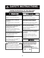
Safety Instructions for the Operator
WARNING
Do not open the equipment.
There are no user-serviceable parts
inside.
Do not disassemble or modify the
equipment.
Fire, electrical shock or serious injury
can result.
Immediately turn off the power at the
switchboard if the equipment is
emitting smoke or fire.
Continued use of the equipment can
cause fire or electrical shock. Contact a
FURUNO agent for service.
Do not maneuver the vessel based
on the depth indication alone.
Grounding may result.
Use the proper fuse.
Fuse rating is shown on the equipment.
Use of a wrong fuse can result in
damage to the equipment.
Do no turn on the equipment with the
transducer out of water.
The transducer may be damaged.
The picture is not refreshed when
picture advancement is stopped.
Maneuvering the vessel in this condition
may result in a dangerous situation.
Use the proper gain setting.
Incorrect gain may produce wrong depth
indication, possibly resulting in a
dangerous situation.
The data presented by this equipment
is intended as a source of navigation
information.
The prudent navigator never relies
exclusively on any one source of navi-
gation information, for safety of vessel
and crew.
CAUTION
WARNING
To avoid electrical shock, do not
remove cover. No user-serviceable
parts inside.
Name:
Warning Label (1)
Type: 86-003-1011-1
Code No.: 100-236-231
A warning label is attached to the
equipment. Do not remove the label.
If the label is missing or damaged,
contact a FURUNO agent or dealer
about replacement.
NOTICE
The TFT LCD is constructed using the
latest LCD techniques, and displays
99.99% of its pixels. The remaining 0.01%
of the pixels may drop out or blink, however
this is not an indication of malfunction.
About the TFT LCD

SAFETY INSTRUCTIONS
iii
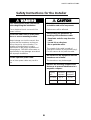
Safety Instructions for the Installer
WARNING
Turn off the power at the switchboard
before beginning the installation.
Fire or electrical shock can result if the
power is left on.
Be sure no water leaks in at the trans-
ducer or sensor mounting location.
Water leakage can sink the vessel. Also
confirm that the transducer and sensor
will not loosen by ship's vibration. The
installer of the equipment is solely
responsible for the proper installation of
the equipment. FURUNO will assume no
responsibility for any damage associated
with improper installation.
Use the specified power cable.
Use of other power cable may result in
fire.
CAUTION
Do not install the equipment where
air bubbles and noise are present.
Performance will be affected.
The following are guidelines for
handling of the transducer cable.
- Keep fuels and oils away from the
cable.
- Locate it in a safe place.
- Do no paint the cable.
The sheath of the cable is made of
chloroprene rubber (or polychloride vinyl).
For this reason do not paint the cable.
Observe the following compass safe
distances to prevent interference to a
magnetic compass:
FCV-620
Standard Steering
compass compass
0.3 m 0.3 m
Do not turn on the equipment with the
transducer out of water.
The transducer may be damaged.
FCV-585
0.5 m 0.3 m
Display
unit

iv
TABLE OF CONTENTS
FOREWORD...............................v
SYSTEM CONFIGURATION.....vi
EQUIPMENT LISTS..................vii
1.OPERATION ...........................1
1.1 Control Description.........................1
1.2 Power On/Off .................................2
1.3 Adjusting Display Contrast and
Brilliance.........................................2
1.4 Choosing a Display Mode..............2
1.5 Choosing Range ............................5
1.6 Adjusting Gain................................5
1.7 Measuring Depth............................6
1.8 Menu Operating Procedure............ 6
1.9 Shifting Range................................7
1.10Choosing Picture Advance Speed
.......................................................8
1.11Suppressing Interference............... 8
1.12Suppressing Low Level Noise........9
1.13Erasing Weak Echoes....................9
1.14A-Scope Display...........................10
1.15Fish Information ...........................11
1.16Alarms..........................................12
1.17FUNC Key.................................... 13
1.18Waypoints ....................................13
1.19Setting Up Nav Data Displays......15
1.20Menu Items ..................................17
2.SYSTEM MENU ....................20
2.1 Displaying System Sub Menu......20
2.2 Range Menu.................................20
2.3 Key Menu.....................................20
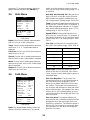
2.4 Lang Menu...................................20
2.5 Units Menu...................................21
2.6 Calib Menu...................................21
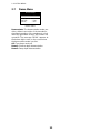
2.7 Demo Menu..................................22
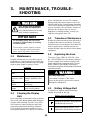
3. MAINTENANCE, TROUBLE-
SHOOTING...........................23
3.1 Maintenance.................................23
3.2 Cleaning the Display Unit.............23
3.3 Transducer Maintenance .............23
3.4 Replacing the Fuse......................23
3.5 Battery Voltage Alert....................23
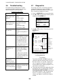
3.6 Troubleshooting ...........................24
3.7 Diagnostics................................... 24
3.8 Test Pattern..................................25
3.9 Memory Clear...............................25
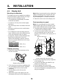
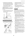
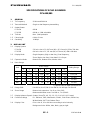
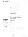
4.INSTALLATION ....................26
4.1 Display Unit.................................. 26
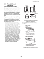
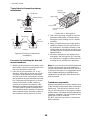
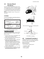
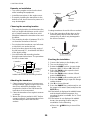
4.2 Thru-hull Mount Transducer......... 27
4.3 Transom Mount Transducer......... 29
4.4 Inside-hull Transducer ................. 29
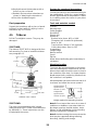
4.5 Triducer........................................ 31
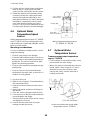
4.6 Optional Water Temperature/Speed
Sensor.......................................... 34
4.7 Optional Water Temperature
Sensor.......................................... 34
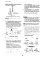
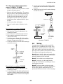
4.8 Wiring........................................... 35
4.9 IEC 61162-1 Data Sentences...... 37
4.10Adjustments after Installation....... 38
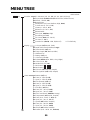
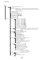
MENU TREE .............................39
SPECIFICATIONS ................SP-1
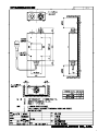
OUTLINE DRAWINGS............D-1
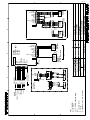
INTERCONNECTION
DIAGRAM ............................... S-1
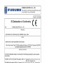
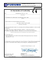
Declaration of Conformity

v
FOREWORD
A Word to FCV-620/585
Owners
Congratulations on your choice of the
FURUNO FCV-620/585 Color LCD Sounder.
We are confident you will see why the
FURUNO name has become synonymous
with quality and reliability.
For over 60 years FURUNO Electric Com-
pany has enjoyed an enviable reputation for
innovative and dependable marine elec-
tronics equipment. This dedication to excel-
lence is furthered by our extensive global
network of agents and dealers.
This equipment is designed and constructed
to meet the rigorous demands of the marine
environment. However, no machine can per-
form its intended function unless operated
and maintained properly. Please carefully
read and follow the recommended proce-
dures for operation and maintenance.
We would appreciate hearing from you, the
end user, about whether we are achieving our
purposes.
Thank you for considering and purchasing
FURUNO equipment.
Features
The FURUNO FCV-620/585 is a dual
frequency (50 kHz and 200 kHz) Color LCD
Sounder. Comprised of a display unit and a
transducer, the FCV-620 displays underwater
conditions on a 5.6-inch color LCD and the
FCV-585 on an 8.4-inch color LCD.
The main features of the FCV-620/585 are
• Bright color LCD gives excellent readability
even in broad daylight.
• Waterproof construction permits installa-
tion on open bridge.
• Automatic function being available on
detecting fish school and bottom at both
shallow and deep depth permits best dis-
play.
• User-programmable nav data displays pro-
vide analog and digital nav data.
• Alarms: Bottom, Fish (bottom lock and
normal), Speed, Water Temperature and
Arrival. (Speed, arrival and water tempera-
ture alarms require appropriate sensor.)
• White line feature helps discriminate fish
lying near the bottom.
• Destination waypoint feature provides
range, bearing, and time-to-go to destina-
tion waypoint (up to 20 waypoints).

vi
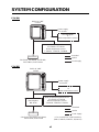
SYSTEM CONFIGURATION
FCV-620
FCV-585
DISPLAY UNIT
CV-620
: Standard
: Option
Power supply
12-24 VDC
: Local Supp
ly
Water temperature/speed sensor
ST-02MSB, ST-02PSB
Water temperature sensor
T-02MSB, T-02MTB, T-03MSB
GPS Navigator
or
Water temperature sensor
Transducer
5
20-5PSD, 520-5MSD, 525-5PWD,
525ST-MSD, 525ST-PWD
: Standard
: Option
Power supply
12-24 VDC
: Local Supply
Water temperature/speed sensor
ST-02MSB, ST-02PSB
Water temperature sensor
T-02MSB, T-02MTB, T-03MSB
GPS Navigator
or
Water temperature sensor
Transducer
520-5PSD, 520-5MSD, 525-5PWD,
525ST-MSD, 525ST-PWD
Matching Box
MB-1100*
*: For connection to 1 kW transducer
(50B-6, 50B-6B, 200B-5S, 50/200-1T)
DISPLAY UNIT
CV-585

vii
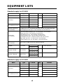
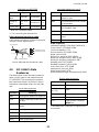
EQUIPMENT LISTS
Standard supply for FCV-620
Standard supply for FCV-585
Name Type Code No. Qty Remarks
Display Unit CV-620 - 1 With hard cover
Transducer
520-5PSD 000-015-204
1
Thru-hull mount
520-5MSD 000-015-212 Thru-hull mount
525-5PWD 000-146-966 Transom mount
Triducer (transducer
plus spd/temp sensor)
525ST-MSD 000-015-263 Thru-hull mount
525ST-PWD 000-015-261 Transom mount
Installation Materials
(CP02-07900)
• Cable assy. (1 pc., KON-004-02M, 000-156-405, for power and data)
• Self-tapping screw (4 pcs., 5x25 SUS304, 000-162-610-10)
Accessories
(FP02-05501)
• Flush mounting sponge (1 pc., 02-154-1601-0, 100-329-460)
• Wing nut (4 pcs., M4 SUS304, 000-863-331)
• Flat washer (4 pcs., M4 SUS304, 000-864-126)
• Spring washer (4 pcs., M4 SUS304, 000-864-256)
• Threaded rod (4 pcs., M4x50 SUS304, 000-162-679-10)
• MJ cable cap (1 pc., 02-154-1221-1, 100-329-441)
• Filter cleaner (1 pc., 02-155-1082-1, 100-332-651-10)
Spare Parts
(SP02-05001)
Fuse (2 pcs., FGBO-A 125V 2A, 000-155-849-10)
Template C22-00502
000-156-349-1X
1 For flush mounting
000-169-612-1X
Operator’s Guide MLG-23740
000-156-373-1X
1
000-169-611-1X
Operator’s Manual OME-23740
000-156-346-1X
1
000-169-608-1X
Name Type Code No. Qty Remarks
Display Unit CV-585 - 1 With hard cover
Transducer
520-5PSD 000-015-204
1
Thru-hull mount
520-5MSD 000-015-212 Thru-hull mount
525-5PWD 000-146-966 Transom mount
Triducer (transducer
plus spd/temp sensor)
525ST-MSD 000-015-263 Thru-hull mount
525ST-PWD 000-015-261 Transom mount

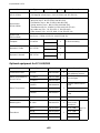
EQUIPMENT LISTS
viii
Optional equipment for FCV-620/585
Name Type Code No. Qty Remarks
Installation Materials
(CP02-07900)
• Cable assy. (1 pc., KON-004-02M, 000-156-405, for power and data)
• Self-tapping screw (4 pcs., 5x25 SUS304, 000-162-610-10)
Accessories
(FP02-05601)
• Flush mounting sponge (1 pc., 02-155-1081-1, 100-330-851-10)
• Wing nut (4 pcs., M4 SUS304, 000-863-331)
• Flat washer (4 pcs., M4 SUS304, 000-864-126)
• Spring washer (4 pcs., M4 SUS304, 000-864-256)
• Threaded rod (4 pcs., M4x50 SUS304, 000-162-679-10)
• MJ cable cap (1 pc., 02-154-1221-1, 100-329-441)
• Filter cleaner (1 pc., 02-155-1082-1, 100-332-651-10)
Spare Parts
(SP02-05001)
Fuse (2 pcs., FGBO-A 125V 2A, 000-155-849-10)
Template C22-00504
000-158-577-1X
1 For flush mounting
000-169-613-1X
Operator’s Guide MLG-23740
000-156-373-1X
1
000-169-611-1X
Operator’s Manual OME-23740
000-156-346-1X
1
000-169-608-1X
Name Type Code No. Qty Remarks
Conversion Cable 02S4147 000-141-082 1
For water temperature
and spd/temp sensors
Water Temperature &
Speed Sensor
ST-02MSB 000-137-986
1 Thru-hull type
ST-02PSB 000-137-987
Water Temperature
T-02MTB 000-040-026
1
Transom mount, w/8 m
cable
T-02MSB 000-040-040 Thru-hull mount
T-03MSB 000-040-027
Thru-hull mount, w/8 m
cable
Inner Hull Kit S 22S0191 000-802-598 1
Matching Box MB-1100 000-041-353 1
For connec-
tion to 1 kW
transducer
For FCV-
585
Transducer
50B-6 000-015-042
1
10 m, 1 kW
50B-6B 000-015-043 15 m, 1 kW
200B-5S 000-015-029 10 m, 1 kW
50/200-1T 000-015-170 10 m, 1 kW

1
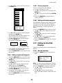
1. OPERATION
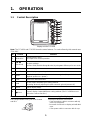
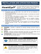
1.1 Control Description
Display unit for FCV-620
Note: The FCV-620 and FCV-585 share the same features. For sake of brevity, this manual uses
“FCV-620”.
How to remove the hard cover
Place fingers below cover, pull cover forward
and lift it.
When removing the display unit
To keep out dust from connectors:
- Cover transducer cable’s connector with MJ
cable cap (supplied).
- Cover two connectors on display unit with their
caps.
- Cover power cable’s connector with its cap.
No. Control Function
1 MENU/ESC
• Opens/closes menu.
• Escapes from current operation.
2
STWX
(TrackPad)
• Moves cursor on the menu.
• Adjusts settings.
• Moves VRM (Variable Range Marker) by using S or T except for nav mode.
3 ENTER Saves settings.
4 RANGE Opens display range setting window.
5MARK
Records the position of an important echo as waypoint. (Outputs latitude and
longitude position to a plotter.)
6 FUNC Opens user defined window.
7GAIN
• Push: Opens automatic gain setting window.
• Rotating: Manually adjusts gain (with automatic gain adjustment off).
8 MODE Selects display mode.
9
/BRILL
• Turns power on/off.
• Opens display contrast/brilliance setting window. (The FCV-585 does not
have the contrast function.)
G
A
I
N
10
0
2
8
4
6
FCV
-
620
M
E
N
U
/
E
S
C
E
N
T
E
R
RANGE
MARK
FUNC
M
O
D
E
B
R
I
L
L
AUTO
N
A
V
1
Z
O
O
M
L
F
D
U
A
L
H
F
Z
O
O
M
N
A
V
2
1
9
2
3
4
5
6
7
8

1. OPERATION
2
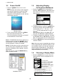
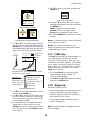
1.2 Power On/Off
1. Press the /BRILL key to turn on the
power.
The unit beeps, the startup screen appears,
and then the equipment checks the ROM
and RAM for proper operation. After the
completion of the equipment check, the last-
used display appears.
Startup screen
2. To turn off the power, press the /BRILL
key more than three seconds.
The time remaining until power is turned off
is counted down on the screen.
Note1: If "ROM/RAM check error!" appears, try
to press any key except the /BRILL key to
start operation. However, the equipment may
not work properly. Contact your dealer.
Note2: The first time you turn on the power (or
any time the power is applied after a memory
reset), the installation menu appears. See the
figure below.
When this occurs, press the MENU/ESC key
twice to close the menu.
Installation menu
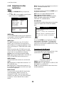
1.3 Adjusting Display
Contrast and Brilliance
1. Press the /BRILL key momentarily to
show the contrast/brilliance adjustment win-
dow. (The FCV-585 does not have the con-
trast function.)
Contrast/brilliance adjustment window
2. To adjust brilliance, press the /BRILL key.
Continual pressing changes the brilliance
continuously (0
→1→...→9→8→...→0→
1→...). “0” is the dimmest and “9” is the
brightest.
After selecting “Brill” by using
S or T, you
may also use W or X to adjust brilliance.
3. To adjust contrast, after selecting “Contrast"
by using
S or T, use W or X (only for FCV-
620). “0” is the lowest and “9” is the highest.
4. Press the ENTER key to save the setting and
close the window.
Note: When the power is reapplied after turning
off the equipment with minimum brilliance, min-
imum brilliance will be set after the equipment
goes through its initial start up. (The start up
screen appears with the maximum brilliance.)
Adjust the brilliance as necessary.
1.4 Choosing a Display Mode
1. Rotate the MODE knob to open the mode
setting window, which is displayed for five
seconds.
W Min Max X
Contrast/Brill
Contrast 5
Brill 9
S/T : Select
[ENTER] : Set
[MENU] : Cancel
NAV1
LF-ZOOM
LF-DEEP
DUAL
HF-SHALLOW
HF-ZOOM
NAV2
MODE
Low frequency zoom mode*
Low frequency mode (50 k)
High frequency mode (200 k)
High frequency zoom mode**
Nav data mode 1
Nav data mode 2
Dual frequency mode
*: The indication at the top on the screen is
B/L-LF, B/Z-LF or M/Z-LF.
**: The indication at the top on the screen is
B/L-HF, B/Z-HF or M/Z-HF.
B/L: Bottom lock, LF: Low frequency,
B/Z: Bottom zoom, HF: High frequency,
M/Z: Marker zoom

1. OPERATION
3
2. Rotate the MODE knob again to choose the
display mode desired.
The screen you chose appears soon there-
after.
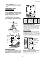
Single frequency display
Low frequency (50 kHz)
The sounder uses ultrasonic signals to detect
bottom conditions. The lower the frequency of
the signal, the wider the detection area. There-
fore, the 50 kHz frequency is useful for general
detection and judging bottom condition.
High frequency (200 kHz)
The higher the frequency of the ultrasonic
signal, the better the resolution. For this reason
the 200 kHz frequency is ideal for detailed
observation of fish schools.
Frequency and coverage area
Single frequency display
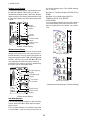
Dual frequency display
The 50 kHz picture appears on the left; the 200
kHz picture on the right. This display is useful for
comparing the same picture with two different
frequencies.
Dual frequency display
Zoom display (50/200 kHz)
Zoom mode expands chosen area of the single
frequency picture. Three modes are available:
bottom lock, bottom zoom and marker zoom.
The default mode is bottom lock. To change a
mode, see page 17.
Bottom lock display
The bottom lock display provides a normal pic-
ture on the right half of the screen and a 10-30
feet (default: 15 feet) wide layer in contact with
the bottom is expanded onto the left half of the
screen. This mode is useful for detecting bottom
fish.
Bottom lock display
Note1: To adjust the range of the zoom display,
go to the Range menu (see page 20).
Note2: To turn on or off the Zoom Marker, go to
the Display menu (see page 18).
50 kHz
200 kH
z
Depth
Display mode
Picture advance speed
Range scale
Gain
49.6
1/1
m
20
40
60
80
0
50k
W
Bottom
Fish school
Color
bar
Alarm icon
G:AF R:A
0.0
15.5 kt
82.6
Data
box
Transmission line
Range
Minute
marker
(Each bar
equals
30 sec.)
Frequency
Beam
width
Resolu-
tion
Detectable
range
Bottom
tail
50 kHz Wide Low Deep Long
200 kHz Narrow High Shallow Short
50 kHz 200 kHz
picture picture
4
7.2
50/200 1/1
0
20
40
60
80
20
40
60
80
G
:AF R:A
W
m
0.0
0
Bottom lock
display
Zoom mark
er
Zoomed
fish
This section
is zoomed.
2
1.7
0
Single
frequency
display
Fish
school
0
40
Bottom
displayed fla
t
10
20
30
0
1
2
3
4
5
1/1
W
G:AF R:A
m
B/L-LF

1. OPERATION
4
Bottom zoom display
This mode expands bottom and bottom fish on
the left-half window. This mode is useful for
determining bottom contour. When the bottom
depth increases, the display automatically shifts
to keep the bottom echo at the lower part of the
screen.
Bottom zoom display
Marker zoom display
This mode expands chosen area of the normal
picture to full vertical size of the screen on the
left-half window. You may specify the portion to
expand by operating the VRM (Variable Range
Marker), which you can shift with
S or T. The
area between the VRM and zoom marker is
expanded. This mode is useful for determining
the size of fish in the middle water.
Marker zoom display
Nav data displays
The nav data displays appear on the left of the
screen. Data other than depth requires appro-
priate sensor.
Two nav data displays are available, Nav Data
1 or Nav Data 2, and you may choose which to
use on the Display menu. The default settings
are as follows.
Nav Data 1: Two-data display (SPEED (STW),
WIND)
Nav Data 2: Four-data display (DEPTH,
TEMPERATURE, TRIP METER,
ODOMETER)
You can display between two and four items in
a nav data display and choose the item and
order to display them. For details, see section
1.19.
Sample Nav Data displays (Default setting)
0
Bottom zoom
display
29.8
Bottom
0
40
10
20
30
32
31
30
29
28
27
Switched with
depth
Single
frequency
display
Zoom
marker
1/1
W
G:AF R:A
m
B/Z-LF
Zoomed
fish
school
Single frequenc
y
display
Variable range
marker
This section
is zoomed
Zoom marker
Marker zoom
display
17.0
2
5.0
0
Fish
school
0
40
10
20
30
21
20
19
18
17
22
1/1
W
G:AF R:A
m
M/Z-LF
1/1
20
40
60
80
0
W
Nav Data 1 display
1/1
20
40
60
80
0
W
Nav Data 2 display

1. OPERATION
5
1.5 Choosing Range
The basic range may be chosen in Auto or
Manual mode.
1. Press the RANGE key to open the range set-
ting window.
Range setting window
2. Use W or X to choose Auto or Manual.
Auto: The range changes automatically to
display the bottom echo on the screen. The
range shifting functions are inoperative in
Auto mode. “R:A” is shown at the top left
corner on the screen.
Manual: The range may be chosen from the
eight ranges. “R:M” is shown at the top left
corner on the screen.
If you choose Auto go to step 4. For manual
go to the next step.
3. For Manual, use
S or T to choose the
range.
*: Japanese unit of depth measurement
Note: Basic ranges may be preset as desired.
For further details, see page 20.
4. Press the ENTER key.
Note: The range mode indication, which
appears at the top-left corner, may be turned on
or off with Header Info on the Display menu. For
details, see page 19.
1.6 Adjusting Gain
The gain may be adjusted automatically
(Fishing or Cruising) or manually.
Fishing and Cruising
The gain (or receiver sensitivity) is adjusted
automatically for Fishing and Cruising mode so
that the bottom is displayed as reddish brown.
Gain offset lets you override automatic gain
adjustment.
1. Press the GAIN knob to open the Auto Gain
setting window.
Auto Gain setting window
2. Press the GAIN knob again to choose
Fishing or Cruising.
You may also use
S or T to choose the
mode.
Fishing: This mode clearly displays weaker
echoes and is for searching fish schools.
“G:AF” is shown at the top left corner on the
screen.
Cruising: This mode clearly displays
stronger echoes (for example, bottom), sup-
presses weak echoes and is for general
cruising.
“G:AC” is shown at the top left corner on the
screen.
Off: For manual adjustment
Adjusting gain offset proceed, if not go to
step 4.
3. If you need, adjust the gain offset with
W or
X (setting range: -5 to +5).
Pressing W lowers the gain, X raises the
gain.
4. Press the ENTER key.
Default ranges
Unit
Basic Range
1234567 8
m 5 10 20 40 80 150 200 300
ft 15 30 60 120 200 400 600 1000
fa 3 5 10 20 40 80 100 150
pb 3 5 10 20 50 100 150 200
HR* 4 8 15 30 50 100 150 200
Range
S
/
T
: Select
[ENTER] : Set
[MENU] : Cancel
15 ft
30 ft
60 ft
120 ft
200 ft
400 ft
600 ft
1000 ft
W Auto Manual X
These are
available wit
h
Manual mod
e.
Auto Gain
S
/
T
: Select
[ENTER] : Set
[MENU] : Cancel
W Min Max X
Offset 0
Fishing
Cruising
Off

1. OPERATION
6
Manual gain adjustment
The GAIN knob adjusts the sensitivity of the
receiver. Generally, use a higher gain setting for
greater depths and a lower setting for shallower
waters.
Examples of proper and improper gain
1. Press the GAIN knob to open the Auto Gain
setting window.
2. Press the GAIN knob again to choose Off.
“G:M” appears at the top left corner on the
screen.
3. Press the ENTER key.
4. Rotate the GAIN knob to adjust the gain. The
setting range is 0.0 to 10.
Adjust so that a slight amount of noise
remains on the screen.
The setting gain is shown at the top of the
screen as G (Gain) + XX (setting value).
1.7 Measuring Depth
The VRM (Variable Range Marker) functions to
measure the depth to fish schools, etc.
1. Use
S or T to place the VRM on the object
to measure depth.
2. Read the VRM depth just above the VRM.
How to measure depth with the VRM
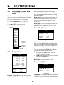
1.8 Menu Operating
Procedure
The FCV-620/585 have five menus: Sounder,
Display, Alarm, Data, and System. Below is the
basic menu operating procedure.
1. Press the MENU/ESC key to open the menu.
Menu
2. Use S or T to choose the menu or sub
menu desired.
The cursor (yellow) shows current selection.
The items in the right window change with
menu selected.
3. Press the ENTER key.
The cursor (yellow) shifts to the menu item
window (right) and the current selection on
Use the proper gain setting.
Incorrect gain may produce wrong depth
indication, possibly resulting in a
dangerous situation.
CAUTION
Gain too high
Gain proper
Gain too low
49.6
1/1
m
20
40
60
80
0
50k
W
G:AF R:A
VRM
Depth to VRM
37.9
Sounder
S
/
T
/
W
/
X
: Select
[ENTER] : Enter
[MENU] : Back
Pic. Advance : 1/1
Zoom Mode
: Bottom Lock
Shift
: 0ft
Bottom Zone
Interference
: Auto
Color Erase : 0%
Clutter
: 0%
White Line : 0%
White Marker
TVG
: Medium
Smoothing
: On
TX Power : Auto
TX Rate
: 10
Transducer*
: 600W
Sounder
Display
Alarm
Data
System
Menu
T
Currently selected menu
Cursor
(yellow)
Menu window
Menu item
window
*: FCV-585
only

1. OPERATION
7
the menu window (left) is displayed to gray.
You may also use X to move the cursor.
4. Use
S or T to choose the menu item
desired and press the ENTER key.
The selected setting box or window appears.
Setting box Setting window
5. Use S or T to choose an option.
6. Press the ENTER key to save the setting.
The setting box or window disappears. To
escape without changing setting press the
MENU/ESC key instead of the ENTER key.
7. To choose another menu press the MENU/
ESC key.
The cursor (yellow) moves to the menu
window. You may also use
W to move the
cursor.
8. Press the MENU/ESC key to close the
menu.
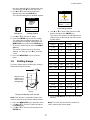
1.9 Shifting Range
The basic range may be shifted up or down in
the Manual mode as follows:
Range and display shift concept
Note: This function is inoperative when Auto
mode is selected on the range setting window.
1. Press the MENU/ESC key to open the menu.
2. Use
S or T to choose Sounder and press
the ENTER key.
3. Use
S or T to choose Shift and press the
ENTER key.
Shift setting window
4. Use S or T to choose the amount of shift
desired and press the ENTER key.
The step for the amount of shift depends on
setting range on the Range sub menu of the
System menu.
5. Press the MENU/ESC key twice to close the
window.
Note: The echo may be lost if the amount of
shift is greater than actual depth.
Off
On
Depth Size
[ENTER] : Set
[MENU] : Cancel
Small
Medium
Large
Display
W
indow can be
s
hifted up and
d
own to select
s
tarting depth.
Unit: ft Unit: m
Range Step Range Step
7 - 10 2 2 - 5 1
11 - 20 5 6 - 10 2
21 - 50 10 11 - 20 5
60 - 100 20 21 - 50 10
110 - 250 50 60 - 100 20
260 - 500 100 110 - 250 50
550 - 1000 200 260 - 500 100
1100 - 2500 500 550 - 800 200
Unit: fa Unit: pb
Range Step Range Step
2 - 5 1 2 - 5 1
6 - 10 2 6 - 10 2
11 - 20511 - 205
21 -50 10 21 - 50 10
60 - 100 20 60 - 100 20
110 - 250 50 110 - 250 50
260 - 400 100 260 - 450 100
Shift
[ENTER] : Set
[MENU] : Cancel

1. OPERATION
8
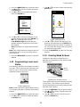
1.10 Choosing Picture
Advance Speed
The picture advance speed determines how
quickly the vertical scan lines run across the
screen. When choosing a picture advance
speed, keep in mind that a fast advance speed
will expand the size of the fish school horizon-
tally on the screen and a slow advance speed
will contract it. A fast advance speed is useful
for observing the rugged bottom minutely. A
slow advance speed is useful for observing the
smooth bottom.
Picture and picture advance speed
1. Press the MENU/ESC key to open the menu.
2. Use
S or T to choose Sounder and press
the ENTER key.
Sounder menu
3. Use S or T to choose Pic. Advance and
press the ENTER key.
Pic. Advance setting window
4. Use S or T to choose picture advance
speed desired and press the ENTER key.
1/16 is the slowest speed and 4/1 is the
fastest speed. 1/16 means one scan line is
produced every 16 transmissions. Current
picture advance is displayed at the top-right
corner of the screen.
5. Press the MENU/ESC key twice to close the
window.
1.11 Suppressing
Interference
Interference from other acoustic equipment
operating nearby or other electronic equipment
on your boat may show itself on the display as
shown in the figure below. Follow the procedure
below to suppress interference.
Interference
Fast
Slow
Sounder
S
/
T
/
W
/
X
: Select
[ENTER] : Enter
[MENU] : Back
Pic. Advance
: 1/1
Zoom Mode
: Bottom Lock
Shift
: 0ft
Bottom Zone
Interference
: Auto
Color Erase : 0%
Clutter
: 0%
White Line : 0%
White Marker
TVG
: Medium
Smoothing
: On
TX Power
: Auto
TX Rate
: 10
Transducer*
: 600W
*: FCV-585
only
Pic. Advance
S
/
T
: Select
[ENTER] : Set
[MENU] : Cancel
4/1
2/1
1/1
1/2
1/4
1/8
1/16
Stop
Slo
w
Fa
st
The picture is not refreshed when
picture advancement is stopped.
Maneuvering the vessel in this condition
may result in a dangerous situation.
CAUTION
Interference from
other sounder
Electrical interferenc
e

1. OPERATION
9
1. Press the MENU/ESC key to open the menu.
2. Use
S or T to choose Sounder and press
the ENTER key.
3. Use
S or T to choose Interference and
press the ENTER key.
Interference setting window
4. Use S or T to choose the degree of sup-
pression desired and press the ENTER key.
Off: Turn off interference rejector.
Low, Medium, High: High provides the
greatest degree of suppression and Low is
the smallest.
Auto: Interference is suppressed automati-
cally.
Note: Turn off the interference rejector when no
interference exists, so as not to miss echoes
from small fish.
5. Press the MENU/ESC key twice to close the
window.
1.12 Suppressing Low Level
Noise
Low intensity "speckles" may appear over most
of screen. This is mainly due to sediment in the
water or noise. These can be suppressed by
adjusting Clutter on the menu.
Clutter appearance
Note: Clutter cannot be adjusted when Fishing
or Cruising is selected on the Auto Gain setting
window.
1. Press the MENU/ESC key to open the menu.
2. Use S or T to choose Sounder and press
the ENTER key.
3. Use
S or T to choose Clutter and press the
ENTER key.
Clutter setting window
4. Use S or T to choose the degree of sup-
pression desired and press the ENTER key.
The setting range is 0 to 100 % in intervals of
ten. The larger the setting value, the greater
the degree of suppression.
5. Press the MENU/ESC key twice to close the
window.
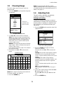
1.13 Erasing Weak Echoes
Sediment in the water or reflections from
plankton may be painted on the display in low
intensity tones.
Appearance of weak echoes
These weak echoes may be erased by using the
“Color Erase”. This function erases weaker
echoes sequentially to show only strong echoes
and clear up the picture.
1. Press the MENU/ESC key to open the menu.
2. Use
S or T to choose Sounder and press
the ENTER key.
3. Use
S or T to choose Color Erase and
press the ENTER key.
Off
Low
Medium
High
Auto
Interference
S
/
T
: Select
[ENTER] : Set
[MENU] : Cancel
Clutter
[ENTER] : Set
[MENU] : Cancel
Weak
echoe
s

1. OPERATION
10
Color Erase setting window
4. Use S or T to choose the color to erase and
press the ENTER key. The setting range is 0
to 50 % in intervals of five. The larger the set-
ting value, the greater the degree of erasion.
5. Press the MENU/ESC key twice to close the
window.
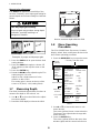
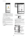
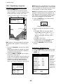
1.14 A-Scope Display
This display shows echoes at each transmission
with amplitudes and tone proportional to their
intensities, on the right of the screen. It is useful
for estimating the kind of fish school and bottom
composition.
Note: In the dual frequency display, the A-
Scope display is only available with the high fre-
quency display.
1. Press the MENU/ESC key to open the menu.
2. Use
S or T to choose Display and press the
ENTER key.
Display menu
3. Use S or T to choose A-Scope and press
the ENTER key.
A-Scope setting box
4. Use S or T to choose the A-Scope presen-
tation type desired and press the ENTER
key.
Normal: Display shows echoes at each
transmission with amplitudes and tone pro-
portional to their intensities.
Peak: “Normal” A-Scope display plus peak-
hold amplitude picture for last five seconds in
dots.
5. Press the MENU/ESC key twice to close the
window.
A-Scope display
Note: To turn off the A-Scope display, choose
Off at step 4 and then press the ENTER key.
Color Erase
[ENTER] : Set
[MENU] : Cancel
Display
S
/
T
/
W
/
X
: Select
[ENTER] : Enter
[MENU] : Back
A-Scope
: Off
Depth Size
: Small
Zoom Marker : Off
Temp Graph
: Off
Window Size
Battery : Off
Color Bar
: On
Palette
: White
Colors : 64
Header Info
: On
Nav Data1
:
Nav Data2
:
Fish Info
: Off
Fish Symbols : Off
Sounder
Display
Alarm
Data
System
Menu
T
Off
Normal
Peak
1/1
50k
W
G:AF R:A
20
40
60
80
0
5
9.8
m
0.0
Single
frequency
display
A-Scope displa
y
Weak echo
(small fish
school or
noise)
School fish
Strong echo
(bottom)
Past amplitude
pictures are
displayed with
dots with Peak
mode.

1. OPERATION
11
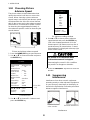
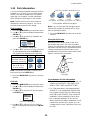
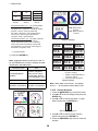
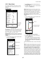
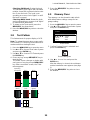
1.15 Fish Information
You can turn the fish symbol indication (Solid or
Striped) on or off. Also, you can show or hide
the fish size and the depth value. For details
about the Fish Symbols, see the information
which follows the procedures in this section.
Note: The fish size found by this sounder is
intended for reference purposes; it is not an
accurate measurement of fish length.
Fish Symbols
1. Press the MENU/ESC key to open the menu.
2. Use
S or T to choose Display and press the
ENTER key.
3. Use
S or T to choose Fish Symbols and
press the ENTER key.
Fish Symbols setting box
4. Use S or T to choose Off, Solid or Striped
as appropriate and press the ENTER key.
The symbol size depends on the fish size.
Note: To hide the fish symbol, choose Off at
step 4 and press the ENTER key.
5. Press the MENU/ESC key twice to close the
window.
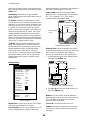
Fish Info
1. Press the MENU/ESC key to open the menu.
2. Use
S or T to choose Display and press the
ENTER key.
3. Use
S or T to choose Fish Info and press
the ENTER key.
Fish Info setting box
4. Use S or T to choose Off, Fish Size or
Depth as appropriate and press the ENTER
key.
Fish symbols with fish info figure
Note: You can show the fish info figure alone
(without fish symbol) by turning off Fish Sym-
bols on the Display menu.
5. Press the MENU/ESC key twice to close the
window.
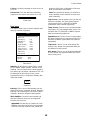
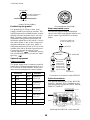
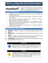
Principle of fish size
Returning echoes at the center of the trans-
ducer beam are used in fish size calculation.
Fish for size calculation are taken from the 200
kHz beam and their size is calculated from their
strengh found with the 50 kHz beam. In the
example below, only the fish at the center of the
figure is used for size calculation.
Principle
Consideration for fish information
• The 600 W transducers which offer size cal-
culation are 520-5PSD, 520-5MSD, 525-
5PWD, 525ST-MSD and 525ST-PWD.
• For 1 kW transducer, the integrated type
50/200-1T is recommended to display the
fish symbol and the fish size. When using
both 50B-6 and 200B-5S, they should be
installed in close proximity to each other.
• Echo intensity depends on fish specie.
When the fish size differs between the indi-
cated value and the fish caught, you can
compensate it on the Calib menu (see sec-
tion 2.6).
Fish size Solid Striped
Large fish symbol
(more than 50 cm, or
more than 20 inches)
Small fish symbol
(10 to 49 cm, or
4 to 19 inches)
Off
Solid
Striped
Off
Fish Size
Depth
15
60
60
15
Solid
(Small
fish symbol)
Solid
(Large
fish symbol)
Striped
(Small
fish symbol)
Striped
(Large
fish symbol)
Fish size or depth is displayed in red.
50 kHz
200 kHz
Page is loading ...
Page is loading ...
Page is loading ...
Page is loading ...
Page is loading ...
Page is loading ...
Page is loading ...
Page is loading ...
Page is loading ...
Page is loading ...
Page is loading ...
Page is loading ...
Page is loading ...
Page is loading ...
Page is loading ...
Page is loading ...
Page is loading ...
Page is loading ...
Page is loading ...
Page is loading ...
Page is loading ...
Page is loading ...
Page is loading ...
Page is loading ...
Page is loading ...
Page is loading ...
Page is loading ...
Page is loading ...
Page is loading ...
Page is loading ...
Page is loading ...
Page is loading ...
Page is loading ...
Page is loading ...
Page is loading ...
Page is loading ...
Page is loading ...
-
 1
1
-
 2
2
-
 3
3
-
 4
4
-
 5
5
-
 6
6
-
 7
7
-
 8
8
-
 9
9
-
 10
10
-
 11
11
-
 12
12
-
 13
13
-
 14
14
-
 15
15
-
 16
16
-
 17
17
-
 18
18
-
 19
19
-
 20
20
-
 21
21
-
 22
22
-
 23
23
-
 24
24
-
 25
25
-
 26
26
-
 27
27
-
 28
28
-
 29
29
-
 30
30
-
 31
31
-
 32
32
-
 33
33
-
 34
34
-
 35
35
-
 36
36
-
 37
37
-
 38
38
-
 39
39
-
 40
40
-
 41
41
-
 42
42
-
 43
43
-
 44
44
-
 45
45
-
 46
46
-
 47
47
-
 48
48
-
 49
49
-
 50
50
-
 51
51
-
 52
52
-
 53
53
-
 54
54
-
 55
55
-
 56
56
-
 57
57


Ask a question and I''ll find the answer in the document
Finding information in a document is now easier with AI
Related papers
Other documents
-
ESAB Pressure Transducer Replacement Troubleshooting instruction
-
 Mark Levinson 585 Quick start guide
-
Uniden QT206 User manual
-
 Hawkeye DT2B-TM User manual
-
Airmar P66 Owners And Installation Manual
-
 Apelco XVA-70 User manual
-
Airmar TRIDUCER P39 Owner's Manual & Installation Instructions
-
 NorCross HawkEye D11S Operating instructions
-
PRESIDENT LTD 260 User manual
-
 Onwa KF-667 User manual


