Invacare Ranger II 250 Series User manual
- Type
- User manual

Ranger II Storm Series
®
Wheelchairs
MWD/FWD
Ranger II
BASIC
Ranger II
STANDARD
Ranger II
JR
Ranger II
250 SERIES
Service Manual
DEALER: THIS MANUAL MUST BE GIVEN TO THE USER
OF THE WHEELCHAIR.
USER: BEFORE USING THIS WHEELCHAIR, READ THIS
MANUAL AND SAVE FOR FUTURE REFERENCE.

2
WARNING/SPECIAL NOTES
W
A
R
N
I
N
G
SAVE THESE INSTRUCTIONS
WARNING
THE PROCEDURES IN THIS MANUAL SHOULD ONLY BE PERFORMED
BY A QUALIFIED TECHNICIAN.
DO NOT SERVICE OR OPERATE THIS EQUIPMENT WITHOUT FIRST
READING AND UNDERSTANDING THIS MANUAL AND THE OWNER’S
MANUAL SUPPLIED WITH THE WHEELCHAIR. IF YOU ARE UNABLE TO
UNDERSTAND THE WARNINGS, CAUTIONS, AND INSTRUCTIONS,
CONTACT INVACARE TECHNICAL SUPPORT BEFORE ATTEMPTING TO
SERVICE OR OPERATE THIS EQUIPMENT - OTHERWISE INJURY OR
DAMAGE MAY RESULT.
SPECIAL NOTES
WARNING/CAUTION notices as used in this manual apply to hazards or unsafe practices
which could result in personal injury or property damage.
NOTICE
THE INFORMATION CONTAINED IN THIS DOCUMENT IS SUBJECT TO CHANGE WITHOUT NO-
TICE.
WHEELCHAIR USER
As a manufacturer of wheelchairs, Invacare endeavors to supply a wide variety of
wheelchairs to meet many needs of the end user. However, final selection of the type of
wheelchair to be used by an individual rests solely with the user and his/her healthcare
professional capable of making such a selection.
WHEELCHAIR TIE-DOWN RESTRAINTS AND SEAT POSITIONING STRAPS
Invacare recommends that wheelchair users NOT be transported in vehicles of any kind
while in wheelchairs. As of this date, the Department of Transportation has not approved
any tie-down systems for transportation of a user while in a wheelchair, in a moving
vehicle of any type.
It is Invacare’s position that users of wheelchairs should be transferred into appropriate
seating in vehicles for transportation and use be made of the restraints made available
by the auto industry. Invacare cannot and does not recommend any wheelchair trans-
portation systems.
AS REGARDS RESTRAINTS - SEAT POSITIONING STRAPS - IT IS THE OBLIGATION OF THE DME
DEALER, THERAPISTS AND OTHER HEALTHCARE PROFESSIONALS TO DETERMINE IF A SEATING
POSITIONING STRAP IS REQUIRED TO ENSURE THE SAFE OPERATION OF THIS EQUIPMENT BY
THE USER. SERIOUS INJURY MAY OCCUR IN THE EVENT OF A FALL FROM A WHEELCHAIR.
S
P
E
C
I
A
L
N
O
T
E
S

3
TABLE OF CONTENTS
T
A
B
L
E
O
F
C
O
N
T
E
N
T
S
TABLE OF CONTENTS
SPECIAL NOTES................................................ 2
SPECIFICATIONS ............................................... 4
PROCEDURE 1 - GENERAL GUIDELINES .......... 7
REPAIR OR SERVICE INFORMATION ................. 7
OPERATING INFORMATION ............................... 7
WARNING/CAUTION LABEL LOCATION ............ 8
PROCEDURE 2- TROUBLESHOOTING ........... 12
FIELD LOAD TEST .......................................... 12
USING HYDROMETER TO CHECK BATTERY
CELLS (LEAD ACID) ..................................... 12
MOTOR TESTING ........................................... 13
MOTOR BRUSH INSPECTION ......................... 14
ELECTRO-MECHANICAL PARKING BRAKE
TESTING ..................................................... 14
PROCEDURE 3 - FRONT RIGGINGS ................ 15
ADJUSTING FLIP-UP REMOVABLE
FOOTBOARD ............................................. 16
ADJUSTING THE REMOVABLE FOOTBOARD ... 16
PROCEDURE 4 - ARMS .................................... 18
REPLACING ARMREST PADS .......................... 18
REPLACING ARMREST PLATE ........................ 18
PROCEDURE 5 - SEAT/BACK ........................... 19
REPLACING SEAT POSITIONING STRAP .......... 19
REPLACING BACK UPHOLSTERY ................... 19
REPLACING CAPTAIN'S SEAT .......................... 20
PROCEDURE 6 - SEAT FRAME ......................... 21
ADJUSTING SEAT DEPTH ................................ 21
ADJUSTING BACK HEIGHT .............................. 21
CHANGING BACK ANGLE ................................ 22
REPLACING BACK CANES .............................. 22
PROCEDURE 7 - ELECTRONICS ..................... 24
REPOSITIONING MKIV JOYSTICK ..................... 24
REMOVING/INSTALLING MKIV CONTROLLER ... 24
PROCEDURE 8 - LIMIT SWITCH ...................... 27
DISCONNECTING/CONNECTING LIMIT
SWITCH ..................................................... 27
ADJUSTING LIMIT SWITCH ............................... 27
PROCEDURE 9 - WHEELS ............................... 29
REPLACING PNEUMATIC TIRES/TUBES -
DRIVE WHEELS/CASTERS ......................... 29
REMOVING/INSTALLING DRIVE WHEELS ......... 29
REMOVING/INSTALLING DRIVE WHEEL HUB .. 30
REPLACING CASTERS ................................... 32
REPLACING FORKS ....................................... 32
The procedures in this manual refer to the following models:
RANGER II MWD models: RANGER II BASIC
RANGER II STANDARD
RANGER II 250
SERIES
.
RANGER II FWD models: RANGER II
BASIC
RANGER II
STANDARD
RANGER II
250 Series
and RANGER II with
Weight Shift Basic Tilt.
PROCEDURE 10 - SHROUDS ........................... 33
REMOVING/INSTALLING SHROUDS .................. 33
PROCEDURE 11 - CROSSBRACES ................ 37
ADJUSTING SEAT WIDTH - INTEGRATED
SLING SEATS ............................................. 37
REPLACING CROSSBRACES - CAPTAIN’S
SEATS........................................................ 39
PROCEDURE 12 - BATTERIES ....................... 41
INSTALLING/REMOVING BATTERIES INTO/
FROM BATTERY BOXES ............................ 41
PROCEDURE 13 - FWD WHEELCHAIRS .......... 46
ASSEMBLING RANGER II FWD ....................... 46
WHEN TO CHARGE BATTERIES ...................... 48
CHARGING BATTERIES ................................... 48
REPLACING BATTERIES ................................. 49
INSTALLING/REMOVING BATTERY BOXES ....... 50
BATTERY TRAY .............................................. 51
REPLACING WIRING HARNESS ..................... 55
REPOSITIONING MOTORS .............................. 59
REPLACING CLUTCH HANDLES - R2
BASIC
................. 60
REPLACING MOTOR/GEARBOX - R2
BASIC
................ 61
REPLACING MOTOR/GEARBOX -R2
STANDARD
...... 62
PROCEDURE 14 - MWD WHEELCHAIRS ......... 64
ASSEMBLING RANGER II MWD ....................... 64
WHEN TO CHARGE BATTERIES ...................... 66
CHARGING BATTERIES ................................... 66
REPLACING BATTERIES ................................. 67
INSTALLING/REMOVING BATTERY BOXES ....... 68
BATTERY TRAY .............................................. 69
REPLACING WIRING HARNESS ..................... 71
STABILIZER IDENTIFICATION .......................... 73
ADJUSTING SPRINGS .................................... 73
ADJUSTING STABILIZERS FOR USER
PREFERENCE ........................................... 74
REPLACING STABILIZER CYLINDERS .............. 75
REPLACING STABILIZER WHEELS ................... 76
REPLACING STABILIZER CYLINDER SPRINGS .. 77
REPOSITIONING MOTORS .............................. 78
REPLACING CLUTCH HANDLES
-R2
BASIC
/R2
250 series
..................................................................... 78
REPLACING MOTOR/GEARBOX -R2
BASIC
................. 79
REPLACING MOTOR/GEARBOX -R2
STANDARD
........ 80
LIMITED WARRANTY ....................................... 83

4
SPECIFICATIONS
S
P
E
C
I
F
I
C
A
T
I
O
N
S
SPECIFICATIONS
PERFORMANCE R2
BASIC
R2
250 series
R2
STANDARD
Speed (M.P.H.): 0 to 3.8 0 to 3.6 0 to 5.8
Turning Radius: > 23-inches > 23-inches > 23-inches
Range (variable)
4
: 18-22 miles 12-14 miles 18-22 miles
L Weight Limitation
5
: 250 lbs. 250 lbs. 300 lbs.
L
NOTE: Refer to PERCENTAGE OF WEIGHT DISTRIBUTION in PROCEDURE 1 of this manual.
NOTE: All specifications are
approximate.
RANGER II MWD - R2
BASIC
R2
STANDARD
R2
250 SERIES
Seat Width Range:
Seat Depth Range:
Back Height Range
Std.:
Opt. Headrest:
Opt. Backrest Ext.:
Back Angle Range:
Seat-to-Floor:
Overall Width (No joystick):
Overall Height:
Weight
3,6
W/O Batteries:
W/Batteries (Gel Cell):
Shipping:
Armrests:
Upholstery:
INTEGRATED SLING SEAT
16, 18 or 20-inches
16, 17 or 18-in. - in 1-inch increments
(17 and 18-in. by extension)
16, 17, 18, 19 or 20-in. - In 1-in increments
N/A
N/A
90
o
to 105
o
- in 5
o
increments
18-1/4-inches
24-7/8-inches
34-3/8-in. - 18-in. Back Height
R2
BASIC
/ R2
250 series
R2
STANDARD
110 to 114 lbs. 112 to 116 lbs.
178 to 182 lbs. 190 to 194 lbs.
134 to 153 lbs. 146 to 155 lbs.
Removable, Flip Back, Fixed or Adjustable
Height - Desk and Full Length
Black Nylon
CAPTAIN'S SEAT
BACK TYPE
LOW LOW SOLID SEAT HIGH
1
(LOB) (LOBSS) (HIB)
19-in. 19-in. 19-in.
17-in. 17-in. 17-in.
16-in. 18-in. 22-in.
N/A N/A 28-in.
23-in. N/A N/A
(55
o
- 114
o
)
2
(98
o
)
2
(35
o
- 170
o
)
2
22-in. 19-1/2-in. 22-in.
24-3/4-in. 24-3/4-in. 24-3/4-in.
35-in. 35-in. 39-in.
R2
BASIC
/ R2
250 series
R2
STANDARD
131 to 135 lbs. 138 to 142 lbs.
206 to 210 lbs. 213 to 217 lbs.
161 to 165 lbs. 168 to 172 lbs.
Flip Back - Adjustable Height - Full Length (Std.)
Vinyl or Cloth with Vinyl (R2
250 SERIES
- Gray fabric
trimmed w/ gray Vinyl)
INTEGRATED SLING SEAT AND CAPTAIN'S SEAT
43-1/2-inches 35-1/2-inches
(With 8-in. rear casters (With 8-in. rear casters
and 93 front riggings) and no front riggings)
7-inch Urethane
12-1/2 x 2-1/4-in. (Std.); 14-in.x 3-in. (Opt.) (Flat Free or Pneumatic)
8 x 1-3/4-in. Semi Pneumatic (Std.), 8 x 2-in. Pneumatic (Opt.)
6 x 2-in. Semi Pneumatic (Opt.)
Swingaway, Removable Adjustable Flip Up Removable Footboard
R2
BASIC
/R2
STANDARD
- 22NF Gel Cell (Two (2) Required); R2
250-SERIES
uses
- U1 GEL CELL)
Overall Length (Drive wheel in Front
Position -
Refer to PERCENTAGE OF
WEIGHT DISTRIBUTION in PROCEDURE
1 of this manual.)
Front Stabilizers
Drive Wheels/Tires:
Casters w/Precision Sealed Bearings:
Footrest/Legrest:
Battery/Size (Not Supplied):
Footnotes:
1. High Back not available on model R2
250 SERIES
.
2. Low and High Back Types have an Infinite adjustment.
Low Backs with Solid Seat have no adjustment.
3. 18-in. wide x 16-in. deep wheelchair with MKIV RII
electronics.
4. Range will vary with battery conditions, surface, ter-
rain and operators weight.
5. Includes seating systems and accessories.
6. Weight varies between motors. R2
BASIC
AND
R2
250 SERIES
have clutches. The R2
STANDARD
has
motor locks.

5
S
P
E
C
I
F
I
C
A
T
I
O
N
S
SPECIFICATIONS
PERFORMANCE R2
BASIC
R2
250 SERIES
R2
STANDARD
Speed (M.P.H.): 0 to 3.8 0 to 3.6 0 to 4.0
Turning Radius: > 25.8-inches > 25.8-inches > 25.8-inches
Range (variable)
3
: 17-22 miles 12-14 miles 12-16 miles
L Weight Limitation
4
: 250 lbs. 250 lbs. 300 lbs.
L
NOTE: Refer to PERCENTAGE OF WEIGHT DISTRIBUTION in PROCEDURE 1 of this manual.
SPECIFICATIONS
NOTE: All specifications are
approximate.
RANGER II FWD -R2
BASIC
R2
STANDARD
R2
250 SERIES
Seat Width Range:
Seat Depth Range:
Back Height Range Std.:
Opt. Headrest:
Opt. Backrest Ext.:
Back Angle Range:
Seat-to-Floor:
Overall Width (No joystick):
Overall Height:
Weight
2,5
W/O Batteries:
W/Batteries (Gel Cell):
Shipping:
Armrests:
Upholstery:
INTEGRATED SLING SEAT
16, 18 or 20-inches
16, 17 or 18-in. - In 1-in. increments
(17 and 18-in. by extension)
16, 17, 18, 19 or 20-in. - In 1-in. increments
N/A
N/A
90
o
to 105
o
- in 5
o
increments
18-1/2-in.
24-5/8-in.
34-3/8-in. - 16-in. Back Height
R2
BASIC
/ R2
250 series
R2
STANDARD
90 to 100 lbs. 105 to 115 lbs.
170 to 180 lbs. 185 to 195 lbs.
105 to 115 lbs. 120 to 130 lbs.
Removable, Flip Back, Fixed or Adjustable
Height - Desk and Full Length
Black Nylon
CAPTAIN'S SEAT
BACK TYPE
LOW LOW SOLID SEAT HIGH
(LOB) (LOBSS) (HIB)
19-in. 19-in. 19-in.
17-in. 17-in. 17-in.
16-in. 18-in. 22-in.
N/A N/A 28-in.
23-in. N/A N/A
(55
o
- 114
o
)
1
(98
o
)
1
(35
o
- 170
o
)
1
22-in. 19-1/2-in. 22-in.
24-3/4-in. 24-3/4-in. 24-3/4-in.
35-in. 35-in. 39-in.
R2
BASIC
/ R2
250 series
R2
STANDARD
122 to 127 lbs. 138 to 142 lbs.
203 to 207 lbs. 218 to 222 lbs.
153 to 157 lbs. 168 to 172 lbs.
Flip Back - Adjustable Height - Full Length (Std.)
Vinyl or Cloth with Vinyl (R2
250 SERIES
- Gray fabric
trimmed w/ gray Vinyl)
INTEGRATED SLING SEAT AND CAPTAIN'S SEAT
LDRIVE WHEEL POSITION
REAR POSITION MIDDLE POSITION FORWARD POSITION
47-1/4-inches 48-1/4-inches 49-1/4-inches
40-1/2-inches 40-1/2-inches N/A
L
NOTE: Refer to PERCENTAGE OF WEIGHT DISTRIBUTION in PROCEDURE 1 of
this manual.
12-1/2 x 2-1/4-in. (Std.); 14-in.x 3-in. (Opt.) (Flat Free or Pneumatic)
8 x 1-3/4-in. Semi Pneumatic (Std.), 8 x 2-in. Pneumatic (Opt.)
6 x 2-in. Semi Pneumatic (Opt.)
Swingaway, Removable Adjustable Flip Up Removable Footboard
22NF Gel Cell (Two (2) Required); R2
250-SERIES
uses
- U1 GEL CELL)
Overall Length
With 8-in. rear casters and
93 front riggings:
With 8-in. rear casters
and no front riggings:
Drive Wheels/Tires:
Casters w/Precision Sealed Bearings:
Footrest/Legrest:
Battery/Size (Not Supplied):
Footnotes:
1. Low and High Back Types have an Infinite adjustment.
Low Backs with Solid Seat have no adjustment.
2. 18-in. wide x 16-in. deep wheelchair with MKIV RII elec-
tronics.
3. Range will vary with battery conditions, surface, ter-
rain and operators weight.
4. Includes seating systems and accessories.
5. Weight varies between motors. R2
BASIC
AND
R2
250 SERIES
have clutches. The R2
STANDARD
has
motor locks.

6
SPECIFICATIONS
NOTE: All specifications
are approximate.
RANGER II FWD - R2
JR
INTEGRATED SLING SEAT
Seat Width Range: 14-inches
Seat Depth Range: 16 to 18-inches - In 1-inch increments (17 and 18-inch by extension)
Back Height Range: 16 to 20-inches - In 1-inch increments
Back Angle Range: 90
o
to 105
o
- in 5
o
increments
Seat-to-Floor: 18-1/2-inches
Overall Width
(No joystick): 20-5/8-inches
Overall Height: 34-3/8-inches - 16-inch Back Height
Overall Length L REAR DRIVE POSITION
With 8-inch rear casters
and 93 front riggings: 43-1/2-inches
With 8-inch rear casters
and no front riggings: 32-1/2-inches
L
NOTE: Refer to PERCENTAGE OF WEIGHT DISTRIBUTION in
PROCEDURE 1 of this manual.
Drive Wheels/Tires 12-1/2 X 2-1/4-inch (Pneumatic-Standard, Flat Free - Optional)
Caster w/Precision
Sealed Bearings: 8 x 1-3/4-inch Semi Pneumatic (Std.), 8 x 2-inch Pneumatic (Opt.)
6 x 2-inch Semi Pneumatic (Opt.)
Footrests/Legrests: Swingaway, Removable
Weight
1
W/O Batteries: 83 lbs.
W/Batteries (Gel Cell): 153 lbs.
Shipping: 98 lbs.
Armrests: Removable, Flip Back, Fixed or Adjustable Height - Desk and Full Length
Upholstery: Black Nylon
Batteries: U1 Gel Cell
PERFORMANCE
Speed (M.P.H.): 0 to 3.6
Turning Radius: 24-inches
Range (variable)
2
: 14 miles
L Weight Limitation
3
: 200 lbs.
L
NOTE: Refer to PERCENTAGE OF WEIGHT DISTRIBUTION in PROCEDURE 1 of this manual.
Footnotes:
1. 14-in. wide x 16-in. deep wheelchair with MKIV RII electronics.
2. Range will vary with battery conditions, surface, terrain and operators weight.
3. Includes seating systems and accessories.
SPECIFICATIONS
S
P
E
C
I
F
I
C
A
T
I
O
N
S

7
GENERAL GUIDELINES PROCEDURE 1
G
E
N
E
R
A
L
G
U
I
D
E
L
I
N
E
S
WARNING
CONTROLLER SETTINGS FOR R2
JR
Set-up of the Electronic Control Unit is to be performed ONLY by qualified technicians.
Factory setting of the controller MUST be used for daily activities. Reprogramming the
controller to reflect aggressive settings (i.e. increased acceleration, turning, braking etc..)
could cause the wheelchair to tip over resulting in serious injury to the user and/or dam-
age to the surrounding property.
REPAIR OR SERVICE INFORMATION
Set-up of the Electronic Control Unit is to be performed ONLY by qualified technicians. The
final tuning adjustments of the controller may affect other activities of the wheelchair.
Damage to the equipment could occur under these circumstances. If any individual other
than a qualified technician performs any work on these units, the warranty is void.
OPERATING INFORMATION
GENERAL WARNINGS
Performance adjustments should only be made by professionals of the healthcare field or
persons fully conversant with this process and the driver's capabilities. Incorrect settings
could cause injury to the driver, bystanders, damage to the chair and to surrounding
property.
After the wheelchair has been set-up, check to make sure that the wheelchair performs to
the specifications entered during the set-up procedure. If the wheelchair does NOT per-
form to specifications, turn the wheelchair OFF immediately and reenter set-up specifica-
tions. Repeat this procedure until the wheelchair performs to specifications.
DO NOT use parts, accessories, or adapters other than those authorized by Invacare.
TIRE PRESSURE - DO NOT use your wheelchair unless it has the proper tire pressure (P.S.I.). DO
NOT overinflate the tires. Failure to follow these suggestions may cause the tire to explode
and cause bodily harm. The recommended tire pressure is listed on the side wall of the tire.
BATTERIES - The warranty and performance specifications contained in this manual are
based on the use of deep cycle gel cell or sealed lead acid batteries. Invacare strongly
recommends their use as the power source for this unti.
The use of rubber gloves and safety glasses is recommended when working with batteries.
Carefully read battery/battery charger information prior to installing, servicing or operat-
ing your wheelchair.
ELECTRICAL
Grounding Instructions:
DO NOT, under any circumstances, cut or remove the round grounding prong from any
plug used with or for Invacare products. Some devices are equipped with three-prong
(grounding) plugs for protection against possible shock hazards. Where a two-prong wall
receptacle is encountered, it is the personal responsibility and obligation of the customer
to contact a qualified electrician and have the two-prong receptacle replaced with a
properly grounded three-prong wall receptacle in accordance with the National Electri-
cal Code. If you must use an extension cord, use ONLY a three-wire extension cord having
the same or higher electrical rating as the device being connected. In addition, Invacare
has placed RED/ORANGE WARNING TAGS on some equipment. DO NOT remove these
tags. Carefully read battery/battery charger information prior to installing, servicing or
operating your wheelchair.
This Procedure Includes the Following:
Repair or Service Information Operating Information

8
GENERAL GUIDELINESPROCEDURE 1
G
E
N
E
R
A
L
G
U
I
D
E
L
I
N
E
S
WARNING/CAUTION LABEL LOCATION - MWD MODELS
(R2
BASIC
/R2
STANDARD
/R2
250 SERIES
)
CAUTION
HIGH BACK CAPTAIN'S
SEATS ONLY - Disconnect
limit switch BEFORE re-
moving seat - damage to
seat can occur.
Push Bracket
Crossbrace
Wiring
Harness for
Battery Box
Lid
Stabilizers may vary depending
on manufacturing date of the
wheelchair
NOTE: This warning label is found on mod-
els built before 3/1/00. For warning label
locations on chairs built after 3/1/00, refer
to the warning label on page 11.

9
Push Bracket
Crossbrace
WARNING/CAUTION LABEL LOCATION - FWD MODELS
(R2
BASIC
/R2
STANDARD
/R2
250 SERIES
)
WARNING
Replacement con-
troller MUST be
SAME part number.
Motor
Assembly
Controller
(Back View)
CAUTION
HIGH BACK CAPTAIN'S SEATS
ONLY - Disconnect limit switch
BEFORE removing seat - dam-
age to seat can occur.
NOTE: Caution Label is
located on side shroud.
Side Frame
GENERAL GUIDELINES PROCEDURE 1
G
E
N
E
R
A
L
G
U
I
D
E
L
I
N
E
S
CAUTION
Repositioning the motors WILL af-
fect the stability and/or perfor-
mance of the wheelchair. Refer to
PERCENTAGE OF WEIGHT DISTRIBU-
TION in the Owner's Manual BEFORE
repositioning motors. 1080267
Wiring Harness for
Battery Box Lid
NOTE: This warning label is found on models built before 3/1/
00. For warning label locations on chairs built after 3/1/00, refer
to the warning label on page 11.

10
WARNING/CAUTION LABEL LOCATION - FWD MODELS (R2
JR
)
WARNING
Replacement con-
troller MUST be
SAME part number.
Motor
Assembly
Controller
(Back View)
CAUTION
Repositioning the motors WILL af-
fect the stability and/or perfor-
mance of the wheelchair. Refer to
PERCENTAGE OF WEIGHT DISTRIBU-
TION in the Owner's Manual BEFORE
repositioning motors. 1080267
Side Frame
WARNING
Pinch Point
Side Frame
Battery
Tray
GENERAL GUIDELINESPROCEDURE 1
G
E
N
E
R
A
L
G
U
I
D
E
L
I
N
E
S
Wiring Harness
for Battery
Box Lid

11
BATTERY WARNING LABEL LOCATION
WARNING
This POSITIVE (+) RED Battery Cable MUST
connect to the POSITIVE (+) Battery
Terminal(s)/Post(s), otherwise serious
damage will occur to the electrical sys-
tem. Refer to the Owner’s Manual. DO
NOT remove this label. 1095558
WARNING
This NEGATIVE (+) BLACK Battery Cable
MUST connect to the NEGATIVE (+) Bat-
tery Terminal(s)/Post(s), otherwise serious
damage will occur to the electrical sys-
tem. Refer to the Owner’s Manual. DO
NOT remove this label. 1095559
WARNING
DO NOT allow battery cable(s) to contact
the opposite battery terminal(s)/post(s). Re-
place cable(s) immediately if cable(s) insu-
lation becomes damaged. Failure to observe
these warnings may result in an electrical
short with serious personal injury resulting.
DO NOT remove this label. 1095561
NOTE: Only U1 battery box top is show for clarity.
Warning Labels are located on the group 22 battery
box top in the same manner.
NOTE: These warning labels are found on models built
after 3/1/00. For warning label locations on chairs built
before 3/1/00, refer to specific drive system for the
wheelchair.
GENERAL GUIDELINES PROCEDURE 1
G
E
N
E
R
A
L
G
U
I
D
E
L
I
N
E
S

12
(+)
(-)
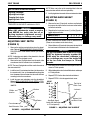
FIGURE 1 - FIELD LOAD TEST
Battery Charger
Connector
Digital Voltmeter
FIELD LOAD TEST (FIGURE 1)
NOTE: The following test can also be performed through
the controller of the wheelchair along with a remote pro-
grammer. Refer to the individual CONTROLLER
MANUAL supplied with each wheelchair.
Old batteries lose their ability to store and release power,
due to increased internal resistance. This means that as
you try to take power from the battery, some of that power
is used up in the process of passing through the battery,
resulting in less voltage at the posts. The more power
drawn, the lower the voltage available. When this lost volt-
age drops the output 1.0 volts under load (2.0 for a pair),
replace the batteries.
Testing under load is the only way to spot this problem.
While special battery load testing equipment is available,
it is costly and difficult to transport.
Use a digital voltmeter to check battery charge level at the
charger connector. It is located on the base of the wheel-
chair frame.
NOTE: READ the instructions CAREFULLY before us-
ing the digital voltmeter.
NOTE: Invacare recommends that ONLY qualified ser-
vice personnel perform this test.
1. Ensure that power is OFF.
2. Make sure battery is fully charged. An extremely dis-
charged battery will exhibit the same symptoms as a
bad one.
3. Place a one (1) piece of wood taller than the axle of
the drive wheels between the wheelchair and a wall,
workbench or other stationary object.
4. Remove the footrests from the wheelchair and place
the stabilizer wheels or the front of the wheelchair
against the piece of wood.
5. Place the voltmeter leads into the charger plug on the
wheelchair. Most digital voltmeters are not affected by
polarity, however, analog meters (meters with swing-
ing needles) can be and should be used carefully. A
good meter reading should be 25.5 to 26 VDC.
6. Have two (2) individuals (one [1] on each arm) apply
as much downward pressure as possible on the arms
of the wheelchair.
USING HYDROMETER TO CHECK
BATTERY CELLS (LEAD ACID)
(FIGURE 2)
NOTE: Perform this procedure when a digital voltmeter is
not available.
WARNING
NEVER smoke or strike a match near the
batteries. If the caps of the battery cells
are removed, NEVER look directly into
them when charging the battery.
The use of rubber gloves and safety glasses
is recommended when testing the battery
cells.
When reading a hydrometer, DO NOT al-
low any liquid to come in contact with
your eyes or skin. It is a form of acid and
can cause serious burns, and in some
cases, blindness. If you do get battery acid
on you, flush the exposed areas with cool
water IMMEDIATELY. If the acid comes into
contact with eyes or causes serious burns,
get medical help IMMEDIATELY.
The battery acid can damage your wheel-
chair, clothing, and household items.
Therefore, take readings cautiously and
only in designated areas.
TROUBLESHOOTINGPROCEDURE 2
This Procedure Includes the Following:
Field Load Test
Using Hydrometer To Check Battery Cells (Lead
Acid)
Motor Testing
Motor Brush Inspection
Electro-Mechanical Parking Brake Testing
7. Turn the wheelchair ON and push the joystick for-
ward, trying to drive the wheelchair through the sta-
tionary object. This puts a heavy load on the batteries
as they try to push through the stationary object. Read
the meter while the motors are straining to determine
the voltage under load.
NOTE: If the voltage drops to less than 23.5 volts from a
pair of fully charged batteries while under load, they should
be replaced regardless of the unloaded voltages.
T
R
O
U
B
L
E
S
H
O
O
T
I
N
G

13
TROUBLESHOOTING PROCEDURE 2
T
R
O
U
B
L
E
S
H
O
O
T
I
N
G
WARNING
ONLY use distilled water when topping off
the battery cells.
Most batteries are not sold with instructions.
However, warnings are frequently noted
on the cell caps. Read them carefully.
1. Remove the battery box(es). Refer to one (1) of the fol-
lowing:
FWD WHEELCHAIRS -
INSTALLING/REMOVING
BATTERY BOXES in PROCEDURE 13 of this
manual.
MWD WHEELCHAIRS -
INSTALLING/REMOVING
BATTERY BOXES in PROCEDURE 14 of this manual.
2. Remove the battery caps from the battery.
3. Squeeze the air from the hydrometer.
4. Place the hydrometer into a battery cell.
NOTE: DO NOT fill hydrometer more than 3/4 full.
5. Draw up sufficient acid to cover float balls.
6. Tap lightly to remove air bubbles.
7. Number of floating balls indicates charge.
Number of Floating Balls
0 Discharged
1 25% Charged
2 50% Charged
3 75% Charged
4 100% Charged
* 5 Overcharged
* Check charging system.
8. Flush the liquid back into the same cell after reading the
float. Repeat this step until all cells have been properly
read. A shorted or dead cell can be detected when it is
the only cell that does not charge.
FIGURE 2 - USING A HYDROMETER TO
CHECK BATTERY CELLS (LEAD ACID)
Number of Floating
Balls Will Vary
According to Charge
9. Flush hydrometer in cold running water by allowing
the water to rise into hydrometer as far as possible.
Do this several times to guard against burn damage.
10. Replace the battery caps.
11. Reinstall battery boxes. Refer to one (1) of the follow-
ing:
FWD WHEELCHAIRS -
INSTALLING/REMOVING
BATTERY BOXES in PROCEDURE 13 of this
manual.
MWD WHEELCHAIRS -
INSTALLING/REMOVING
BATTERY BOXES in PROCEDURE 14 of this manual.
MOTOR TESTING (FIGURE 3)
1. On the 4-pin motor connector, locate the two (2) con-
tacts in the red and black housings.
2. Set the digital multimeter to measure ohms (Ω).
3. Measure the resistance between the two (2) motor
contacts.
NOTE: A normal reading is between 1 and 5 ohms
(
Ω
). A reading of 0 ohms (
Ω
) or in excess of 15 ohms
(
Ω
) indicates a problem. High readings are generally
caused by bad connections and/or damaged brushes.
Contact authorized dealer or Invacare.
FIGURE 3 - MOTOR TESTING
Motor Connector
Ohmmeter

14
ELECTRO-MECHANICAL PARKING
BRAKE TESTING (FIGURE 5)
1. On the four-pin motor connector, locate the side by
side connectors in the black housings.
2. Set the digital multimeter to read ohms (Ω).
3. Measure the resistance between the two (2) brake
contacts. A normal reading is 100 ohms (Ω). A read-
ing of 0 ohms (Ω) or a very high reading; i.e., MEG
ohms or O.L. (out of limit) indicates a shorted brake
or an open connection respectively. If either condition
exists, send the motor to Invacare Technical Service
for inspection/repair.
CAUTION
A shorted electro-mechanical brake will
damage the brake output section in the con-
troller. DO NOT connect a shorted electro-
mechanical brake to a good controller mod-
ule. A shorted brake MUST be replaced.
NOTE: A bad motor can damage the controller module
but a bad controller should NOT damage a motor.
4 Pin Motor Connector
Ohmmeter
Cap
Motor
Cap
4 Pin Motor Connector
Motor
FIGURE 5 - ELECTRO-MECHANICAL
PARKING BRAKE TESTING
MOTOR BRUSH INSPECTION
(FIGURE 4)
There are two (2) contact brushes on the motors located
under the brush caps on the motor housing. If these caps
are hard to remove they are either overtightened or the
motor has become very hot. Let motors cool. If caps still
cannot be removed, it is recommended that the motor be
sent to Invacare Technical Services for inspection/repair.
NOTE: It is very important to note which way the brush
comes out of the motor. The brush MUST be placed into
the motor exactly the same way to ensure good contact
with the commutator.
1. Once the motor brush caps have been removed, pull
the brushes out of the motor. The end of the brushes
should be smooth and shiny and the spring should
not be damaged or discolored. If one or both of the
brushes are damaged, only the damaged or worn
brushes need be replaced. It is very important that
any time a brush is replaced, it must be “burned in”.
This is accomplished by running the motor for one
hour in each direction with a half hour break in-be-
tween. This should also be done with little or no load
on the motor, i.e., put the wheelchair up on blocks so
the drive (large) wheels do not contact the ground
and run the wheelchair. A motor with only one brush
replaced will only carry a small percentage of its rated
load capacity until the NEW brush is burned in.
FIGURE 4 - MOTOR BRUSH INSPECTION
T
R
O
U
B
L
E
S
H
O
O
T
I
N
G
TROUBLESHOOTINGPROCEDURE 2

15
This Procedure Includes the Following:
Adjusting Flip-Up Removable Footboard
Adjusting the Removable Footboard
WARNING
After ANY adjustments, repair or service and
BEFORE use, make sure that all attaching
hardware is tightened securely - otherwise
injury or damage may result.
PROCEDURE 3
F
R
O
N
T
R
I
G
G
I
N
G
S
FRONT RIGGINGS
Flip Up Footboard
HEIGHT - MWD WHEELCHAIRS
Washer
Hex
Screw
Locknut
Footboard
Mounting
Bracket
FIGURE 1 - ADJUSTING FLIP-UP
REMOVABLE FOOTBOARD (ANGLE)
Caplug
Cap
Hex
Screw
Caplug
Washer
Wheelchair Frame
Footboard
Mounting
Bracket
Bushing
Seven (7)
Mounting
Positions
Footboard Pivot
ADJUSTING FLIP-UP REMOVABLE
FOOTBOARD
NOTE:This footboard assembly is located on models built
BEFORE 3/1/00. Refer to
ADJUSTING THE REMOV-
ABLE FOOTBOARD for the footboard assembly on
models built AFTER 3/1/00 in this procedure of the manual.
NOTE: The following procedures are for both FWD and
MWD wheelchairs, unless otherwise noted.
Angle (FIGURE 1)
NOTE: This procedure is for FWD wheelchair only.
NOTE: Angle availability is limited when the motors are in
the forward-most position.
1. Remove the caplug caps.
2. Remove the front hex screw and caplug washer that
secure the footboard mounting bracket and bushing
to the wheelchair.
3. Repeat STEPS 1-2 for the opposite front hex screw
and caplug washer.
4. Move the footboard mounting brackets to one (1) of
three (3) positions.
NOTE: To ensure the existing hex screws tighten securely,
apply Loctite 242
®
onto the threads.
5. Reinstall the two (2) hex screws and caplug washers
through the two (2) footboard mounting brackets and
bushings and into the wheelchair.
Footboard Pivot
FIGURE 2 - ADJUSTING FLIP-UP
REMOVABLE FOOTBOARD (HEIGHT)
Loctite - Registered Trademark of Loctite Corporation.
6. Torque the two (2) hex screws to 156-in/lbs.
7. Reinstall the two (2) caplug caps.
Height (FIGURE 2)
1. If necessary, remove the four (4) caplug caps.
2. Remove the hex screw, two (2) spacers, washers
and locknut that secure one (1) of the footboard pivots
to the footboard mounting bracket.
3. Repeat STEP 2 for opposite side of the wheelchair.
4. Move the footboard pivots to one (1) of the following:
MWD WHEELCHAIRS: one (1) of seven (7) positions.
FWD WHEELCHAIRS: one (1) of five (5) positions.
Flip Up Footboard
HEIGHT - FWD WHEELCHAIRS
Washer
Hex
Screw
Locknut
Footboard Mounting
Bracket
Five (5)
Mounting
Positions
Caplug
Cap

16
Footplate
Clamps
Removable
Footboard
ADJUSTING DEPTH
Mounting
Positions
Flat Head Screws
Barrel Nut
Barrel Nut
DETAIL "A"
Proper
Footplate
Clamp
Position for
MWD
Wheelchairs
Proper
Footplate
Clamp
Position for
FWD
Wheelchairs
ADJUSTING THE REMOVABLE
FOOTBOARD
NOTE:This footboard assembly is available on models
built AFTER 3/1/00. Refer to ADJUSTING THE FLIP-UP
REMOVABLE FOOTBOARD for the footboard assem-
bly on models built BEFORE 3/1/00 in this procedure of
the manual.
NOTE: The following procedures are for both FWD and
MWD fwheelchairs, unless otherwise noted.
Depth (FIGURE 3)
NOTE: There is no footboard depth adjustment for 16-
inch wide MWD wheelchairs.
1. Remove the four (4) flat head screws and barrel nuts
that secure the removable footboard to the two (2)
footplate clamps.
2. Move the removable footboard to one (1) of the four (4)
positions.
NOTE: Before reinstalling the four (4) flat head screws,
make sure the footplate clamps are in the proper position
as shown in DETAIL "A".
3. Reinstall the four (4) flat head screws and barrel nuts
that secure the removable footboard to the two (2)
footplate clamps. Tighten securely.
Angle
ADJUSTING FOOTBOARD ANGLE (FIGURE 3).
1. Loosen, but do not remove, the four (4) flat head screws
and barrel nuts that secure the removable footboard
to the two (2) footplate clamps.
NOTE: Because of the two (2) support tubes, the angle of
the removable footboard can be adjusted downward ONLY.
2. Grasp the front of the removable footboard and rotate
it DOWNWARD until the desired angle is reached.
3. While holding the removable footboard in place, tighten
the four (4) flat head screws and barrel nuts securely.
FIGURE 3 - ADJUSTING FLIP-UP
REMOVABLE FOOTBOARD
Removable
Footboard
Barrel Nut
Flat
Head
Screw
Angle Can Be Adjusted
Downward ONLY
FRONT
Footplate
Clamp
ADJUSTING FOOTBOARD ANGLE
5. Resecure the two (2) footboard pivots to the footboard
mounting brackets with the hex screws, spacers,
washers and locknuts. Refer to FIGURE 2 for the cor-
rect hardware orientation.
6. Torque the two (2) hex screws to 156in/lbs. and back
off the hex screws 1/8-1/4 of a revolution.
7. If necessary, reinstall the four (4) caplug caps.
PROCEDURE 3
F
R
O
N
T
R
I
G
G
I
N
G
S
FRONT RIGGINGS

17
4. Remove the nut, flat washer and that secure the threaded
arm on the height adjustment bracket to the footboard
bracket. Refer to DETAIL “B”.
5. Perform one (1) of the following:
A. MWD WHEELCHAIRS - Move the height adjust-
ment bracket to one (1) of seven (7) height positions.
B. FWD WHEELCHAIRS - Move the height adjustment
bracket to one (1) of five (5) height positions.
6. Reinstall the flat washer and nut that secures the threaded
arm on the height adjustment bracket to the footboard
bracket. Refer to DETAIL “B”.
7. Reinstall mounting screw, caplug washer, flat washer and
nut that secures the two (2) large washers and support
tube to the height adjustment bracket and footboard
bracket. Refer to DETAIL “A”.
8. Reinstall the caplug caps.
9. Repeat STEPS 2-8 for the opposite footboard bracket.
10. Reinstall the removable footboard plate. Refer to
REMOV-
ING/INSTALLING THE REMOVABLE FOOTBOARD
ONTO/FROM THE WHEELCHAIR in PROCEDURE
3 of the Owner’s Manual.
ADJUSTING FOOTBOARD MOUNTING
BRACKET ANGLE - FWD MODELS ONLY
(FIGURE 4).
NOTE: Angle availability is limited when the motors
are in the forward-most position.
1. Remove the caplug cap.
2. Remove the front hex screw and caplug washer that
secure the footboard mounting bracket and bushing
to the wheelchair.
3. Repeat STEPS 1-2 for the opposite footboard mount-
ing bracket.
4. Move the footboard mounting brackets to one (1) of
three (3) positions.
NOTE: To ensure the existing hex screws tighten securely,
apply Loctite 242 onto the threads.
5. Reinstall the two (2) hex screws and caplug washers
through the two (2) footboard mounting brackets and
bushings and into the wheelchair.
6. Torque the two (2) hex screws to 13-ft/lbs.
7. Reinstall the two (2) caplug caps.
Height (FIGURE 5)
1. Remove the removable footboard plate. Refer to
PREPARING REMOVABLE FOOTBOARD FOR
WHEELCHAIR TRANSPORTATION in PROCE-
DURE 3 of the Owner’s Manual.
2. Remove the caplug cap.
3. Remove the mounting screw, caplug washer, flat washer
and nut that secures the two (2) large washers and sup-
port tube to the height adjustment bracket and footboard
bracket. Refer to DETAIL “A”.
FIGURE 4 - ADJUSTING
REMOVABLE FOOTBOARD - ADJUSTING
FOOTBOARD MOUNTING BRACKET ANGLE
FIGURE 5 - ADJUSTING FLIP-UP
REMOVABLE FOOTBOARD - HEIGHT
Bushing
Footboard
Pivot
Assemblies
Front Hex
Screw
Caplug
Cap
Caplug
Washer
Battery
Tray
3 Mounting
Positions
Footboard
Mounting
Bracket
PROCEDURE 3
F
R
O
N
T
R
I
G
G
I
N
G
S
FRONT RIGGINGS
NOTE: MWD footboard bracket shown for clarity. Footboard
bracket on FWD models adjusts in the same manner.
Footboard
Bracket
Nut
Flat Washer
Mounting
Positions
Threaded Arm
Height
Adjustment
Bracket
DETAIL “B”
Caplug
Cap
Mounting
Screw
Caplug
Washer
Flat Washer
Nut
Height Adjustment
Bracket
Footboard
Bracket
Two (2) Large
Washers
Support Tube
DETAIL “A”

18
A
R
M
S
ARMSPROCEDURE 4
REPLACING ARMREST PADS
(FIGURE 1)
1. Remove the mounting screws that secures the front
of the armrest pad to the armrest plate.
2. Remove the mounting screw that secures the rear of
the armrest pad and armrest insert to the armrest
plate.
3. Remove the existing armrest pad and position the
new armrest pad on the armrest plate.
4. Line up the mounting holes in the armrest insert, arm-
rest plate and new armrest pad.
5. Reinstall the rear mounting screw through the arm-
rest insert, armrest plate and armrest pad and tighten
securely.
6. Reinstall the front mounting screw into the armrest
plate and new armrest pad and tighten securely.
Armrest
Insert
Mounting
Screw
Armrest
Pad
Armrest Plate
FIGURE 1 - REPLACING ARMREST PADS
Mounting
Screw
REPLACING ARMREST PLATE
(FIGURE 2)
1. If necessary, remove the three (3) hex bolts, spacers
and locknuts that secure the joystick mounting bracket
to the armrest plate.
2. Remove armrest pad. Refer to
REPLACING ARM-
REST PADS in this procedure of the manual.
3. Remove the lug bolt, washers and locknut that secure
the existing armrest plate to the seat frame assembly.
4. Position the new armrest plate on the seat frame as-
sembly and secure with the lug bolt, washers and lock-
nut. Refer to FIGURE 2 for correct hardware orienta-
tion.
5. Reinstall armrest pad. Refer to
REPLACING ARM-
REST PADS in this procedure of the manual.
6. If necessary, reinstall the three (3) hex bolts, spacers
and locknuts that secure the joystick mounting bracket
to the armrest plate.
7. Repeat STEPS 1-6 for the opposite armrest plate, if
necessary.
FIGURE 2 - REPLACING ARMREST PLATE
FRONTREAR
This Procedure Includes the Following:
Replacing Armrest Pads
Replacing Armrest Plate
NOTE: The following procedures are for Captain's
seats only.
WARNING
After ANY adjustments, repair or service
and BEFORE use, make sure that all at-
taching hardware is tightened securely -
otherwise injury or damage may result.
Joystick Mounting Bracket
Hex Bolts
Spacers
Locknuts
Phillips
Screw
Armrest Insert
Phillips Screw
Armrest Pad
Armrest Plate
Lug Bolt
Washers
Locknuts
Washers
Seat Frame
Assembly

19
PROCEDURE 5SEAT/BACK
S
E
A
T
/
B
A
C
K
Hex Bolts
(Apply Loctite
242 and torque
to 75-inch
pounds)
Locknuts
Back Upholstery
Washer
Phillips
Screw
Tie Wrap Mounting Holes
7. Reinstall the Captain's seat onto the wheelchair. Re-
fer to
REMOVING/INSTALLING CAPTAIN'S SEAT in
PROCEDURE 5 of the owner's manual, part number
1080722.
REPLACING BACK UPHOLSTERY
(FIGURE 2)
NOTE: The following procedure is for Integrated sling
seat wheelchairs only.
1. Flip the armrests up and out of the way. Refer to US-
ING/ADJUSTING FLIP BACK ARMRESTS in PRO-
CEDURE 4 of the owner's manual, part number
1080722.
2. Cut the tie-wraps that secure the bottom of the exist-
ing back upholstery to the wheelchair frame.
3. Remove the two (2) phillips screws and washers that
secure the existing back upholstery to the back canes.
4. Remove the two (2) hex bolts, washers and locknuts
that secure one (1) back cane to the wheelchair frame.
NOTE: It is necessary to remove only one (1) back cane
to replace the back upholstery.
5. Pull the loose back cane out of the existing back
upholstery.
6. Pull the existing back upholstery up and over the
mounted back cane.
7. Install new back upholstery over mounted back cane.
Washers
FIGURE 2 - REPLACING BACK UPHOLSTERY
Back Cane
This Procedure Includes the Following:
Replacing Seat Positioning Strap
Replacing Back Upholstery
Replacing Captain's seat
WARNING
After ANY adjustments, repair or service
and BEFORE use, make sure that all at-
taching hardware is tightened securely -
otherwise injury or damage may result.
REPLACING SEAT POSITIONING
STRAP
Captain's Seats (FIGURE 1)
1. Remove the Captain's seat from the wheelchair. Refer
to
REMOVING/INSTALLING CAPTAIN'S SEAT in PRO-
CEDURE 5 of the owner's manual, part number
1080722.
2. Remove the two (2) hex bolts, washers and locknuts
that secure the seat positioning strap to the seat frame
assembly.
3. Remove the two (2) halves of the seat positioning strap
from the seat frame assembly.
4. Position the two (2) new seat positioning strap halves on
the inside of the seat frame assembly as shown in
FIGURE 1.
5. Position the mounting holes in the two (2) new seat po-
sitioning strap halves with the mounting holes in the seat
frame assembly.
6. Reinstall the two (2) hex bolts, washers and locknuts
that secure the seat positioning strap to the seat frame
assembly and tighten securely.
FIGURE 1 - REPLACING SEAT POSITIONING
STRAP - CAPTAIN'S SEATS
Seat Positioning
Strap
Seat Frame
Assembly
Hex Bolt
Washer
Locknut

20
8. Slide the loose top half of the back cane through the
new back upholstery.
9. Using the mounted back cane as a guide, reinstall the
two (2) hex bolts that secure the top half of the back
cane to the bottom half of the back cane.
NOTE: Make sure the back canes are mounted to the
same height.
WARNING
The top and bottom half of the back canes
MUST be tightened securely together BE-
FORE using the wheelchair, otherwise in-
jury or damage may occur. Use Loctite 242
on the hex bolts and torque to 75-inch
pounds.
10. Use Loctite 242 on the hex bolts and torque into the
back canes to 75-inch pounds.
11. While holding the hex bolt, reinstall the locknut and
torque to 75-inch pounds.
12. Repeat STEP 11 for the other hex bolt and locknut.
13. Securely tighten the new back upholstery to the back
canes with the two (2) phillips screws and washers.
14. Secure the bottom of the new back upholstery to the
wheelchair frame with tie-wraps.
NOTE: Clean upholstery with warm DAMP cloth and mild
detergent to remove superficial soil.
WARNING
Laundering or moisture will reduce flame
retardation of the upholstery.
Washers
FIGURE 3 - REPLACING CAPTAIN'S SEAT
Hex Screws (Apply
Loctite 242)
Seat Frame
Assembly
Captain's Seat
REPLACING CAPTAIN'S SEAT
(FIGURE 3)
1. Remove the Captain's seat from the wheelchair. Refer
to REMOVING/INSTALLING CAPTAIN'S SEAT in PRO-
CEDURE 5 of the owner's manual part number
1080722.
2. Remove the four (4) hex screws and washers that
secure the existing captain's seat to the seat frame
assembly.
3. Line up mounting holes in the new captain's seat with
mounting holes in the seat frame assembly.
4. Apply Loctite 242 to the hex screws.
5. Install the four (4) hex screws and washers through
the seat frame assembly and into the new captain's
seat. Tighten securely.
6. Install the new captain's seat onto the wheelchair. Re-
fer to
REMOVING/INSTALLING CAPTAIN'S SEAT in
PROCEDURE 5 of the owner's manual, part number
1080722.
PROCEDURE 5 SEAT/BACK
S
E
A
T
/
B
A
C
K
Seat Frame
Assembly
Page is loading ...
Page is loading ...
Page is loading ...
Page is loading ...
Page is loading ...
Page is loading ...
Page is loading ...
Page is loading ...
Page is loading ...
Page is loading ...
Page is loading ...
Page is loading ...
Page is loading ...
Page is loading ...
Page is loading ...
Page is loading ...
Page is loading ...
Page is loading ...
Page is loading ...
Page is loading ...
Page is loading ...
Page is loading ...
Page is loading ...
Page is loading ...
Page is loading ...
Page is loading ...
Page is loading ...
Page is loading ...
Page is loading ...
Page is loading ...
Page is loading ...
Page is loading ...
Page is loading ...
Page is loading ...
Page is loading ...
Page is loading ...
Page is loading ...
Page is loading ...
Page is loading ...
Page is loading ...
Page is loading ...
Page is loading ...
Page is loading ...
Page is loading ...
Page is loading ...
Page is loading ...
Page is loading ...
Page is loading ...
Page is loading ...
Page is loading ...
Page is loading ...
Page is loading ...
Page is loading ...
Page is loading ...
Page is loading ...
Page is loading ...
Page is loading ...
Page is loading ...
Page is loading ...
Page is loading ...
Page is loading ...
Page is loading ...
Page is loading ...
Page is loading ...
-
 1
1
-
 2
2
-
 3
3
-
 4
4
-
 5
5
-
 6
6
-
 7
7
-
 8
8
-
 9
9
-
 10
10
-
 11
11
-
 12
12
-
 13
13
-
 14
14
-
 15
15
-
 16
16
-
 17
17
-
 18
18
-
 19
19
-
 20
20
-
 21
21
-
 22
22
-
 23
23
-
 24
24
-
 25
25
-
 26
26
-
 27
27
-
 28
28
-
 29
29
-
 30
30
-
 31
31
-
 32
32
-
 33
33
-
 34
34
-
 35
35
-
 36
36
-
 37
37
-
 38
38
-
 39
39
-
 40
40
-
 41
41
-
 42
42
-
 43
43
-
 44
44
-
 45
45
-
 46
46
-
 47
47
-
 48
48
-
 49
49
-
 50
50
-
 51
51
-
 52
52
-
 53
53
-
 54
54
-
 55
55
-
 56
56
-
 57
57
-
 58
58
-
 59
59
-
 60
60
-
 61
61
-
 62
62
-
 63
63
-
 64
64
-
 65
65
-
 66
66
-
 67
67
-
 68
68
-
 69
69
-
 70
70
-
 71
71
-
 72
72
-
 73
73
-
 74
74
-
 75
75
-
 76
76
-
 77
77
-
 78
78
-
 79
79
-
 80
80
-
 81
81
-
 82
82
-
 83
83
-
 84
84


Invacare Ranger II 250 Series User manual
- Type
- User manual
Ask a question and I''ll find the answer in the document
Finding information in a document is now easier with AI
Related papers
-
Invacare Power 9000 User manual
-
-
-
-
-
-
-
-
-
Other documents
-
Sanyo Projector Accessories POA-MD18DVI User manual
-
Toro Weight Kit, 2005 and Before ProLine Fixed-Deck Mid-Size Mowers Installation guide
-
-
Burley Euro Light User manual
-
Crawford & Burke HCB0150-HD Installation guide
-
 Teraflex 1005200 Installation guide
-
L.A. Steelcraft LA-PN204-RB15 Installation guide
-
-
Kyosho MDW301 MJ Aluminum Upper Cover(FWD) User manual
-
Dorel DASE3605 Owner's manual
