Ericsson Orion is an 800 MHz mobile radio system that offers reliable communication with a range of features for professional users. With its frequency stability of 0.00015% and temperature range of -30°C to +60°C, it ensures consistent performance in various conditions. The device supports up to 192 conventional channels and up to 800 MHz EDACS systems/groups, allowing for versatile communication options.
Ericsson Orion is an 800 MHz mobile radio system that offers reliable communication with a range of features for professional users. With its frequency stability of 0.00015% and temperature range of -30°C to +60°C, it ensures consistent performance in various conditions. The device supports up to 192 conventional channels and up to 800 MHz EDACS systems/groups, allowing for versatile communication options.


-
 1
1
-
 2
2
-
 3
3
-
 4
4
-
 5
5
-
 6
6


Ericsson Orion is an 800 MHz mobile radio system that offers reliable communication with a range of features for professional users. With its frequency stability of 0.00015% and temperature range of -30°C to +60°C, it ensures consistent performance in various conditions. The device supports up to 192 conventional channels and up to 800 MHz EDACS systems/groups, allowing for versatile communication options.
Ask a question and I''ll find the answer in the document
Finding information in a document is now easier with AI
Related papers
-
Ericsson Orion Maintenance Manual
-
-
-
Ericsson ORION LBI-39175A Service section User manual
-
-
-
-
-
-
Other documents
-
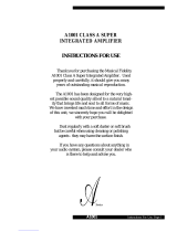 Musical Fidelity A1001 User manual
-
 Musical Fidelity A1001 User manual
-
GE LBI-31564A User manual
-
 Ericsson GE LBI-31932E Maintenance Manual
-
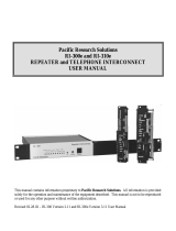 Pacific Digital RI-300e User manual
-
FEIN 31342621201 User guide
-
HAMTRONICS T301 Owner's manual
-
-
Kenwood TK-6900S User manual
-
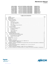 M/A-Com 19D902797G6 Maintenance Manual


