
En-1
English
中國語
1. SAFETY PRECAUTIONS
• Be sure to read this Manual thoroughly before installation.
• The warnings and precautions indicated in this Manual contain important information
pertaining to your safety. Be sure to observe them.
• Hand this Manual, together with the Operating Manual, to the customer. Request the
customer to keep them on hand for future use, such as for relocating or repairing the
unit.
WARNING
Indicates a potentially or imminently hazardous situation
which, if not avoided, could result in death or serious injury.
CAUTION
Indicates a potentially hazardous situation that may result in
minor or moderate injury or damage to property.
WARNING
• Installation of this product must be done by experienced service technicians or
professional installers only in accordance with this manual. Installation by non-profes-
sional or improper installation of the product might cause serious accidents such as
injury, water leakage, electric shock, or re. If the product is installed in disregard of
the instructions in this manual, it will void the manufacturer’s warranty.
• Do not turn on the power until all work has been completed. Turning on the power
before the work is completed can cause serious accidents such as an electric shock
or a re.
• If refrigerant leaks when you are working, ventilate the area. If the leaking refrigerant
is exposed to a direct ame, it may produce a toxic gas.
• Installation must be performed in accordance with regulations, codes, or standards
for electrical wiring and equipment in each country, region, or the installation place.
• This appliance is not intended for use by persons (including children) with reduced
physical, sensory or mental capabilities, or lack of experience and knowledge, unless
they have been given supervision or instruction concerning use of the appliance by a
person responsible for their safety. Children should be supervised to ensure that they
do not play with the appliance.
CAUTION
• Read carefully all of safety information written in this manual before you install or use
the air conditioner.
• Install the unit by following local codes and regulations in force at the place of
installation, and the instructions provided by the manufacturer.
• This unit is part of a set constituting an air conditioner. The unit must not be installed
alone or be installed with non-authorized device by the manufacturer.
• Always use a separate power supply line protected by a circuit breaker operating on
all wires with a distance between contact of 3 mm for this unit.
• To protect the persons, earth (ground) the unit correctly, and use the power cable
combined with a circuit breaker and an Earth Leakage Circuit Breaker (ELCB).
• The units are not explosion proof, and therefore should not be installed in explosive
atmosphere.
• To avoid getting an electric shock, never touch the electrical components soon after
the power supply has been turned off. After turning off the power, always wait 5
minutes or more before you touch the electrical components.
• This unit contains no user-serviceable parts. Always consult experienced service
technicians for repairing.
• When moving or relocating the air conditioner, consult experienced service techni-
cians for disconnection and reinstallation of the unit.
• Do not place any other electrical products or household belongings under indoor unit
or outdoor unit. Condensation dripping from the unit might get them wet, and may
cause damage or malfunction of your property.
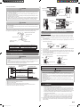
2. ABOUT THIS PRODUCT
2.1.
Precautions for using R410A refrigerant
The basic installation work procedures are the same as conventional refrigerant (R22) models.
However, pay careful attention to the following points:
Since the working pressure is 1.6 times higher than that of conventional refrigerant (R22) mod-
els, some of the piping and installation and service tools are special. (See the following table.)
Especially, when replacing a conventional refrigerant (R22) model with a new refrigerant R410A
model, always replace the conventional piping and flare nuts with the R410A piping and are nuts.
Models that use refrigerant R410A have a different charging port thread diameter to pre-
vent erroneous charging with conventional refrigerant (R22) and for safety. Therefore,
check beforehand. [The charging port thread diameter for R410A is 1/2-20 UNF.]
Be more careful that foreign matter (oil, water, etc.) does not enter the piping. Also,
when storing the piping ,securely seal the opening by pinching, taping, etc.
When charging the refrigerant, take into account the slight change in the composition of the gas and
liquid phases. And always charge from the liquid phase where refrigerant composition is stable.
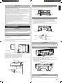
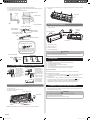
2.2. Special tools for R410A
Tool name Contents of change
Gauge manifold
Pressure is high and cannot be measured with a conven-
tional (R22) gauge. To prevent erroneous mixing of other
refrigerants, the diameter of each port has been changed.
It is recommended the gauge with seals -0.1 to 5.3 MPa (-1
to 53 bar) for high pressure.
-0.1 to 3.8 MPa (-1 to 38 bar) for low pressure.
Charge hose
To increase pressure resistance, the hose material and base
size were changed.
Vacuum pump
A conventional vacuum pump can be used by installing a
vacuum pump adapter.
Gas leakage detector Special gas leakage detector for HFC refrigerant R410A.
Copper pipes
It is necessary to use seamless copper pipes and it is desirable that the amount of residual
oil is less than 40 mg/10 m. Do not use copper pipes having a collapsed, deformed or
discolored portion (especially on the interior surface). Otherwise, the expansion value or
capillary tube may become blocked with contaminants.
As an air conditioner using R410A incurs pressure higher than when using R22, it is neces-
sary to choose adequate materials.
WARNING
Do not use the existing (for R22) piping and are nuts.
If the existing materials are used, the pressure inside the refrigerant cycle will rise and
cause failure, injury, etc. (Use the special R410A materials.)
When installing and relocating the air conditioner, do not mix gases other than
the specied refrigerant (R410A) to enter the refrigerant cycle.
If air or other gas enters the refrigerant cycle, the pressure inside the cycle will rise to
an abnormally high value and cause failure, injury, etc.
AIR CONDITIONER
Wall Mounted Type
INSTALLATION MANUAL
Contents
1. SAFETY PRECAUTIONS .................................................................. 1
2. ABOUT THIS PRODUCT................................................................... 1
3. GENERAL SPECIFICATION ............................................................. 2
4. ELECTRICAL REQUIREMENT ......................................................... 2
5. SELECTING THE MOUNTING POSITION ....................................... 2
6. INSTALLATION WORK ..................................................................... 3
7. ELECTRICAL WIRING ..................................................................... 5
8. FINISHING ........................................................................................ 5
9. FRONT PANEL REMOVAL AND INSTALLATION ............................. 6
10. TEST RUN ......................................................................................... 6
11. REMOTE CONTROLLER INSTALLATION ........................................ 6
12.
REMOTE CONTROLLER CUSTOM CODE SETTING ........................... 7
13. FUNCTION SETTING........................................................................ 7
14. CUSTOMER GUIDANCE .................................................................. 8
15. ERROR CODES ................................................................................ 8
PART No. 9387802009
For authorized service personnel only.
9387802009_IM.indb 1 2017/12/15 15:50:14


 1
1
 2
2
 3
3
 4
4
 5
5
 6
6
 7
7
 8
8


Fujitsu ASTG07JECB Installation guide
Fujitsu ASWX12LECA Installation guide
Fujitsu ASGG07LJCA Installation guide
Fujitsu RSG07LJCA Installation guide

