Crown Heritage BC419601012 Installation guide
- Type
- Installation guide

S TEP- B Y - S TEP
STAIRWAY
CONSTRUCTION
Eighteen easy-to-follow steps for the skilled carpenter
Handy checklist lets you use the Crown Heritage
catalog to choose your components
Background information helps you understand the
stairway construction process
Over sixty detailed illustrations
STEP- BY- STEP
STAIRWAY
CONSTRUCTION
CROWN HERIT
AGE
PO BOX 130, NORTH WILKESBORO, NC 28659
WWW
.CROWNHERITAGE.COM
800.745.5931
© COPYRIGHT 2005 (CH214/03.25.05/80000)
V
isit t
he Cr
o
wn Heritage Design
Library to download CAD stairpart
dr
a
wings f
or y
our plans.
WWW.CROWNHERITAGE.COM

ii
Crown Heritage Stair System components are the highest
quality available anywhere. Turned from solid red oak, the
rich wood grain comes alive with the application of stains
and varnishes. You may also select components turned from
other hardwoods that are suitable for paint finishes. Every
Crown Heritage component has been inspected and
certified to be free from defects.
Crown Heritage stairways are easy to build. Using this
manual and specially designed components exclusive to
Crown Heritage, you can build a stairway unmatched in
strength and beauty. An intermediate knowledge of
carpentry, a knowledge of your local building codes and a
set of quality tools are all you will need.
Finally, Crown Heritage System components are easy to buy.
The convenient displays and generous inventories make the
task of obtaining the parts you need easier than ever before.
If you should find any part temporarily out of stock, just
place an order with a salesperson and your parts will be
shipped through our rapid delivery system to the store for
conv
enient pickup.
INTRODUCTION
i
Many skilled amateur handymen, and even experienced
professional contractors, are reluctant to tackle stairway
construction. And yet, there are few other design elements
that can rival a fine hardwood stairway in adding drama
and value to the interior of a home. The instructions in this
manual have been written in plain language. We invite you
to use your basic carpentry skills to follow the nineteen
steps in the Crown Heritage system. Regardless of whether
your installation is over-the-post or post-to-post, traditional
alignment or rail alignment, in the end, you will have a
sturdy, beautiful stairway. Take a look at the system outline
at the end of the Introduction section and you’ll see how
our step-by-step approach can put real value into a home.
In this introduction, you will learn some basic facts about
Crown Heritage Stair Systems. Before you begin your
stairway, familiarize yourself with the nineteen steps in
Sections A and B.
In the Introduction section you will:
• Learn how the step-by-step system works.
• Disco
ver why Crown Heritage parts are best for you.
• Learn basic facts about stairways and their
construction.
INTRODUCTION
T HE C ROWN H ERITAGE
P ROMISE
StairNotes are some of the many features that make Crown
Her
it
ag
e stairways so easy to build. The steps in Sections A and
B give you specific instructions about things you must do to
install a stair part.
StairNotes explain the reasoning behind the steps, and provide
other helpful information. That’s because Crown Heritage thinks
it is im
por
tant for you to fully understand the stairway
construction process.
W HY
C ROWN H ERITAGE?
W HAT IS A
S TAIRN OTE?
SECTION
C
ONTENTS
:
i
The Cr
own Heritage Promise
ii Why Crown Heritage?
ii
What is a S
t
airNo
te?
iii
Stairway Basics
iv
What
’
s Y
our S
tyle?
v
Com
par
ison T
able
vi
More Important Facts
vii
Cont
ents

iv
The Crown Heritage Stair System includes a wide variety of
hardwood and forged iron parts which allow for the
construction of two basic stairway designs: post-to-post and
over-the-post (see Fig. i-2 and i-3).
In the Crown Heritage catalog, you can familiarize yourself
with the various components in a stair system. You will find
seven wood and eight forged iron collections of balusters
and newels to choose from. Four of these collections are
suitable for either post-to-post or over-the-post installations
(“Williamsburg,” “1800’s,” “Carolina” and “Colonial”).
Hampton and Classic are two very popular collections that
are only available for post-to-post installations.
Crown Heritage also offers the choice between “traditional”
and “rail oriented” baluster systems. Most historic
(traditional) balustrades have bottom features such as
bottom blocks and turnings that align parallel with the
treads, and top features such as rings, top blocks and top of
flutes that align parallel with the handrail. Using the
patented “Crown System” balusters, perfect alignment of
the baluster top features can be achieved, regardless of
whe
t
her t
he ins
tallation has two or three balusters per step.
Other stair part manufacturers cannot offer this alignment.
“Rail oriented” balusters are turned so that all features, both
t
op and bottom, align with the handrail as long as all
balusters are trimmed to length from the bottom.
Bullnose
starting step
Volute fitting on
s
tarting newel
NOTE: Gooseneck fitting on
landing newel
INTRODUCTION
i
ii
A stairway is made up of two basic elements. The first is the
rough stair carriage that consists of a series of stringers that
provide structural support, and basic elements such as treads
and risers for moving people from one level to another. The
second element is the balustrade that contributes safety as
well as beauty. It is topped off with a handrail system that
people may use to support themselves as they go up or
down the stairs. The primary structural supports for the
balustrade are called newels. Safety and secondary support
are provided by balusters (see Fig. i-1).
INTRODUCTION
Intermediate
landing newel,
13" top squre
Starting newel,
5" top square
Post-to-post
half newel
Wall mounted
colonial rail
Over easing,
returned end
Starting newel,
5" top square
Starting/balcony
newel,
5" top square
Oval rosette
Balcony newel,
10" top square
Over-the-post
half newel
Level quarterturn
with cap
Right hand 1 riser
gooseneck, no cap
1 riser gooseneck
with tandem cap
Left hand 1 riser
gooseneck with cap
Pin top
balusters
Mitered return tread
Up easing
Right hand 2 riser
gooseneck with cap
Right hand
turnout
Turnout
newel
Double bullnose
starting step
Volute
newel
Left hand volute
Skirt
bracket
Landing
newel
Over
easing
Starting
newel
Starting
easing
1 riser gooseneck
with tandem cap
Left hand
turnout
Landing
newel
Round rosette
Square top
balusters
Landing
newel
Kneewall
S TAIRWAY
B ASICS
FIG. i-1 - Stairway Terminology
FIG. i-2 - Typical over-the-post stairway
FIG. i-3 - Typical post-to-post stairway
W HAT’ S Y OUR
S TYLE?

vi
The Crown Heritage handrail comes in several styles and is
available either “plowed” to accept square-top balusters or
“unplowed” for pin-top balusters. Refer to the table on
page v for suggestions on matching handrail with your
favorite Crown Heritage collection.
Fittings (see Fig. i-4) are handrail parts used mainly, but not
exclusively, in over-the-post installations. Fittings like the
volute shown at the base of the handrail in Fig. i-2 add an
extra element of drama and beauty to the handrail. Easings
and goosenecks make it possible to fit the handrail to the
geometry of almost any stairway.
Starting steps (see Fig. i-5) are either of the “bullnose” type
(as shown in Fig. i-2), or the “quarter circle” type. Consult
StairNote Five: All About Starting Steps for additional
background information on starting steps.
The Crown Heritage System also features the specialized
hardware needed for building a sturdy stairway. Suggestions
for use of the hardware are found throughout this manual.
Left hand turnout
Starting easing
Left hand volute
Left hand
2 rise gooseneck
INTRODUCTION
v
INTRODUCTION
Bullnose starting step
(double end model)
Quarter circle starting step
(double end model)
FIG. i-4 - Handrail fittings
FIG. i-5 - Starting steps can be either “bullnose” type or “quarter circle” type
C OMPARISON
T ABLE
M ORE I MPORTANT
F ACTS
Suitable for Over-the-Post
x x x x x x
Suitable for Post-to-Post
x x x x x x x
Square top balusters available*
x x x x x x
Pin top balusters available
x x x x x x
W
illiamsbur
g
1800’s
Jef
f
erson
Carolina
Colonial
Hampton
Classic
*Requires plowed rail.
6010
x
6210
x x x x x x
6310
x x x x x
6519
x x x x x
6203
x
6100
x x x x x x x
Williamsburg
1800’s
Jefferson
Carolina
Colonial
Hampton
Classic
Best Handrail Selection:

v
ii
S TAIRN OTES
viii
CONTENTS
SECTION B:
Layout and Construction of the Balustrade
Follow the twelve steps in this section to add the balustrade,
the newels, balusters and handrail to your stairway.
10 . . ST
EP
B.1 Lay Out the Balustrade
10 . . . . . . B.1a Find the Baluster Line and Mark
Baluster Positions
13 . . . . . . B.1b Mark the Newel Positions
14 . . S
TEP B.2 All About Newels
14 . . STEP B.2a Post-to-Post Newels
17 . . STEP B.2b Over-the-Post Newels
20 . . S
TEP B.3 Install the Starting Newel
20 . . . . . . B.3a Installing a Starting Newel in an Over-the-
Post Stairway With a Bullnose Starting Step
23 . . . . . . B.3b Installing a Starting Newel in Over-the-
Post or Post-to-Post Stairways with Plain
Tread or Mitered Tread
25 . . S
TEP B.4 Install the Starting Step
26 . . S
TEP B.5 Install the Remaining Treads
27 . . STEP B.6 Install the Landing Newel(s)
28 . . STEP B.7 Install the Balcony Newel(s)
29 . . S
TEP B.8 Install the Half-Newel or Rosette
30 . . STEP B.9 Assemble and Dry Fit the Handrail
30 . . . . . . B.9a Over-the-Post Handrail
34 . . . . . . B.9b Post-to-Post Handrail
35 . . STEP B.10 Install the Balusters
37 . . . . . . B.10a Installing Pin Top Balusters
38
. . . . . . B.10b Installing Square Top Balusters
39 . . . . . . B.10c Installing Forged Iron
43 . . STEP B.11 Complete the Balustrade Assembly
4
4
. . . . . . B.
1
1a Stairways with Pin Top Balusters
45 . . . . . . B.11b Stairways with Square Top Balusters
46 . . S
TEP B.12 Stains, Varnishes and Paints: Finishing
Your Balustrade
APPENDICES
4
7 . . Bending Rail Installation
50
. .
Troubleshooting Reference
53
. .
Har
dware Installation Instructions
56 . . The Promenade Series
60
. .
4" Spher
e R
ule T
able
CONTENTS
SECTION A:
Layout and Construction of the Rough Stair Carriage
Follow the seven steps in this section if you intend to design
and build a stairway from scratch. If you are constructing a
balustrade on an existing stairway or remodeling, review
Section A, then go directly to Section B.
1. . . S
TEP A.l Cut the Stringers
3. . . STEP A.2 Install the Stringers
4. . . STEP A.3 Brace and Block the Stringers
5. . . STEP A.4 Install Skirt Board
6. . . STEP A.5 Install the Risers
8. . . S
TEP A.6 Dry Fit the Starting Step
9. . . S
TEP A.7 Dry Fit the Stair Treads
S TAIRN OTES
22
. . . . . .
Six: S
t
ar
ting N
e
w
els and Handrail Height
23 . . . . . . Seven: The Williamsburg Collection
24 . . . . . . Eight: How to Notch a Newel
25 . . . . . . Nine: Squeakless Stairways
36 . . . . . .Ten: All About Balusters
43 . . . . . . Eleven: The Classic Collection:
Br
eaking All the Rules
1 . . . . . . . One: Planning for Headroom and Width
2
. . . . . . .
T
wo: How to Calculate “Rise” and “Run”
3
. . . . . . .
Three: How to Make a Pitch Block
5 . . . . . . . Four: Why Use Skirt Boards?
7
. . . . . . .
F
iv
e: All A
bout S
t
arting Steps

2
SECTION A
S TAIRN OTE
H OW TO C ALCULATE
“RISE” AND “RUN”
1
A solid and durable stairway depends on its support system.
In this section, you will learn how to plan and build the
load-bearing structure that will become the means for
moving people and objects from one level of your building
to the next. Consult a qualified professional for load-
bearing requirements.
Accurate and correct construction of the rough stair
carriage will make it much easier for you to install the
balustrade (Section B).
STEP A.1 – Cut The Stringers
See StairNote One: Planning for Headroom and
Stairway Width
See StairNote Two: How to Calculate “Rise” and “Run”
After referring to StairNote Two: How to Calculate “Rise”
and “Run,” use a framing square, lay out the correct
number of risers and treads on a 2 x 12 (see Fig. 1-1).
Remember that in any stairway, the number of treads is
alw
a
y
s one less t
han the number of risers since a stairway
always begins and ends with a riser.
K
eep in mind also that the nosing on the treads will project
about 1" from the riser and must be kept from interfering
with a door or with passage in a hallway.
The first riser must be cut shorter than the others by the
thickness of the tread (1
1
/32"). Note this will automatically
incr
ease the topmost riser by the same amount, but this will
be made up when the treads are installed.
Cut at least one stringer for each 12 to 18 inches of
stairway width.
See StairNote Three: How to Make a Pitch Block
SECTION A
S TEP
A.1
FIG. 1-1 - Laying out treads and risers on a 2 x 12 stringer
S TAIRN OTE
O NE
P L ANNIN
GFOR
H EADROOM AND W IDTH
Headroom is the distance
measured vertically from the
sloped plane adjoining t
he tread
nosing or from t
he floor sur
f
ace
of the landing or platform to the
under
side of any overhead
obstr
uction. Most s
t
aircases are
comfortable to use if they have
headr
oom of 7'4" or more.
Headroom should ne
v
er be less
than 6'8".
S
t
airw
a
y width is defined as the
Minimum inside clearance width from
handr
ail to handrail or handrail to wall.
The widt
h of y
our s
t
air
w
a
y mus
t allo
w
r
oom for two people to pass on the
s
t
air
s, and f
or bulky fur
niture to be
car
r
ied up and do
wn. W
e r
ecommend at
leas
t 42".
Headroom
Minimum
3'6"
A stairway is a structure designed to aid people in moving safely
from one level to another. You must begin your design by
measuring the total horizontal distance they will travel on the
stairway, OVERALL RUN, and the total vertical distance, (from
finished floor to finished floor),
O
VERALL RISE
. Study Fig. S–2a to
familiarize yourself with this concept.
For the sake of comfort and
safety, you must now divide
the overall rise and overall
run into smaller units that
we will call simply
R
ISE
and
RUN (see Fig. S–2b).
The optimum rise is 7
1
/2", with
8" as a maximum. Optimum run
is 10" or more.
RULE OF THUMB: The sum of run
and rise should equal between
17" and 18". (Example: 7
1
/2" rise
+ 10
1
/4" run = 17
3
/4".) Be
familiar wit
h your local building
code requirements on this point.
N
ow begin by dividing the overall rise by the optimum rise of
7
1
/2".
EXAMPLE: 1
05" ÷ 7
1
/2" = 1
4
Thus your stairway would require 14 risers of 7
1
/2" each to move
someone a vertical distance of 105" (8'9"). It will seldom happen
t
hat y
our risers will work out to exactly 7
1
/2". The necessar
y r
ise
height is det
er
mined b
y dividing t
he o
v
erall rise by the whole
number nearest the number of risers for the optimum rise.
EXAMPLE: 1
0
6
3
/4" o
v
er
all r
ise ÷
7
1
/2"
optimum rise = 14.23
t
hen 1
0
6
3
/4" o
v
er
all rise ÷ 14
(1
4.23 r
ounded do
wn) =
7
5
/8"
necessary rise height.
Since all stairways start and end with a riser, there will always be
one less tread than the number of risers. Thus, on the 14-riser
stairway we have begun planning above, there will be 13 treads.
For an overall run of 133
1
/4", the run will be 10
1
/4".
EXAMPLE: 133
1
/4" overall run ÷ 13 steps = 10
1
/4" run
If you have the space, you
may adjust the overall run
to make the run come
out even. Be careful not
to let it run too far, or
your stairway may
interfere with a door or
obstruct a hallway.
Remember that the treads
will be approximately 1"
deeper than the run (see
Fig. S–2c). Thus, a 10
1
/4"
run will call for an 11
1
/4"
tread, (about
1
/2" for cove
moulding and about
1
/2"
for tread overhang).
Framing square
2 x12 stringer
Angle gauge
set at unit run
Angle gauge
set at unit rise
O
verall run
Overall rise
Run
Rise
Tread
Riser
Cove molding
Tread overhang
(approx. 1"*)
*Check your local
building codes
FIG. S-1a - Stairway headroom
FIG. S-1b - Stairway width
FIG. S-2a - Overall rise and run
FIG. S-2b - Rise and run, fundamental
stairway construction concepts
FIG. S-2c - Cutaway view of
typical tread/riser installation
T WO

4
STEP A.3 – Brace and Block the Stringers
An important consideration for a sturdy installation is to
install sufficient bracing at key points in the rough carriage.
Points at which newel posts will be mounted, where rails
will terminate or where outside skirt boards and decorative
trim will be applied should all be carefully framed and
reinforced at this stage (see Fig. 3-1).
P
lace spacer between
stringer and adjacent walls
t
o allow for sheetrock,
skirt board, etc.
Doubled riser
blocks at base
of stairway
Riser blocks
e
very fourth
or fifth step
Ledger
Doubled rafter
a
t top of stairway
2 x 4 floor cleat
S TEP
A.3
SECTION A
3
2 x 4 cleat on floor
Hangerboard secured
t
o doubled rafter
SECTION A
S TEP
A.2
FIG. 2-1 - Cleats, ledgers and reinforced mounting
points are required for sturdy installation
FIG. 3-1 - Bracing and blocking the rough stair carriage
STEP A.2 – Install The Stringers
Sturdiness and safety demand secure mounting of the
stringers. Use of a cleat at the lower end and a plywood
hangerboard at the upper end (see Fig. 2-1) are the best
guarantee of this. Also, plan to install vertical support framing
at one or more points, consistent with future use of the area
under the stairway. If you plan to add sheetrock and/or skirt
boards, place a spacer of equal or greater thickness between
the stringer and any adjacent roughed-in walls.
ALTERNATE M ETHOD:
If no triangle cut from a stringer is available, lay a straightedge
across the tread nosings and use it to mark a piece of plywood
as shown in Fig. S-3b. Make sure the plywood is square and that
it is held f
irml
y ag
ainst the tread nosing.
NO
TE
:
The r
ise and r
un should r
emain the same throughout the
stairway; however,
IF THE RISE AND RUN VARIES FROM FLIGHT TO
FLIGHT
, make a separate pitch block for each flight of stairs.
S T AIRN O TE
T HREE
H OW TO
M AKE A P ITCH B LOCK
Pitch
block
Stringer
Rake
Rise
Run
Plywood
scrap
Straight
edge
Pitch
block
The pitch block is a right triangle cut from 2 x 12 lumber that will
become a critical measuring tool for constructing the balustrade.
Save one of the triangles cut from a stringer. (Remember that
critical measurement and cutting of stringers is a basic necessity for
a good stairway. Accuracy to within
1
/32" will make the installation
go smoother.)
The pitch block reproduces the exact angles of the stairway. Mark
its three sides as shown in Fig. S-3a, and put it aside for later use.
FIG. S-3a - Save a triangle of wood from your stringer.
Mark it as shown. It will become your pitch block.
FIG. S-3b - Making a pitch
block for an e
xisting stairw
a
y

6
STEP A.5 – Install the Risers
Risers need to be trimmed to the proper height and length.
Measure the rise of all steps to ensure consistency. Rip the
risers
1
/16" less than the smallest rise. Each riser must be cut
to length individually. For a stairway that is open on one
side, place the riser across the stringers and butt up to the
wall skirt board. Scribe a line on this end, transferring the
actual contour of the skirt board to the end of the riser.
Trim to this line. Butt the riser back to the wall skirt board,
allowing the other end to project out past the mitered skirt
board. Make a mark on the front side at the bottom of the
riser where it intersects the outside of the mitered skirt
board. Make a mark on the back side at the top of the riser
where it intersects the skirt board and transfer this mark to
the front side using a tri-square. Draw a line connecting
these two marks and cut on this mark at a 45˚ miter. Use
carpenter’s glue on the miter and apply construction
adhesive on the stringers before nailing securely. Follow this
procedure on each riser.
For a stairway that is open on both sides, follow the same
procedure as described above to rip the risers. Marking the
length is a matter of placing the riser across the stringers so
that each end of the riser projects past the long point of
t
he skirt board miter. Make a mark on the front side at the
bottom of the riser where it intersects the outside of the
mitered skirt board. Make a mark on the back side at the
t
op of the riser where it intersects the skirt board and
transfer this mark to the front side using a tri-square. Draw
a line connecting these two marks and cut on this mark at a
45˚ miter. Use carpenter’s glue on the miter and apply
construction adhesive on the stringers before nailing
securely. Follow this procedure on each riser.
R
iser
M
itered joint
Skirt
board
Sheetrock
Stringer
S TEP
A.5
SECTION A
5
STEP A.4 – Install Skirt Board
See StairNote Four: Why Use Skirt Boards?
Install skirt boards (optional) wherever the stair treads will
butt against a wall (see Fig. 4-1). Outside skirt boards are
installed after the open wall is finished with sheetrock or
other finishing material. If outside skirt boards are
specified, miter the riser ends and the riser cut on the skirt
board at a 45° angle to avoid the need for skirt brackets
(see Fig. 4-2).
NOTE: Mitering a skirtboard is considered advanced
carpentry. Another option is to cut them to the same
pattern as the stringers, using a square cut. This will leave
the ends of the risers exposed, to be covered at a later stage
with a skirt bracket.
Skirt board installed between
s
tairway and adjacent wall
Decorative Bracket
SECTION A
S TEP
A.4
FIG. 4-1 - Skirt board can enhance a stairway
FIG. 4-2 - Skirt board and risers may be mitered to conceal exposed ends
S T
AIR
N O
TE
F OUR
W HY U SE
S KIR
TB
O
ARDS
?
Skir
t board is an optional design featur
e t
hat can enhance a
stairway in two ways: First, when used against a wall, especially
a shee
tr
ock boar
d or other soft porous surface, a skirt board
lo
w
er
s maint
enance b
y pr
o
viding a scuff-and impact-resistant
surface at the tread level. Second, skirt board presents a design
oppor
tunity b
y continuing t
he baseboard theme along one or
bo
t
h sides of t
he s
t
air
w
ay, and providing an opportunity to
border the stairway with either woodgrain or painted (to
com
plement t
he r
isers) vertical surfaces for a more finished
look (See F
ig. S-4).
Skirt board
on open
wall side
Skirt board
FIG. S-4 - Skirt board against stairway wall and against
open wall with overlay of decorative skirt brackets

8
STEP A.6 – Dry Fit the Starting Step
See Step B.2 and StairNote Five: All About Starting Steps
NOTE: If no starting step is to be used (first tread same as
all o
thers), go to Step A.7.
Begin by dry fitting the starting step riser (leave the tread
off). Rip it to the height of the first riser on the stringers.
Always rip the bottom edge of the riser. A table saw will
provide the smoothest and easiest cut. Slide the starting
step riser along the saw blade and carefully roll the riser up
to complete the trimming on the bullnose end (see Fig. 6-
1). Any irregularities in the cut will be hidden later by the
finish flooring or by shoe molding.
Determine the dimension of the first rise and rip the
starting riser
1
/1
6
" less. Place the riser end against the wall
skirt board and measure the gap between the curved end
and the mitered skirt board. Subtract
1
/2" from this
dimension and trim that much off the straight end. Slide
the riser back in place, but put a
3
/4" piece of scrap between
t
he curv
ed end and the skirt board. Scribe a line on the
straight end, using a
3
/4" block (see Fig. 6-2). Trim to this
scribe line and check for a snug fit.
The tread is cut to length in a similar manner. Place the
tread on the riser and butt the straight end against the wall
skir
t boar
d. Measur
e the gap between the notch and the
mitered skirt board on the curved end. Subtract
1
/2" from
this dimension and trim that much off the straight end.
Slide t
he tr
ead back in place, but put a
3
/4" piece of scr
ap
between the notch and the mitered skirt board. Scribe a
line on the straight end, using a
3
/4" block. Trim and check
f
or a snug f
it.
Wall
Skirtboard
3
/
4
" Scribe Block
Stringer
3
/
4
" Block
S TEP
A.6
SECTION A
7
If the stairway is closed on both sides, the task of scribing
both ends must be done on scraps and transferred to the
actual risers. Rip all risers and scraps as described above.
Cut all scraps
1
/2" shorter than the smallest inside
dimension. Place a scrap riser across the stringers, butt one
end against the skirt board, and scribe a line. Now do the
same at the other end. Trim both ends to the scribe lines.
Now place the scrap back on the stringers and butt either
end tightly to the skirt board. Precisely measure the distance
from the other end of the riser to the skirt board. Lay the
scrap on the actual riser blank and transfer one scribe line
to the riser. Slide the scrap toward the other end the exact
distance that was measured above. Scribe and trim the other
end. Use a 3˚ bevel to make this cut and it will be easier to
swing this end into place.
1
2 3
SECTION A
S TEP
A.5
Starting steps add character and
distinction to a stairway. The
g
entl
y rounded r
iser of a
starting step relieves the “boxy”
look of a plain s
tairway. In over-
t
he-pos
t inst
allations t
he
projecting “bullnose” ends
permit the placement of newels
of
f t
he cent
er
line. This allows
the use of a handrail that starts
with a decorative curved volute
or tur
nout.
Bullnose starting steps increase the overall width of a staircase by
appr
o
ximat
el
y 10" to 11
1
/4". An e
x
cep
tion t
o this is the “quarter
cir
cle” design t
hat is int
ended f
or use in ins
t
allations wher
e the
first newel is usually at the second riser. Verify this installation will
compl
y with local building code. Additionally, quarter circle starting
steps work well with post-to-post installations (see Fig. S-5b).
S
tudy t
he selection of
starting steps, treads,
and riser
s in the
cat
alog for a bett
er
understanding of this
beautiful f
eatur
e of
t
he Cr
o
wn Her
it
ag
e
Stairway System.
W
A
L
L
Landing
Newel
position
Quarter circle
(2 ends)
starting step
Newel
position
Quarter circle
starting step
W
A
L
L
FIG. 6-1 - Cutting a starting step riser
FIG. 6-2 - Scribing using a scribe block
FIG. S-5a - Starting steps add
character and distinction
FIG. S-5b - Quarter circle starting steps also
can be used in post-to-post installations
S TAIRN OTE
F IVE
A LL A B OUT
S TARTING S TEPS

10
STEP B.1 – Lay Out the Balustrade
B.1a – Find the Baluster Line and Mark
Baluster Positions
The baluster line defines the centerline of the entire
balustrade. Newels, balusters and handrail will eventually be
centered on it.
Traditionally, the balustrade centerline should allow the
outside face of the baluster to line up in the same plane as
the finished surface below the tread, i.e. sheetrock or
skirtboard. Therefore the centerline location (measured from
the outside edge of the tread return) should be equal to
1
/2
the thickness of the baluster plus the overhang dimension
(as determined in Step A.7, see Fig. 8-1 & 8-2).
Said another way, the baluster line represents the centerline
of a row of balusters whose outside faces line up with the
finished wall, or skirt board, below the tread. Mark the
baluster line on the first tread, and each succeeding tread in
the flight.
NOTE: If the handrail is to terminate against the end of a
wall, the baluster line should be centered on the wall to
allo
w for symmetrical mounting of a rosette or half newel
(see Fig. 8-3). Remember to maintain appropriate stairway
width for compliance with local building code requirements.
Tread leading
e
dges
B
aluster line
Tread leading
edge
Outside face finished
wall/skirt board
Note: Distance between
centerpoints of balusters
and newels is the same
throughout the overall run.
S TEP
B.1a
SECTION B
9
(Step A.6 cont.)
Remove the entire assembly and attach the 1" x 4" cleat to
the floor (see Fig. 6-3). Attach smaller cleats (approximately
1
1
/4" x 1
1
/4" stock) to the inside top edge of the riser. Space
these small cleats so they will fall between the stringers.
For final installation after installing the newels (see Step
B.3), turn the starting step (tread and riser) upside down
and assemble it with carpenter’s glue or construction
adhesive on all surfaces and screws through the cleats. Be
careful not to scratch the tread.
WARNING: Until newels are ready to be installed, do not
permanently glue the starting step.
STEP A.7 – Dry Fit the Stair Treads
Rip treads to allow 1"–1
1
/8" overhang (check local codes).
On a miter returned tread, this may involve remitering the
return or finishing the rip with a hand saw.
For a stairway open on one side, follow the same steps as
described for trimming the starting step to length, i.e.,
scribe, trim, butt, measure, rescribe and trim.
T
r
eads inst
alled between tw
o walls would be trimmed in the
same manner as descr
ibed in t
he r
iser section (Step A.6).
The s
t
air car
r
iag
e is now complete and ready for installation
of t
he balus
trade. Braced and blocked stringers are in place;
riser and skirt board are permanently mounted. The treads
and s
t
ar
ting s
t
ep ar
e just dry fitted to allow installation of
s
t
arting newel and for notching of treads as other newels
are installed. Go to Section B to construct the balustrade.
SECTION A
FIG. 8-1 - Baluster line location
S TEP
A.7
Front face
of baluster
Outside face
of baluster
Baluster line
(baluster centerpoint)
Outside face of
finished wall/
skirt board
Tread leading edge
Cove molding
Riser
Front/facing view
FIG. 8-2 - Correct baluster position. Outside face alignment.
C
ove
molding
S
hoe
molding
1" x 4" cleat
Tread
R
iser
blocks
1
" x 1" cleat
FIG. 6-3 - Cutaway view of the bullnose end of a starting step

12
Remembering that your objective is to space balusters
evenly throughout the balustrade, find the locations of the
second and/or third balusters on the tread using the
following formula:
Example: (Using the figures from Fig. 8-6)
If you are placing three balusters per
tread and the run is 10
1
/2", the distance
between centerpoints will be
NOTE: All baluster and newel centerpoints will be located
at this interval on the baluster line, throughout the entire
balustrade. (Even though newel diameters are larger, the
newel centerpoint should be located exactly where the
baluster centerpoint would be.) Placement on each tread is
measured from the first baluster centerpoint, as
determined above.
WARNIN
G
:
Building codes are increasingly requiring
adherence to something called the “Four-Inch Sphere
Rule.” Currently, the IRC 2003 code in most states
requires baluster spacing on open treads that does not
permit pass-through of a 4
3
/8" sphere. Baluster profile and
spacing are the two variables which determine your
compliance. You may be required to use three balusters
per tread to comply with this rule. As always, be aware of
local building codes. Refer to Appendix 5 (page 58) for
more information.
Now, mark the centerpoints of all the balusters on the
baluster line.
Riser
R
un
Tread
Baluster
centerpoint
Baluster
s
quare
F
ormula sample:
Distance from riser to
centerpoint of first baluster
10
1
/
2
" -
1
3
/
4
"
2
=
9
5
/
8
"
(
10
1
/
2
"
)
(9
5
/
8
")
S TEP
B.1a
SECTION B
1
1
Now find the location of the first baluster on the tread. It
will be on the baluster line, and the leading face of the
baluster should be in line with the face of the riser beneath
the tread (see Fig. 8-4).
The mathematical formula is:
WARNING: If the first baluster is not correctly positioned, it
may not be long enough to properly penetrate the rail.
Half newel
Adjusted
baluster
centerline
True
baluster
centerline
SECTION B
FIG. 8-5 - First baluster position: mathematical method
S TEP
B.1a
FIG. 8-3 - Adjusting baluster centerline for termination into a wall
Outside
face of
baluster
Tread side edge
Side view
Leading face
of baluster
Cove molding
Finished wall/
skirt board
Face of
riser
Baluster thickness
Tread overhang
Baluster centerline
FIG. 8-4 - Adjusting baluster centerline for termination into a wall
run
no. of balusters
=
distance between centerpoints of
balusters (and newels) throughout
the overall run (see Fig. 8-6)
run –
baluster square
thickness
distance from front
edge of tread to
center of first baluster
(see Fig. 8-5)
=
10" – is the same as 10" –
7
/
8
" = 9
1
/
8
"
1
3
/
4
"
2
10
1
/
2
"
3
= 3
1
/
2
"
2
tread
overhang
+
distance from top
of starting tread to bottom
of starting fitting
rake
rail
height
vertical
thickness
of rail
+
–
block
height
balcony
rail
height
balcony
rail
thickness
rake
rail
height
rake rail
thickness measured
on the plumb
=
–––
(
)
Tread
Baluster
centerpoints
Baluster
squares
3 balusters
per tread
Riser
Run
(10
1
/
2
")
Formula sample:
=
10
1
/
2
"
3
3
1
/
2
"
Distance is equal between
centerpoints of all balusters
and newels throughout the
overall run.
For placement on each tread,
measure from centerpoint of
the first baluster on each tread.
3
1
/
2
" 3
1
/
2
"3
1
/
2
"
FIG. 8-6 - Second/third baluster position: mathematical method

14
B.2 – All About Newels
Newels are turned from large-diameter lumber and designed
for rigid attachment to the treads and/or stair carriage.
Each of the two basic balustrade styles (post-to-post and
over-the-post) have completely different newel designs.
B.2a – Post-to-Post Newels
In post-to-post balustrades, the tops of the newels project
above the handrail, and newels are always square in cross
section at points where handrail or shoe rail will be joined
to the newel.
The projecting (top) portion, or finial, usually features a
decorative carving. Crown Heritage collections offer finials
in the popular pineapple, mushroom, acorn, and ball top.
Plain (chamfered) styles are also available.
Post-to-post newels come with flat bottoms (no dowels, see
Fig. 9-1) and are mounted with a combination of horizontal
lag bolts and vertical mounting screws. (Use Crown
Heritage Hardware Kits nos. 3005, 3006, 3008, 3009/3019
and 3072.)
S TEP
B.2
SECTION B
1
3
B.1b – Mark the Newel Positions
Newels are the primary support members of the balustrade.
They should be placed at each point of stairway transition:
the beginning (“starting newel”), at landings and balconies,
and/or at the intersection of baluster lines where the
stairway changes direction. Most codes allow 12' maximum
spacing between newels on level balconies. Crown Heritage
suggests 8' maximum spacing.
Newels should be positioned on the baluster line in exactly
the same centerpoint position as the first baluster on a tread
(see Fig. 8-1 and 8-4). (Newel position on a starting step is
an exception, see Step B.3.) Since newels are larger in
diameter than balusters (diameters vary depending on which
Crown Heritage Collection you select), the newel must be
notched to fit around the tread and riser to position it on
its centerpoint (notching the newel is covered in Step B.3b).
SECTION B
S TEP
B.1b
Available
in ball top
s
pecify “BT”
17
1
/
4
"
23
1
/
4
"
48
"
5
"
2
1
/
2
"
28
1
/
4
"
62
"
2
1
/
2
"
18
1
/
4
"
2
3
1
/
4
"
5
"
1
3
"
2
1
/
2
"
68
"
37
1
/
4
"
FIG. 9-1 - Typical post-to-post newels

16
DETERMINE LENGTH OF A POST-TO-POST STARTING NEWEL
Typically, the rail connects to the top block of the newel so
that there is a 1" reveal above the top of the rail on the flat
surface of the top block. Therefore, make a mark at the
desired reveal dimension. Now slide the newel on the floor
along side of the treads until it is located exactly where it
will be once it has been notched. Clamp a section of
handrail on the tread nosing that extends down to the
newel. At the intersection of the upper side of the newel
base and the top of the handrail, transfer a mark to the
newel base to indicate the location of the top of the
handrail. Measure the distance between the two marks you
have made and subtract the desired rake rail height. This is
the amount that needs to be trimmed from the bottom of
the newel. Make the appropriate notch.
DETERMINE LENGTH OF A POST-TO-POST LANDING NEWEL
Draw a square representing the cross-section of the newel at
the intersection of the two balustrades. Part of this square
may be on the first tread of the upper flight. Mark the
newel top block at the desired reveal in respect to the upper
balustrade. Place the newel directly over the square you have
drawn and then slide it to the side so that you can place a
section of handrail on the tread noses. Mark the intersection
of the upper face of the bottom block and the top of the
r
ail on t
he bottom of the newel. Measure the distance
between the marks. If the newel is to be draped, subtract
the length of drape from this number. Now you have the
amount that needs to be trimmed from the bottom of the
newel. Notch appropriately and install.
DETERMINE LENGTH OF A POST-TO-POST BALCONY NEWEL
Mark the newel top block at the desired reveal, typically 1",
and then measure up from the bottom and mark the desired
balcony rail height. Now measure the distance between
these marks. This is the amount that needs to be trimmed
from the bottom of the newel, exclusive of any drape.
Traditionally the baluster centerline on a balcony, like that
of a stairway, is found by aligning the front of the baluster
square with the balcony facia. Normally this requires that
ne
w
els be notched. However, it is common for newels to sit
completely on the second floor and not be draped. This
means that the baluster line will be located further in from
t
he outside edge of the balcony.
1" reveal
Mark
intersection
S TEP
B.2a
SECTION B
FIG. 9-2 - Determining the length of a post-to-post starting newel
1
5
Universal Newel (48" long with a 5" Top Block)
Choose this newel for a starting newel or first floor newel
when your rake rail height is less than 33". This newel also
can be used for level run or balcony installations when a 5"
top block newel is desired.
U
niversal Newel (54" or 56" long with a 5" Top Block)
Choose this newel when your rake rail height is 34" or
higher. This newel also may be used when fittings are used
to gooseneck into the second floor newel or balcony newel.
In addition, use this newel at the intermediate landing when
a 5" top block newel and a gooseneck fitting are being used
and the newel will not be draped over more than one rise.
This newel also may be used as a level run or balcony newel
when a longer drape is desired.
Winder Newel (5" Top Block)
Choose the longest 5" top block newel when the installation
has winder or pie-shaped treads at the intermediate landing.
This newel also may be used at the intermediate landing
when a newel drop is being used.
Intermediate Landing Newel (14
1
/2" Top Block)
Choose the longest 14
1
/2" newel for all intermediate landings
where fittings will not be used, and more than one rise is
being draped. Only one intermediate newel is available in
most collections.
Int
er
mediate Landing Newel (14
1
/2" T
op Bloc
k)
Choose the shortest 14
1
/2" newel for all intermediate
landings where fittings will not be used and the newel will
be f
ace mount
ed to the first rise of the second flight of
s
t
eps. This ne
wel is not available in all collections.
Second-Floor Landing N
ewel (11" Top Block)
Choose t
his newel when the installation calls for a newel at
the second floor or balcony and fittings will not be used.
SECTION B
S TEP
B.2a

18
Volute Newel with a Dowel Bottom
This starting newel is used on a starting step when the
installer of the stair system prefers this method of
installation. These newels are available with a removable
dowel, allowing the installer to shorten the block on the
newel if a shorter rake rail height is desired. The shortest
volute newel is used for 30" rake rail heights and the longest
volute newel is used for 34" rake rail heights.
Turnout Newel with a Dowel Bottom
Turnout newels are available only in the Colonial
Collection. Use this starting newel on a starting step when
the installer prefers this method of installation. The newels
come with a removable dowel, allowing the installer to
lower the rake rail height if desired. The shortest turnout
newel is used for 30" rake rail heights and the longest
turnout newel is used for 34" rake rail heights.
Universal Newel (43" long) Square Bottom
This newel may be used on a starting step under a volute
or turnout fitting and when the installer prefers to install
Square Bottom newels. This newel also will allow the
installer to vary the installation rake rail height easier than a
volute newel. Also, use this newel on level runs or balconies
where the installation is flush mounted or a one-rise drape
is desir
ed.
Universal Newel (48" long)
Choose this newel for the first floor or starting newel when
a starting step is not being used, the rake rail height is 34"
and a s
tarting easing is being used. This newel also may be
used when a longer drape is desired on a level run balcony.
Int
ermediate Newel (56" or 58" long)
Choose this newel for the intermediate landing newel and
wher
e long dr
apes ar
e desired on a level run or balcony.
Winder Newel (72" long)
Use t
his ne
w
el on winder treads or pie-shaped treads at the
intermediate landing. This newel also may be used at the
intermediate landing when a newel drop is being used or a
long dr
ape is desir
ed.
S TEP
B.2b
SECTION B
1
7
B.2b – Over-the-Post Newels
Over-the post newels are always capped by the handrail. The
top of each newel features a short dowel, and the lower end
of some starting newel models features a longer dowel for
mounting the newel on a starting step. Square bottom
newels are also available (see Fig. 9-3). Square bottom over-
the-post newels are mounted like post-to-post newels.
A variety of lengths and proportions are available in each of
the Crown Heritage over-the-post newel styles
(Williamsburg, 1800’s, Crown and Colonial). Each is
specially suited to the use of various available fittings as well
as the geometry of landings.
SECTION B
S TEP
B.2b
17
"
33
"
50
3
/
4
"
3
/
4
"
10
"
40
1
/
2
"
33
"
27
"
3
/
4
"
56
"
28
1
/
4
"
7
1
/
2
"
51
1
/
4
"
3
/
4
"
FIG. 9-3 - Typical over-the-post newels

20
STEP B.3 – Install the Starting Newel
See StairNote Six: Starting Newels and Handrail Height
B.3a – lnstalling a Starting Newel in an Over-the-
Post Stairway with a Bullnose Starting Step
In Step A.6, the starting step was assembled and dry fit to
the stairway. Now place the template (supplied with the
volute or turnout fitting) on the tread and on the baluster
line (Step B.1a). Following the template instructions, mark
baluster and newel positions.
Using the Crown Heritage Starting Newel Attachment Kit
(#3072), install your newels. Locate the position of the
newel on the starting step using the volute template. Then,
using a
7
/8" drill bit, bore a hole through the tread. Attach
the black metal plate to the bottom side of the tread using
three screws.
Determine the length of the newel needed for your
installation, and cut off the end of the square portion of
the newel. Using the
3
/8" drill bit, bore a 5" hole in the
center of the newel (see Fig. 10-1).
W
ARNING: It is critical that the hole be bored straight
into the newel. If not done properly, the newel may lean.
S TEP
B.3a
SECTION B
1
9
5"
SECTION B
S TEP
B.2b
FIG. 10-1 - Newel installation on a starting step
DETERMINING LENGTH OF AN OVER-THE-POST STARTING NEWEL
In an Over-the-Post installation, the handrail must be
assembled in order to calculate all the newel lengths. To
calculate the Volute or Turnout Newel, simply center the
hole in the bottom of the starting fitting over the center
layout mark for the newel as indicated on the template that
is supplied with the starting fitting. In order to do this, the
volute or turnout should be attached to a section of straight
rail so that the rail section can be clamped in place, resting
on the noses of the treads and lined up on the balustrade
centerline. Adjust the handrail/fitting assembly up or down
the rake to achieve centering as described above. Now it is a
simple matter to measure the distance from the starting tread
to the bottom of the starting fitting. Add this dimension to
the desired rake height and subtract the thickness of the rake
rail, measured vertically, and you have calculated the length
of the starting newel, exclusive of the top pin.
D
ETERMINING LENGTH OF AN OVER-THE POST LANDING NEWEL
To calculate the length of a landing newel, the hole in the
bottom of the fitting must be centered over the intersection
of the balustrade centerlines. With the appropriate
gooseneck attached to a piece of straight rail extending up
the second flight, clamp the assembly in place on the noses
of the treads of the second flight. Be sure and align the
centerline of the assembly with the balustrade centerline on
both flights. Adjust the assembly up or down the rake until
t
he hole in the bottom of the fitting is located precisely over
t
he int
ersection of the lower and upper balustrade. Measure
the distance from the landing to the bottom of the fitting.
A
dd t
he r
ak
e rail height minus the thickness of the rail,
measured on the plumb, and you have the length of the
newel exclusive of the pin on the top and any drape or
notc
hing r
eq
uir
ed.
D
ETERMINING LENGTH OF AN OVER-THE-POST BALCONY NEWEL
The balcon
y newel length is calculated by taking the
thickness of the rail from the desired balcony rail height.
This giv
es t
he lengt
h of the newel exclusive of the pin on the
top and any drape and notching required. If a drape is
desired then the newel must be notched.
Vertical
thickness
of rail
Starting fitting
Distance from
starting fitting
to top of tread
center
FIG. 9-4 - Determining the length of a starting newel
run
no. of balusters
=
distance between centerpoints of
balusters (and newels) throughout
the overall run (see Fig. 8-6)
run –
baluster square
thickness
distance from front
edge of tread to
center of first baluster
(see Fig. 8-5)
=
10" – is the same as 10" –
7
/
8
" = 9
1
/
8
"
1
3
/
4
"
2
10
1
/
2
"
3
= 3
1
/
2
"
2
tread
overhang
+
distance from top
of starting tread to bottom
of starting fitting
rake
rail
height
vertical
thickness
of rail
+
–
block
height
balcony
rail
height
balcony
rail
thickness
rake
rail
height
rake rail
thickness measured
on the plumb
=
–––
(
)

22
Handrail height is defined as the vertical distance from the top
of the handrail to the top of the leading edge of the tread (see
Fig. S-6a). For accuracy, this measurement should be made at
the fourth step. The length of the starting newel is the chief
determinant of handrail height for the rake (angled) portion of
the rail for the entire balustrade.
CH
ECK LOCAL BUILDING CODE
F
OR HANDRAIL HEIGHT REQUIREMENTS
. Currently, the IRC
2003 requires height to be not less than 34
" and no greater
than 38
".
Fig. S-6b shows the critical
measurement points of the
three basic types of
starting newels. If you are
installing the Williamsburg
Collection, you will need
to carefully review
StairNote Seven: The
Williamsburg Collection.
Handrail
height
SECTION B
S TAIRN OTE
S IX
S TARTING N EWELS
AND
H ANDRAIL H EIGHT
FIG.S-6a - Measurement of handrail height
NOTE: The complex geometry of stairway construction makes it
impossible for Crown Heritage to guarantee precise installed
handrail height for your stairway. The pitch of the stairway, style
of fittings and rail you select, accuracy of trimming and
connections, and centering the newel in places other than the “ideal
newel position” can all result in slight variations in handrail height.
We recommend you plan your balustrade to exceed building code
requirements in all respects.
Fig. S-6c shows how moving the starting newel away from the
“ideal position” will affect handrail height. If your calculations show
the rake handrail height of the stairway will be too low, this
technique will allow you to increase it. On starting steps, it is best
to position newels exactly as shown on the supplied template.
T
emplates will be found in the volute or turnout fitting boxes.
42
"
34
1
/
2
"
51
"
FIG. S-6b - Critical measurement
points of starting newels
Note: With variation depending on the arrangement,
movement of one inch will alter the handrail
height approximately
5
/
8
"
to
7
/
8
".
Change to
handrail
height
“Ideal position”
of starting new el
Mov ement of ne wel
position, away from riser ,
increases handrail height
FIG.S-6c - Impact on handrail height by moving starting newel
2
1
Install the wood screw end of the lag bolt into the hole
using a ratchet or drill and socket. You may find it easier to
lock two nuts together to make it easier to turn. The screw
must penetrate the newel so that only 1" of the machine
portion of the lag bolt is exposed at the bottom of the
newel.
Mount the tread to the starting step riser as you normally
would. Turn the machine screw end that is exposed on the
bottom of the newel into the female portion of the metal
plate that is attached to the bottom of the tread.
Hand tighten the newel to the top of the tread and square
up the position of the newel so that it suits your
installation.
Alternate Installation for dowel-bottom newels: Drill a hole
for the dowel base of the starting newel. The hole should
penetrate the tread and the first riser block inside the
starting step. Insert the newel dowel until it rests on the
lower riser block. Measure and remove the excess dowel
length so the newel will be flush on the starting step, with
t
he do
w
el r
esting on the lower riser block. Turn the starting
step on its side and drill a
3
/16" hole through the lower riser
block into the bottom center of the dowel to receive a
1
/4" x
2
1
/2" lag screw.
Apply construction adhesive to the bottom of the newel at
t
he point where it will come in contact with the tread.
Mount the newel to the step using the lag screw and a
washer large enough to cover the hole. Pull the newel down
snug (see F
ig. 10-2). Align it carefully before the adhesive
starts to set and immediately clean up any excess adhesive.
Riser
blocks
Construction
a
dhesive
Washer
SECTION B
S TEP
B.3a
FIG. 10-2 - Alternate newel installation on a starting step

24
If the newel is located flat on a tread, it should be
installed using the Crown Heritage Newel Post Fastener
(kit no. 3008) and following instructions on the package
(see Appendix 3).
NOTE: If you have selected Crown Heritage’s Classic
Collection for your balustrade, refer to StairNote Eleven:
The Classic Collection: Breaking All the Rules, page 43.
S TEP
B.3b
SECTION B
S TAIRN OTE
E IGHT
H OW TO
N O TCH A N EWEL
2
3
B.3b – lnstalling a Starting Newel in Over-the-Post
or Post-to-Post Stairways with Plain Tread or
Mitered Tread
If the starting newel is to be draped, the greatest care
should be taken to notch the square base of the newel and
the tread nosing for a snug fit. This is why the treads have
been dry fitted to this point.
See StairNote Eight: How to Notch A Newel
See Step B.2 for instructions on determining the length of
the starting newel. Use construction adhesive and Crown
Heritage Rail/Post Fastener (part no. 3078) to permanently
install the starting newel (see Fig. 10-3). Additional
instructions can be found on the package (see Appendix 3).
L
ag bolts
with wood
plugs
SECTION B
S TEP
B.3b
FIG. 10-3 - Newel installation on a plain tread
S T AIRN O TE
S EVEN
T HE W ILLIAMSBURG
C OLLECTION
A successful installation of the
Williamsburg Collection adds
another consideration to the
planning of your rail heights. The
architectural square of the newel,
architectural square of the
balusters, and tread must be
aligned to create the full visual
effect of the Williamsburg
Collection. This alignment is
achieved by setting the newel so
the architectural square is 7
1
/2"
above the second tread (see Fig. S-7a). Rail heights must be
planned with this requirement in mind. It is recommended that the
Williamsburg Collection only be used in installations where the rise
is 7
1
/2" +/-
1
/4".
Throughout the Williamsburg balustrade the architectural square of
the balusters, the top of the lower square of the next set of
balus
ters, and the bullnose of the next higher tread are to be
aligned horizontally, as shown in Fig. S-7b. Proper alignment of
the squares creates a visually extended horizontal plane leading
fr
om the stair. This effect increases the balustrade’s elongated,
graceful and elegant appearance.
7
1
/
2
"
FIG. S-7a - Proper height alignment
for
Williamsburg newel (plain tread
installation shown)
FIG. S-7b - Alignment of Williamsburg balustrade
As noted in Step B1b, a newel should be centered on the
baluster line in exactly the same centerpoint position as the
first baluster on a tread (see Fig. 8-1 and 8-4).
Except on starting steps, this
usually means draping the newel
over the riser and the stringer.
Draping adds to both the
aesthetic and structural qualities
of your stairway. Draping a newel
requires notching the newel and
the tread nosing to precise
dimensions. To avoid
mistakes, follow these two
notching rules:
RULE NO. 1: Before you cut into
one of your newels, practice
marking and notching a piece of
scrap material such as a 4 x 4.
RULE NO. 2: Rough cut the
notch, leaving
1
/4" all around. Be
sure you have the correct
geometry, then finish the
notch by paring away the
extra material.
The 1-way notch (Fig. S-8a) is
often used on balconies. It allows
the balcony newel to sit on the
balcony and drape over the face of
the balcony.
The 2-way notch allows a starting
new
el to sit on the floor as well as
t
he fir
s
t tread of the stairway,
while draping the riser and
s
tringer (Fig. S-8b).
The compound notch is really two
adjoining notches and is usually
f
ound on s
t
air
w
ay landings where
there is a change in stairway
direction (Fig. S-8c). A compound
no
tch allow
s a landing newel to sit
on tw
o tr
eads and dr
ape tw
o
risers in addition to the stringer.
F
ig. S-8d sho
w
s a typical landing
installation. Note the tread nosings
ha
v
e been no
tc
hed to receive a
ne
w
el wit
h a com
pound no
tc
h.
Sits on
balcony
flush on
top most
tread
Notch to
drape last
riser and
maintain
proper
centerpoint
positioning.
FIG. S-8a - The 1-way notch
Sits on
first
tread
Flush against
face of stringer
Sits on
first tread
Flush against
face of riser
Notch to drape
over riser and
stringer and
maintain
proper
centerpoint
positioning.
Flush on
floor
Sits on first tread
of upper flight
Drapes
first
riser
of next
flight
Drapes
last riser
of lower
flight and
stringer of
next flight
Flush on
landing
Flush on
topmost
tread
of first flight
FIG. S-8c - The compound notch
FIG. S-8b - The 2-way notch
Note the
use of a
compound notch
FIG. S-8d - Typical landing
ne
w
el installation

26
STEP B.5 – Install the Remaining Treads
See StairNote Nine: Squeakless Stairways
In Step A.7 the treads were dry fitted. Permanently install
the treads, beginning with the first plain tread or mitered
tread. (When you are using a starting step, the first plain
tread is the second step.) Apply construction adhesive to
the stringers, then apply carpenter’s wood glue to the top
edge of the first riser and the back edge of the tread
(see Fig. 12-1).
If you have access to the underside of the stairway, secure
the tread to the cleats, if used, with screws. Also, place
screws through the bottom of the riser to secure the back
edge of the tread (see Fig. 12-1).
If you do not have access to the underside of the stairway,
reach through the open space for the next tread to secure
the tread to the cleats and riser with screws.
If you do not use cleats (
StairNote Nine: Squeakless
Stairways), nail down through the face of the tread. Use
10d or 12d finish nails, and nail into each stringer, ensuring
the tread is pulled flat. Countersink the heads so they can
be f
illed later. Another installation option is to drill for
wood plugs and use screws instead of nails.
R
epeat these instructions for all remaining treads.
C
arpenters' glue
S
crews
Construction
adhesive
S TEP
B.5
SECTION B
FIG. 12-1 - Permanent installation of treads
2
5
STEP B.4 – Install the Starting Step
Go to Step B.5 when using plain tread for the first step.
Apply adhesive to the floor cleat installed in Step A.6 and to
the back edge of the starting step tread, and move the
assembly into its final position. A few 8d finishing nails
through the riser will hold it to the cleat while the adhesive
sets. Where possible, use screws to attach the second riser
to the back of the starting step tread.
Cleats
on backside
and flush with
top edge of
each riser
(Side view of staircase
with outside stringer removed)
Cleats centered
between stringers
SECTION B
S TEP
B.4
FIG. S-9 - Installation of cleats
S T AIRN O TE
N INE
S QUEAKLESS
S TAIRWAYS
The use of cleats in staircase construction will provide extra
sturdiness. Before permanently installing stair treads, use
carpenter’s glue to attach square cleats (approximately 1
1
/4" x 10")
flush with the top edge, and on the backside, of each riser. Cleats
must be cent
ered between stringers (see Fig. S-9).
Construction adhesive at the joints between stringers/risers and
treads, and car
penter’s glue on cleated joints between risers and
treads will help assure a sturdy, “squeakless” installation.

28
STEP B.7 – Install the Balcony Newel(s)
As noted in StairNote Six: Starting Newels and Handrail
Heights, local building code requirements should be
checked before you plan the height of a balustrade. Safety
and utility usually call for a balcony handrail height of at
least 36" for residential and 42" for commercial stairways.
See Step B.2 for detailed instructions on determining the
length of the balcony newel. Calculating the newel length
for a level balcony rail is easy: in over-the-post installations,
just subtract the level handrail thickness from the total
desired handrail height to obtain the length of the newel
body, not including the part of the newel that drapes down
below the balcony floor level. Do not include the top
dowel pin in newel length.
If the first balcony newel is to be draped and notched
against the last riser of the stairway, the distance from the
finished surface of the balcony floor to the top of the last
tread must be added for the total newel length. Plan to
mount one ne
w
el f
or each 8' of balcony run.
Traditionally, the baluster line on a balcony, like that of a
stairway, is found by aligning the front of the baluster
square with the balcony facia. Balcony newels should be
notched and anchored like starting/landing newels
(see Step B.3b).
S TEP
B.7
SECTION B
2
7
STEP B.6 – Install the Landing Newel(s)
The landing newel, like the starting newel, must be
positioned on the baluster line (Step B.1a). When your
stairway changes direction at a landing, the landing newel
must be positioned at the intersection of two baluster lines
(see Fig. 13-1).
The Crown Heritage System includes special landing newel
designs for both post-to-post and over-the-post stairways
that adapt to the various geometric requirements your
design may demand. Landing newels differ from starting
newels in the relative proportions of the bottom square
portion, the central carved or decorative portion, and the
portion to which the rail will be attached (“top square”).
Refer to the catalog for illustrations and dimensions of the
various newel types.
See Step B.2 for detailed instructions on determining the
length of the landing newel. To maintain consistent handrail
height on the second flight of steps when the rise and run
are the same, calculate the landing newel length like the
starting newel length for post-to-post installations or starting
newels using a starting easing. When the handrail of the
first flight begins with a volute or a turnout, the landing
ne
wel length must be calculated the same as the length of a
starting newel positioned on the first step at the face of the
second riser.
Once the landing newel has been sized and notched, mount
it to the stair using the same methods and hardware as
described for starting newels.
Up
Landing
Newels
SECTION B
S TEP
B.6
FIG. 13-1 - Landing newel location

30
STEP B.9 – Assemble and Dry Fit the Handrail
Now it is time to put your pitch block (see StairNote
Three: How to Make a Pitch Block) to use in constructing
the handrail.
In completing this step, remember that even the best
carpenters do not attempt complex angle cuts in one step.
We advise that you:
(1) rough cut to an inch or so oversize;
(2) cut again to about
1
/4" oversize to make sure the
angles are right; and
(3) then make a final “precision” cut to finish size.
STEP B.9a – Over-the-Post Handrail
STARTING FITTINGS - VOLUTES, TURNOUTS AND STARTING EASINGS
Use a pitch block to determine the location and angle of the
necessary cut. Place the fitting on a flat surface and clamp so
that the flat bottom portion of the fitting is in full contact
with the flat surface. Place the pitch block on its “run” side
and slide the “rake” edge up to the underside of the up
easing until it barely makes contact. Be sure to keep the pitch
block in line with the projected centerline of the handrail.
Mak
e a mark at the tangent point (the point where contact is
first made). Now flip the pitch block over on its “rise” side
and slide it up along side of the fitting with the “rake” edge
f
acing the uncut end of the fitting. Align the “rake” edge with
the tangent point mark and draw a line that transfers the
“rake” edge to the fitting. This is the cut line (see Fig. 16-1).
Typically, this cut is made on a miter saw, a sliding miter saw
or a radial arm saw. With the flat surface of the fitting held at
the “rake” angle, the fitting is adjusted until the cut line is
aligned with the saw blade. The pitch block can be clamped
to the fence of the saw to provide support for the flat surface
of the fitting.
R
i
se
R
un
90
Rake
Rake
R
un
Rise
90
Align and
complete mark
Stabilize easing
and make a 90 cut
Ri
se
Run
Rake
90
Note: Always use a flat surface and
ensure the pitch block is at a 90 angle.
Rotate pitch block
T
angent point
(initial mark)
S TEP
B.9a
SECTION B
FIG. 16-1 - Use of a pitch block for proper cutting of easing
2
9
STEP B.8 – Install the Half-Newel or Rosette
The use of a half-newel where the balustrade terminates
into the wall will give your stairway a far superior
appearance. To use a half-newel, locate the half newel on
the baluster line and cut it to the same length as other
newel(s) in the run. Install as shown in Fig. 15-1, using
rail/post fasteners (Hardware Kit no. 3078). Exposed bolt
holes should be covered with the plugs provided.
A rosette is an alternate means of terminating a balustrade.
DO NOT MOUNT THE ROSETTE NOW. It will be mounted on
the end of the handrail in the next step (B.8) and screwed
to the wall as shown in Fig. 15-2. During final assembly,
bore pilot holes for two 3" drywall screws, then
countersink them and plug the holes. If no stud is
positioned to receive the nails, use countersunk toggle bolts
and construction adhesive to mount the rosette. Plug the
holes during final assembly.
SECTION B
S TEP
B.8
FIG. 15-1 - Installation of half newel
Baluster or Balustrade
W
A
L
L
FIG. 15-2 - Rosette mounted at the termination of a balustrade against a wall
1
2
3
Page is loading ...
Page is loading ...
Page is loading ...
Page is loading ...
Page is loading ...
Page is loading ...
Page is loading ...
Page is loading ...
Page is loading ...
Page is loading ...
Page is loading ...
Page is loading ...
Page is loading ...
Page is loading ...
Page is loading ...
Page is loading ...
-
 1
1
-
 2
2
-
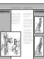 3
3
-
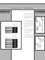 4
4
-
 5
5
-
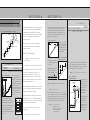 6
6
-
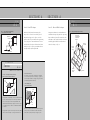 7
7
-
 8
8
-
 9
9
-
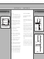 10
10
-
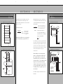 11
11
-
 12
12
-
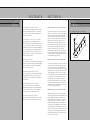 13
13
-
 14
14
-
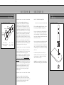 15
15
-
 16
16
-
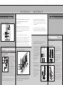 17
17
-
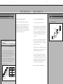 18
18
-
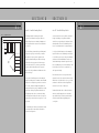 19
19
-
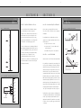 20
20
-
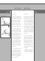 21
21
-
 22
22
-
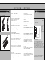 23
23
-
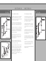 24
24
-
 25
25
-
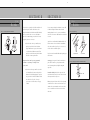 26
26
-
 27
27
-
 28
28
-
 29
29
-
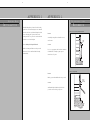 30
30
-
 31
31
-
 32
32
-
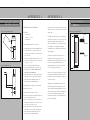 33
33
-
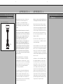 34
34
-
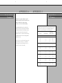 35
35
-
 36
36


Crown Heritage BC419601012 Installation guide
- Type
- Installation guide
Ask a question and I''ll find the answer in the document
Finding information in a document is now easier with AI
Related papers


Other documents
-
Allied Brass WM-6G/5X-BKM Installation guide
-
Allied Brass WM-5G/2X-WHM Installation guide
-
Allied Brass WM-6T/5X-PC Installation guide
-
Allied Brass WM-5D/5X-CA Installation guide
-
Allied Brass WM-5T/2X-SBR Installation guide
-
Allied Brass WM-6D/5X-PNI Installation guide
-
Allied Brass WM-5/5X-SBR Installation guide