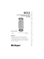
Legrand DCC2 Low Voltage Momentary Switch, Miro Decorator Style Installation guide
- Type
- Installation guide
Legrand DCC2 Low Voltage Momentary Switch, Miro Decorator Style, is a stylish and reliable switch designed for low voltage applications. It features two momentary buttons, a built-in LED, and flexible wiring options. Use it to control lighting, sensors, or other devices with momentary input requirements. Installation is a breeze, and the switch comes with a 5-year warranty for peace of mind.
Legrand DCC2 Low Voltage Momentary Switch, Miro Decorator Style, is a stylish and reliable switch designed for low voltage applications. It features two momentary buttons, a built-in LED, and flexible wiring options. Use it to control lighting, sensors, or other devices with momentary input requirements. Installation is a breeze, and the switch comes with a 5-year warranty for peace of mind.


-
 1
1
-
 2
2
-
 3
3
-
 4
4


Legrand DCC2 Low Voltage Momentary Switch, Miro Decorator Style Installation guide
- Type
- Installation guide
Legrand DCC2 Low Voltage Momentary Switch, Miro Decorator Style, is a stylish and reliable switch designed for low voltage applications. It features two momentary buttons, a built-in LED, and flexible wiring options. Use it to control lighting, sensors, or other devices with momentary input requirements. Installation is a breeze, and the switch comes with a 5-year warranty for peace of mind.
Ask a question and I''ll find the answer in the document
Finding information in a document is now easier with AI
Related papers
-
Legrand LP Series Lighting Control Panel Installation guide
-
Legrand LP24S-4-115 Installation guide
-
-
-
-
-
-
-
-
Other documents
-
 Deltec Protein Skimmer SC 1351 Operating
-
Hitachi SJ2-CO User manual
-
Sony CPD-E400E User manual
-
Black Box AC1032A-4A Datasheet
-
Gateway VX900T User manual
-
Panasonic DMC-LS80 Owner's manual
-
Panasonic DMCLS85 Owner's manual
-
-
-
wattstopper DT-200 Installation Instructions Manual
