Page is loading ...

1
IMPORTANT:
IMPORTANT:
Go to www.extron.com for the complete
user guide, installation instructions, and
specifications before connecting the
product to the power source.
DXP 42 HD 4K PLUS • Setup Guide
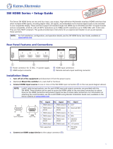
The DXP 42 HD 4K PLUS is a four input, two output HDMI matrix switcher that routes HDMI signals from multiple sources to
HDMI-equipped display devices. It supports computer and video resolutions up to 4K @ 60 Hz. It also supports HDMI 1.n and
2.0b specications, including data rates up to 18.2 Gbps, HDR Deep Color up to 12-bit, 3D, and HD lossless audio formats. The
switcher is HDCP 2.2 and 1.4 compliant, and incorporates Extron technologies including SpeedSwitch
®
, EDID Minder
®
, and Key
Minder
®
. Digital audio can be de-embedded from any input and assigned to independent analog stereo outputs.
This setup guide enables you to quickly set up and congure your DXP 42 matrix switcher. Step-by-step instructions show
you how to connect the hardware and to perform basic operations using both the front panel controls and selected Simple
Instruction Set (SIS) commands. The guide also shows you how to connect to the built-in web page and load and start up the
Product Conguration Software (PCS), which you can also use to congure and operate the switcher. For additional information
and specications, see the DXP HD 4K PLUS product page at www.extron.com.
The terms “DXP,” “DXP 42”, “matrix,” “switcher,” and “DXP 42 matrix switcher” are used interchangeably in this guide to refer to
the DXP 42 HD 4K PLUS.
LAN
LAN
POWER
12V
1.5A MAX
INPUTS
1
HDMI
2
HDMI
3
HDMI
4
HDMI
OUTPUTS
1
HDMI/CEC
2
HDMI/CEC
AUDIO OUTPUTS
L
3
R L
4
R
Tx
RS-232
Rx G
REMOTE
MODEL 80
FLAT PANEL
ShareLink Pro 1000
HD WIN
STANDBY
SCREEN
DECODER
HD PASS
HDMI DECODER
SIGNAL
HDCP
CONFIG
OUTPUTINPUT
HDMI
WINDOW
HDMI
PASS-THROUGH
12
USB
WiFi
1234
LAN
POWER
12V
1A MAX
G
Tx Rx RTSCTS
COM 1
G
Tx Rx
COM 2
VCG
VOL
RELAYS
12C
1 2 3 4G
DIGITAL I/O
PWR OUT =6W
eBUS
+V +S
-S
G
LAN
IPCP PRO250
IR/S
SG
Laptop
Tablet
Smartphone
Wireless Access Point
Videoconferencing PC
Logitech
Rally Mic Pod
4K Display
Logitech
Rally Camera
USB
Ethernet
Ethernet
RS-232
Ethernet
Ethernet
AudioAudio
HDMI
HDMIHDMI
HDMI
HDMIHDMI
Extron
TLP Pro 1025T
10" Tabletop TouchLink
Pro Touchpanel
Extron
IPCP Pro 250
IP Link Pro
Control Processo
r
Extron
SB 33 A
Sound Bar
Ext
ron
ShareL
ink Pro 1000
Wireless
and Wired
Collaboratio
n Gateway
Extron
DXP 42 HD 4K PLUS
4K/60 HDMI Matrix
Switcher with Audio
De-Embedding
Laptop Laptop
USBUSB
HDMI
Capture
Ethernet
Figure 1. Typical Application of the DXP 42 HD 4K PLUS
Setup Steps
Follow these steps to set up and start operating the DXP 42 matrix switcher:
1. Turn off power to the input and output devices that will be connected.
2. Connect HDMI input devices to the rear panel input connectors (see figure 2,
A
, on the next page).
3. Connect HDMI audio and video output devices to the rear panel output connectors: video (
B
), audio (
C
), or both.
4. Connect control devices as desired:
• Connect a computer or control system to the Remote RS-232 (
D
) or the front panel USB Config port (see figure 5,
C
,
on page 4).
• Connect a computer, control system, or network switch to the RJ-45 LAN (Ethernet) port (see figure 2,
E
).
5. Connect the provided 12 V, 1.5 A power supply between the DXP switcher and a 100-240 VAC, 50-60 Hz power source, and
connect power to the input and output devices.
6. Download the PCS program from www.extron.com (see Downloading the Software on page 10).
1

2
DXP 42 HD 4K PLUS Series • Setup Guide (Continued)
7. Select EDID files to apply to inputs as desired, using PCS (see the DXP HD 4K PLUS Series Help file for details).
8. Create ties as desired (see Creating Ties on page 5).
Rear Panel Connections
CAUTION: Remove power from the system before making any connections.
ATTENTION : Couper l’alimentation avant de faire l’installation électrique.
ATTENTION:
• Use electrostatic discharge precautions (be electrically grounded) when making connections. Electrostatic discharge
(ESD) can damage equipment, although you may not feel, see, or hear it.
• Prenez des précautions contre les décharges électrostatiques (soyez électriquement relié à la terre) lorsque vous
effectuez des connexions. Les décharges électrostatiques (ESD) peuvent endommager l’équipement, même si vous ne
pouvez pas le sentir, le voir ou l’entendre.
LAN
POWER
12V
1.5A MAX
INPUTS
1
HDMI
2
HDMI
3
HDMI
4
HDMI
OUTPUTS
1
HDMI/CEC
2
HDMI/CEC
AUDIO OUTPUTS
L
3
R L
4
R
Tx
RS-232
Rx G
REMOTE
FFF
D
D
D
C
C
C
B
B
B
A
AAD
D
D
D
D
DE
E
E
A
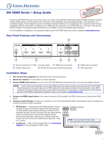
Input connectors
C
Analog audio outputs
E
LAN port
B
Output connectors
D
Remote RS-232 connector
F
Power connector
Figure 2. DXP 42 HD 4K PLUS Rear Panel
A
Input connectors — Connect HDMI (or DVI with an appropriate adapter) sources to these female 19-pin type A
HDMI connectors for video input.
LockIt™ cable lacing brackets, one for each HDMI input and output connector, are provided with the DXP 42 HD 4K PLUS.
These brackets can be used to secure the HDMI cables to the DXP connectors to reduce stress on the HDMI connectors
and prevent signal loss due to loose cable connections (see Securing HDMI Cables with the LockIt HDMI Cable Lacing
Bracket on page 4).
B
Video output connectors — Connect HDMI (or DVI with an appropriate adapter) displays or other output devices
to these female 19-pin type A HDMI output connectors for buffered video output (see Securing HDMI Cables with
the LockIt HDMI Cable Lacing Bracket).
C
Analog audio outputs — Connect powered speakers, an amplifier, or other audio output device to these 5-pole 3.5 mm
captive screw connectors for 2-ch stereo analog audio output. These connectors can provide de-embedded LPCM audio
that was routed from any DXP HDMI input and convert it to a stereo analog signal. Figure 3 shows how to wire these
connectors. Use the supplied tie-wrap to strap the audio cable to the extended tail of the connector.
Do not tin the wires!
Balanced Audio Output
Tip
Ring
Tip
Ring
Slee
ves
Unbalanced Audio Output
Tip
No Ground Here
No Ground Here
Tip
Sleeves
LR
LR
Figure 3. Connecting Analog Audio
ATTENTION:
• For unbalanced audio output, connect the sleeves to the ground contact. DO NOT connect the sleeves to the
negative (-) contacts.
• Pour l’audio asymétrique, connectez les manchons au contact au sol. Ne PAS connecter les manchons aux
contacts négatifs (–).
NOTE: The length of exposed wires is important. The ideal length is 3/16 inch (5 mm).
2
1
1
3

3
D
Remote RS-232 connector — Connect an RS-232 capable host
device such as a computer or a touch panel control to this 3.5 mm
3-pole captive screw connector to configure and control the
switcher via SIS commands. Connect the 9-pin end of the RS-232
cable to the serial port of your computer or control system (see the
diagram at right). The default port parameters are 9600 baud, 8 data
bits, 1 stop bit, no parity.
E
LAN port — Connect a computer, a network switch, or a control
system to this RJ-45 connector (see figure 4 for wiring information).
With the Ethernet connection, you can use a computer to configure
and control the networked switcher with SIS commands, the PCS
configuration program, or the embedded HTML page.
Ethernet connection indicators — The Link and Act
LEDs indicate the status of the Ethernet connection.
• Link — Indicates that the switcher is properly connected to an
Ethernet LAN. This green LED should light steadily.
• Act (Activity) — Indicates transmission of data on the RJ-45
connector. This amber LED should flicker as the switcher
communicates.
Ethernet links use Category (CAT) 3, 5e, or 6 unshielded twisted
pair (UTP) or shielded twisted pair (STP) cables, terminated with RJ-45 connectors. Ethernet cables are limited to 328 feet
(100 meters).
NOTES:
• Do not use standard telephone cables. Telephone cables do not support Ethernet or Fast Ethernet.
• Do not stretch or bend the cables because this can cause transmission errors.
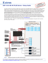
A cable that is wired as T568A at one end
and T568B at the other (Tx and Rx pairs
reversed) is a "crossover" cable.
A cable that is wired the same at both ends
is called a "straight-through" cable because
no pin or pair assignments are swapped.
Both ends of the cable can be T568B (as shown)
or T568A (not shown).
RJ-45
Connector
Insert T
wisted
Pair Wires
12345678
Pins:
Crossover Cable Straight-through Cable
Pin
1
2
3
4
5
6
7
8
Wire Color
White-green
Green
White-orange
Blue
White-blue
Orange
White-brown
Brown
Wire Color
T568A
T568B
End 1 End 2 End 1 End 2
White-orange
Orange
White-green
Blue
White-blue
Green
White-brown
Brown
Pin
1
2
3
4
5
6
7
8
Wire Color
Blue
White-blue
White-brown
Brown
Wire Color
T568B
T568B
White-orangeWhite-orange
OrangeOrange
White-greenWhite-green
Blue
White-blue
GreenGreen
White-brown
Brown
Figure 4. RJ-45 Connector and Pinout Tables
The cable you use depends on your network speed. The switcher supports both 10 Mbps (10Base-T — Ethernet) and
100 Mbps (100Base-T — Fast Ethernet), half-duplex and full-duplex Ethernet connections.
• 10Base-T Ethernet requires CAT 3 or higher UTP or STP cables.
• Fast Ethernet requires CAT 5e or higher UTP or STP cables.
Terminate the Ethernet cable as required:
• Network connection — Wire as a patch (straight-through) cable.
• Computer or control system connection — Wire as a crossover cable.
F
Power connector — Plug the provided external
12 VDC, 1.5 A power supply into this 2-pole, 3.5 mm
captive screw connector and into an AC power outlet
(see the diagram at right for wiring).
Computer or
Control System
RS-232 Port
DXP 42 HD 4K PLUS
Rear Panel
RS-232 Port
NOTES:
• If you use cable that has a drain wire, tie
the drain wire to ground at both ends.
• Connect a ground wire between the DXP
and the computer or control system.
Tx Rx G
Tx Rx
G
Ground (G)
Transmit (Tx)
Receive (Rx)
Transmit (Tx)
Receive (Rx)
Default Ethernet settings:
• IP address — 192.168.254.254
• Subnet mask — 255.255.0.0
• Gateway address — 0.0.0.0
SECTION A–A
Ridges
Smooth
A
A
3/16"
(5 mm) Max.
POWER
12V
1.5 A MAX

4
DXP 42 HD 4K PLUS Series • Setup Guide (Continued)
Securing HDMI Cables with the LockIt HDMI Cable Lacing Bracket
Use a LockIt HDMI Cable Lacing Bracket to securely fasten each HDMI cable to the switcher:
1. Plug the HDMI cable into the panel connection (see the illustration at right,
1
).
2. Loosen the HDMI connection mounting screw from the panel enough to allow the LockIt
lacing bracket to be placed over it (
2
). The screw does not have to be removed.
3. Place the LockIt lacing bracket (
3
) on the screw and against the HDMI connector, then
tighten the screw to secure the bracket.
ATTENTION:
• Do not overtighten the HDMI connector mounting screw. The shield it fastens to
is very thin and can easily be stripped.
• Ne serrez pas trop la vis de montage du connecteur HDMI. Le blindage auquel
elle est attachée est très fin et peut facilement être dénudé.
4. Loosely place the included tie wrap around the HDMI connector and the LockIt lacing bracket as shown (
4
).
5. While holding the connector securely against the lacing bracket, use pliers or similar tool to tighten the tie wrap, then remove
any excess length.
Front Panel Features
The front panel buttons have primary and secondary functions. The table on the next page contains descriptions of some of the
basic functions. For more details, see the DXP HD 4K PLUS Series User Guide, available at www.extron.com. Each button has
an LED beside it. These bicolor LEDs light green when video is selected and red when audio is selected.
F
F
F
D
D
D
CONFIG
R
DXP 42 HD 4K PLUS
INPUTS
INPUTS
OUTPUTS
SIGNAL
HDCP
1 2 1 2
1234
3 4
A
A
A
B
B
B
GGG
C
C
C
D
D
D
E
E
E
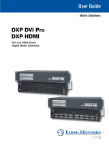
A
Power and Reset LED
C
Config port
E
Output buttons
G
HDCP LEDs
B
Reset button
D
Input buttons
F
Signal LEDs
Figure 5. DXP 42 HD 4K PLUS Front Panel
A
Power and Reset LED — This green LED lights steadily while the switcher has power.
In addition, while you are holding the Reset button, the LED blinks every 3 seconds to indicate the level of reset that will
occur if the button is released at that point.
B
Reset button — This recessed button initiates four levels (modes) of reset. Use a pointed object such as a small
screwdriver to press and hold the Reset button.
• Factory firmware reset (mode 1) — Hold the Reset button while powering up the switcher to restore the DXP to
the factory firmware for a single power cycle. This type of reset maintains all the current user settings, such as audio
adjustments, IP settings, and the configuration.
• IP settings reset (mode 4) — While the DXP is running, press and hold the Reset button until the LED blinks twice
(approximately 6 seconds). Release the button and press it again momentarily to reset the switcher IP settings.
• Absolute reset (mode 5) — While the DXP is running, press and hold the Reset button until the LED blinks three
times (approximately 9 seconds). Release the button and press it again momentarily to restore the switcher to the
default factory conditions. This reset, equivalent to the
E
ZQQQ
}
SIS command, removes the initial serial number
passwords that are set at the factory and resets them to no password.
NOTE: The factory configured passwords for all accounts on this device have been set to the device serial number.
In the event of a complete system reset (Mode 5), the passwords convert to the default, which is no password.
3
33
11
44
22
4
RESET

5
C
Config port — This USB mini-B port serves a similar communications function to the rear panel Remote RS-232 port, but is
easier to access than the rear port after the matrix switcher has been installed and cabled. Use a USB type A to mini B cable
to connect this port to a USB connector on the computer to enable SIS commands to be sent from the computer, connection
to the PCS configuration software, and uploading firmware.
Front Panel Button Functions
Primary Function Secondary Functions
D
Input buttons
Select inputs. View ties.
E
Output buttons
Select outputs. View ties.
F
Signal LEDs — The DXP has a green Signal LED for each input. Each LED lights when a signal (TMDS clock activity) is
present on the input.
G
HDCP LEDs — The DXP has a green HDCP LED for each input. Each of these LEDs lights if the source connected to its
input is HDCP encrypted.
Operation
Creating Ties
A tie is an input-to-output connection. Ties can be made using the front panel buttons, SIS commands, or PCS. You can tie an
input to one or more outputs.
NOTES:
• A "Set of ties" is an input tied to two or more outputs. (An output can never be tied to more than one input.)
• A "Configuration" is one or more ties, one or more sets of ties, or a combination.
• Audio ties can be made only with de-embedded audio.
• Audio ties cannot be made using the front panel buttons. However, they can be created using PCS or SIS commands.
To make ties:
1. Press an input button on the front panel (see the illustration at right). The LED next to it lights.
• If the selected input is already tied to one or more outputs, the tied output LEDs light.
• If you press the tied output button, the output is disconnected (untied) from the input.
2. Within 5 seconds, press the output button or buttons to which the
input is to be tied. All selected output LEDs light, then turn off after 5
seconds. The illustration at right shows a tie between input 1 and
output 1.
NOTE: If no output is selected within 5 seconds, the input LED
turns off and no tie is made to the input.
To break existing ties:
1. Press the button for the input to be untied. The LEDs for the tied outputs light.
2. Press the output button to be untied. The output button LED turns off, indicating that the tie is broken.
Viewing Ties
• To view ties to an input: Press the desired input button.
The button LEDs light for all outputs that are tied to that input.
The illustration at right shows a tie between input 1 and
output 1. Pressing the input 1 button causes its LED to light.
The output 1 button LED also lights, indicating that a tie exists
between input 1 and output 1.
• To view ties to an output: Press the desired output button.
The LED for the selected output button lights. In addition, the
button LEDs for the tied input and for all outputs tied to that
input light.
1
The LED lights to
indicate the selection.
The input LED lights to
indicate the selected input.
The output LED lights to
indicate the output is tied to
the selected input.
1
1
After 5 seconds, all LEDs turn off.
Input
Output
INPUTS
OUTPUTS
1 2 1 23 4
Press an output button.
The output button LED lights.
The tied input button LED lights.

6
DXP 42 HD 4K PLUS Series • Setup Guide (Continued)
Locking and Unlocking the Front Panel (Executive Mode)
Lock mode (executive mode) limits control of the DXP 42 from the front panel, so that functions such as input switching and
output muting are not allowed from the front panel. The executive mode selection remains in effect after a power cycle.
The matrix switcher front panel buttons can be locked and unlocked using the following SIS commands (see the Front Panel
Lock (Executive) Modes commands on page 8 for information on issuing SIS commands to the unit):
• To lock the front panel buttons, enter 1X.
• To unlock the front panel, enter 0X.
Remote Configuration and Control
You can send SIS commands over an Ethernet link (rear panel RJ-45 LAN port, see figure 2,
E
, on page 2), a serial connection
(rear panel Remote RS-232 port,
D
), or USB (front panel Cong port, see figure 5,
C
, on page 4). The network connection
procedure is described below. For information about the serial and USB connections, as well as a complete list of the available
SIS commands, see the DXP HD 4K PLUS Series User Guide, available at www.extron.com.
Establishing a Network (Ethernet) Connection
To establish a network connection:
1. Open a TCP socket to port 23 using the switcher IP address.
NOTE: The factory default IP address is 192.168.254.254. You can change this address using SIS commands,
the PCS configuration software, or the internal web page (see the DXP 42 HD 4K PLUS User Guide, available at
www.extron.com, for instructions).
The switcher responds with a message consisting of the copyright date, the name of the product, rmware version, part
number, and the current date and time. For example, with an internet connection:
(c) Copyright 20nn, Extron Electronics, DXP 42 HD 4K Plus, Vn.nn, 60-1678-01
]
Ddd, DD Mmm YYYY HH:MM:SS
]
NOTES:
• If the switcher is not password-protected, the device is now ready to accept SIS commands.
• If the switcher is password-protected, a password prompt appears.
2. If the switcher is password-protected, enter the password.
NOTE: The factory configured passwords for all accounts on this device have been set to the device serial number. In
the event of a complete system reset (Mode 5), the passwords convert to the default, which is no password.
3. If the password is accepted, the switcher responds with Login User or Login Administrator.
4. If the password is not accepted, the Password prompt reappears (see your network admin for the assigned password).
Connection timeouts
The Ethernet link times out and disconnects after a designated period of no communications. By default, this timeout value is set
to 5 minutes but the value can be changed.
NOTE: Extron recommends leaving the default timeout at 5 minutes and periodically issuing the Query (Q) command to keep
the connection active or disconnecting the socket and reopening the connection when necessary.
Number of connections
A switcher can have up to 200 simultaneous TCP connections, including all HTTP sockets and Telnet connections. When
the connection limit is reached, the switcher accepts no new connections until some have been closed. No error message or
indication is given that the connection limit has been reached. To maximize performance of your switcher, keep the number of
connections low and close unnecessary open sockets.
SIS Commands
The switchers have SIS commands that you can use for operation and conguration. You can issue these commands from a
PC or control system connected to the DXP serial port, USB port, or Ethernet port (see Rear Panel Connections on page 2 for
connection information).

7
Host-to-switcher instructions
The switcher accepts SIS commands through the LAN port, the Remote (RS-232) port, or the front panel USB Cong port. SIS
commands consist of one or more characters per command eld. They do not require any special characters to begin or end
the command character sequence. Each switcher response to an SIS command ends with a carriage return and a line feed
(CR/LF =
]
), which signals the end of the response character string. A string is one or more characters.
NOTE: Input and output numbers in commands can be entered as one-digit, two-digit, or three-digit numbers. All input and
output numbers are reported as two-digit numbers in the response.
Verbose mode
Telnet connections to a switcher can be used to monitor for changes that occur on the switcher, such as front panel operations
and SIS commands from other Telnet sockets or a serial port. For a Telnet session to receive change notices from the switcher,
the Telnet session must be in verbose mode 1 or 3 (see the Set verbose mode command on page 9).
NOTE: If tagged responses is enabled (modes 2 and 3), all view commands return the same constant string and the value
as the set command does (for example, the view matrix name command
E
CN
}
, returns Ipn •
X3)
]
).
Symbol definitions
]
= Carriage return and line feed
}
or | = Carriage return (no line feed)
• = Space
E
or W = <Escape> key
X!
= Input number 0 through 4 (0 = untied)
X@
= Output number 0 through 2 (0 = untied)
If the audio output number entered is greater than 4, an E12 error code
(Invalid output number) is returned.
X#
= On or off (enable or disable) 0 = Off or disable, 1 = on or enable
X%
= Analog audio output number 3 or 4.
X*
= Output format 0 = Auto (default) 4 = HDMI YUV 4:4:4 Full
1 = DVI RGB 4:4:4 Full 5 = HDMI YUV 4:4:4 Limited
2 = HDMI RGB 4:4:4 Full 6 = HDMI YUV 4:2:2 Full
3 = HDMI RGB 4:4:4 Limited 7 = HDMI YUV 4:2:2 Limited
X1@
= Video and sync mute status 0 = Video and sync unmuted
1 = Video muted
2 = Video and sync muted
X1#
= Audio mute status 0 = Audio unmuted
1 = HDMI audio muted
2 = Analog audio muted
3 = HDMI and analog audio muted
X2)
= Front panel lock mode status 0 = Lock mode 0: Front panel unlocked (default)
(executive mode) 1 = Lock mode 1: Front panel locked
X2#
= Verbose mode 0 = Clear or none (default for Telnet connection)
1 =Verbose mode (default for RS-232 and USB connections)
2 = Tagged responses for queries
3 = Verbose mode and tagged responses for queries
X2%
= Firmware version (n.nn) Shown to second decimal place
X2^
= Firmware and build version Example: 1.00.0000-b003
X3)
= IP address nnn.nnn.nnn.nnn
X3!
= Subnet mask nnn.nnn.nnn.nnn
X3@
= Gateway address nnn.nnn.nnn.nnn
X3%
= Port timeout 1 to 65000 in 10-second intervals (30 = default)
NOTES:
• Commands can be entered back-to-back in a string, with no spaces. For example: 1*1!02*02&003*003%4*8$.
• The matrix switchers support 1-, 2-, and 3-digit numeric entries (1*1!,02*02&, or 003*003%).

8
DXP 42 HD 4K PLUS Series • Setup Guide (Continued)
Command and Response Table for SIS Commands
Command Function
ASCII Command
(Host to Switcher)
Response
(Switcher to Host)
Additional Description
Output Switching (Ties)
Tie HDMI input to HDMI output (video
and audio).
X!
*
X@
! Out
X@
•In
X!
•All
]
Tie HDMI input
X!
to HDMI output
X@
,
video and audio.
Example
1*2!
Out2•In1•All
] Tie input 1 to output 2, video and audio.
Tie an input to all outputs, audio and
video
X!
*! In
X!
•All
]
Tie input
X!
to all outputs, audio and
video.
Video Mutes
Set video mute for an output
X@
*
X1@
B Vmt
X@
*
X1@]
Set video mute on output
X@
to
X1@
.
Set video mute for all outputs
X1@
*B Vmt
X1@]
Set video mute on all outputs to
X1@
.
View video mute status for an output
X@
B
X1@]
View mute status
X1@
for output
X@
.
Unmute video and sync for an output
X@
*0B Vmt
X@
*0
]
Unmute video and sync on output
X@
.
Unmute video for all outputs
0*B
Vmt0
]
Unmute HDMI video on all outputs.
Audio Mutes
NOTE: Audio mute commands affect both HDMI and analog audio, depending on the output from which the audio was
de-embedded.
Mute audio on an output
X@
*
X1#
Z Amt
X@
*
X1#]
Set audio mute for output
X@
to
X1#
.
Mute all audio
X1#
*Z Amt
X1#]
Set audio mute for all outputs to
X1#
.
View audio mute status of an output
X@
*Z
X1#]
View mute status
X1#
for output
X@
.
Unmute audio on an output
X@
*0Z Amt
X@
*0
]
Unmute audio for output
X@
.
Unmute all audio
0*Z
Amt0
]
Unmute audio for all outputs.
Front Panel Lock (Executive) Modes
NOTE: See Locking and Unlocking the Front Panel (Executive Mode) on page 6 for more information on the lock modes.
Set front panel lock mode
X2)
X Exe
X2)]
Set the front panel lock mode to
X2)
.
View lock status
X
X2)]
Display current lock mode
X2)
.
KEY:
X!
= Input number
0 through 4 (0 = untied)
X@
= Output number 1 or 2 (0 = untied). If the audio output number entered is greater than 2, an
E12 error code (Invalid output number) is returned.
X1@
= Video mute status 0 = video and sync unmuted, 1 = HDMI video muted,
2 = video and sync muted,
3 = HDMI and analog audio muted
X1#
= Audio mute status 0 = audio unmuted, 1 = HDMI audio muted, 2 = analog audio muted,
3 = HDMI and analog audio muted
X2)
= Front panel lock mode 0 = unlocked (default), 1 = locked
Information Requests
General information request
I
V04X02•A04X02
]
Show the number of video and audio
inputs (04) and outputs (02).
On the DXP 42 HD 4K PLUS, the matrix
is four video and audio inputs by two
video and audio outputs (outputs 3 and
4 are de-embedded analog audio only
outputs).
Query part number
N
60-1678-01
]
In verbose modes 2 and 3:
Pno60-1678-01

9
Command Function
ASCII Command
(Host to Switcher)
Response
(Switcher to Host)
Additional Description
Information Requests (continued)
Query rmware version
Q
X2%]
View the unit rmware version to the
second decimal place.
In verbose modes 2 and 3:
Ver01*
X2%
Query rmware and build version
*Q
X2^]
View unit rmware version and build
number
X2^
.
In verbose modes 2 and 3:
Bld01*
X2^
IP Setup
Set IP address
E
X3)
CI
}
Ipi
X3)]
Set the unit IP address to
X3)
.
View IP address
E
CI
} X3)]
View unit IP address.
Set subnet mask
E
X3!
CS
}
Ips
X3!]
Set the subnet mask for the unit to
X3!
.
View subnet mask E
CS
} X3&] View the subnet mask.
Set gateway IP address E
X3@
CG
}
Ipg
X3@]
Set the unit gateway address to
X3@
.
View gateway IP address E
CG
} X3@] View the unit gateway address.
Set DHCP on and off
E
X#
DH
}
Idh
X#]
Set DHCP to
X#
.
View DHCP on/off status E
DH
} X#] View the DHCP setting.
Congure current port timeout
E
0*
X5*
TC
}
Pti0*
X5*]
Set the current port timeout to
X5*
.
Read current port timeout
E
0TC
} X5*]
View the current port timeout setting.
Congure global IP port timeout
E
1*
X5*
TC
}
Pti1*
X5*]
Set the global IP port timeout to
X5*
.
Read global IP port timeout
E
1TC
} X5*]
View the global IP port timeout setting.
Set verbose mode E
X5#
CV
}
Vrb
X5#]
Set the verbose mode and tagged
responses to
X5#
.
Read verbose mode E
CV
} X5#] View the current verbose mode.
KEY:
X#
= On or off (enable or disable) 0 = DHCP disabled (default), 1 = DHCP enabled
X2%
= Firmware version number Expressed to the second decimal place (n.nn)
X2^
= Firmware version and build number n.nn.nnnn
X3)
= IP address nnn.nnn.nnn.nnn (Default = 192.168.254.254)
X3!
= Subnet mask nnn.nnn.nnn.nnn (Default = 255.255.0.0)
X3@
= Gateway IP address nnn.nnn.nnn.nnn (Default = 0.0.0.0)
X5#
= Verbose mode 0 = clear or none (default for Telnet connection)
1 = verbose mode (default for RS-232 and USB connection)
2 = tagged responses for queries
3 = verbose mode and tagged for queries
X5*
= Port timeout interval 1 (10 seconds) – 65000 (default is 30 = 300 seconds = 5 minutes)
Reset
System reset to factory defaults
E
ZXXX
}
Zpx
]
Clear all ties and presets and reset unit
to factory default settings.
NOTE: This command excludes IP settings such as IP address and subnet mask. It does not remove the file system.
Absolute system reset
E
ZQQQ
}
Zpq
]
Clear all ties and reset unit to factory
default settings.
NOTES:
• This command includes resetting the IP address to 192.168.254.254 and the subnet mask to 255.255.0.0. The firmware
version remains the same.
• The factory configured passwords for all accounts on this device have been set to the device serial number. Passwords are
case sensitive. In the event of an absolute system reset, the passwords convert to the default, which is no password.

10
DXP 42 HD 4K PLUS Series • Setup Guide (Continued)
Installing and Starting the Configuration Software
The Extron Product Conguration Software (PCS) is a Windows-based program for the DXP 42 HD 4K PLUS that enables you to
congure the input and output, audio, and image settings. It also lets you save and recall presets, select EDID, and perform nearly
all the other functions that can be accomplished via the front panel controls or SIS commands.
NOTE: EDID selection is available only through PCS. When the DXP is connected to PCS, the power save mode is reset to 0
(power save off).
Downloading the Software
To use PCS, download the program from www.extron.com and install it on the PC that will be connected to the DXP:
1. Open the Extron web page and select the Download tab (see figure 6,
1
).
Figure 6. Software Link on the Download Tab
2. Move the mouse pointer to the Software link (
2
) in the Downloads column and click it.
3. On the Download Center Software page, click the P (see figure 7,
1
).
Figure 7. PCS Download Link
4. On the Login page, enter the requested information. If you need an ID number, contact your Extron representative.
5. Follow the instructions on the subsequent screens to download the program. By default the installation creates a folder called
“Extron PCS” at c:\Program Files (x86)\Extron\Extron PCS or c:\Program Files\Extron\Extron PCS. If there is not
already an Extron folder in your Program Files x86 folder, the installation program creates it.
Starting the configuration program
1. Connect the DXP 42 HD 4K PLUS to your computer via USB (front panel Config port) or TCP/IP (rear panel LAN port).

11
2. To run the PCS configuration program, do either of the following:
• Double-click on the EAF.exe file on the computer at c:\Program Files [or Program Files(x86)]\Extron\Extron PCS.
• Click Start on the computer screen and select All Programs > Extron Electronics > Extron Product
Configuration Software > Extron Product Configuration Software.
3. The PCS main window opens with a Tutorial screen that points out significant items on the PCS window. When ready to
proceed, click OK to close the tutorial. The Device Discovery screen opens, with a list of Extron devices connected to your
network (see figure 8).
Figure 8. PCS Window
4. If your DXP device name is displayed in the Device
Discovery panel, select it and click the Connect button.
If the device name is not listed but the IP address is known:
a. Click the TCP/IP tab in the left panel (see
1
in the
illustration at right).
b. Enter the IP information on the TCP/IP screen (
2
).
c. Click the Connect button at the bottom of the screen.
5. The DXP 42 HD 4K PLUS device tab and main screen is displayed in the PCS window. When the screen opens, it displays the
EDID Minder screen. To display other screens, click the icons on the toolbar.
For more information
For further assistance with using PCS with the DXP, see the DXP 42 HD 4K PLUS PCS Help le. To access this le:
1. On the DXP 42 HD 4K PLUS main window, click the down arrow on the device tab for your DXP. The Device drop-down
menu is displayed.
2. From the drop-down menu select DXP <model number> HD 4K PLUS Help.
Accessing the Web Page
The embedded DXP 42 HD 4K PLUS web page enables you to monitor and adjust certain settings of the DXP through its Ethernet
port, connected via a LAN or WAN and using a web browser. This factory-installed web page cannot be erased or overwritten. For
details on the DXP 42 HD 4K PLUS web page, see the DXP HD 4K PLUS Series User Guide, available at www.extron.com.
NOTE: If your Ethernet connection to the DXP is unstable, try turning off the proxy server in your web browser. To do this
in Microsoft Internet Explorer, click Tools > Internet Options > Connections > LAN Settings, clear the Use a proxy
server... checkbox, then click OK.
1. In the Address field of your web browser, enter the IP address of your unit, and press <Enter>.

68-2939-51 Rev. A
01 20
DXP 42 HD 4K PLUS Series • Setup Guide (Continued)
© 2020 Extron Electronics All rights reserved. All trademarks mentioned are the property of their respective owners. www.extron.com
2. If the unit is not password protected, the web page opens. If the Authentication Required dialog box opens, enter the user
name (admin, by default) in the User Name field and the password in the Password field. Click Log In. The DXP 42 HD 4K
PLUS web page contains the following panels:
1
Device Info — Displays device name, brief product description, and part number. The panel also contains an Extron
link, which opens www.extron.com in a new window. To assign a new name to the device, click the EDIT link.
2
Inputs — Displays the name and signal type of the active input signal as well as its HDCP status. To view the status and
type of all inputs, click the 2 MORE link in the lower-left corner of the panel to view the Inputs dialog box
3
RS-232 — (View-only) Displays the RS-232 protocol baud rate, parity bits, data bits, and stop bits.
4
Device Status — Displays the current date, time, time zone, the amount of time the device has been running (Uptime).
Click the EDIT link to edit these settings or the SYNC TO PC link to sync the settings to those of your PC.
5
Outputs — Displays the signal type (HDMI, DTP, or DVI), and the HDCP status of all connected outputs.
6
Roles and Permissions — Click the EDIT link to enter a new password or change the current one. The factory
configured passwords for all accounts on this device have been set to the device serial number.
7
Network Settings — Click EDIT to set the IP address, DHCP setting, subnet mask, and gateway address for your DXP.
8
Firmware — Displays the current firmware version and the date it was last updated. You can also update the firmware
on your unit here by clicking the SELECT FILE button (firmware files can be downloaded from www.extron.com).
Figure 9. DXP 42 HD 4K Plus Web Page
For information on safety guidelines, regulatory compliances, EMI/EMF compatibility, accessibility, and related topics, see the
Extron Safety and Regulatory Compliance Guide on the Extron website.
/