Page is loading ...

Mirage Shower Door & Base Kit
S
HOWER
Door
AND
S
HOWER
B
ASE
KIT I
NSTALLATION
I
NSTRUCTIONS
IMPORTANT
DreamLine
TM
reserves the right to alter, modify or redesign products at any time
without prior notice. For the latest up-to-date technical drawings, manuals or any
other details please refer to the support.BathAuthority.com
web page.
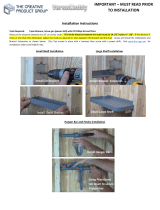
STEP 1: Install Shower Base
Shower Base Installation Instructions
STEP 2: Install Shower Door
Shower Door Installation Instructions
Please read these instructions carefully before installing. If you have any questions regarding
installation, please call our technical support specialists Monday through Friday 9:00 AM – 5:00
PM EST at Phone:
1-866-731-2244, Fax: 1-866-227-1533 or e-mail our technical support
group at
support@BathAuthority.com.
For more information on DreamLine Shower Kit please visit www.BathAuthority.com

MIRAGE
SHOWER DOOR & TUB DOOR INSTALLATION INSTRUCTIONS
IMPORTANT
DreamLine
TM
reserves the rights to alter, modify or redesign products at any time without prior
notice. For the latest up-to-date technical drawings, manuals or any other details please refer
to the support.BathAuthority.com web page.
Please read these instructions carefully before installing. If you have any questions regarding
installation, please call our technical support specialists Monday through Friday 9:00 AM – 5:00
PM EST at Phone: 1-866-731-2244, Fax: 1-866-227-1533 or e-mail our technical support group
For more information on DreamLine Shower Doors and Tub Doors please visit www.BathAuthority.com

“MIRAGE – 60” Rev. 2 Ver. 5 07/2013 2
Preparation
1. After opening all boxes and packages, read this introduction carefully. Check that all of the needed
parts are included in the package by marking all the components on the “Detailed Diagram of
Shower Door Components”. Examine boxes and packages for shipping damage. If the unit has
been damaged, has a finishing defect, or is missing parts, please contact our customer support
department within 5 business days of the delivery date. Please note that DreamLine
TM
will not
replace any damaged products or missing parts free of charge after 5 business days or if the
product has been installed. Feel free to contact DreamLine
TM
if you have any questions.
2. Please note that you should consult your local building codes with questions on installation
compliance standards. Building and plumbing codes may vary by location, and DreamLine is
not responsible for code compliance standards for your project and will not accept any
returns.
3. If this unit is going to be installed in a new construction, install all of the required plumbing and
drainage before installing the shower. Use a competent and licensed (if required by local code)
plumber for all plumbing installation.
4. Prior to installation, ensure that the installation surface is leveled and solid and will be able to
support the total weight of the unit. Also, make sure the walls are at right angles. Irregular
installation surface level or improper angle of side walls will result in serious problems for your
installation. Please, note that some adjustments and drilling might be necessary during the
installation process.
5. This unit must be installed against finished walls and floor.
6. Please, NOTE! This door does not have out-of-plumb adjustment. Make sure your walls are
vertical and your shower base or threshold is leveled.
Tools Required
Caulk
Tape
Measure Pencil
Screwdriver
Phillips
Level
Gun
Caulk
Drill
Electric
Hammer
Wrench
Drill bit
(Ø 5/16")

“MIRAGE – 60” Rev. 2 Ver. 5 07/2013 3
Detailed Diagram of Shower/Tub Door Components
6
1
2
20
19
3
4
5
16
7
8
9
10
11
17
18
12
14
13
15
Parts List
01 Stationary glass A 1pc 11 Stopper block 1pc
02 Glass door 1pc 12 Wall bracket 2pcs
03 Guide rail 1pc 13 Single side strip 1pc
04 Handle 1pc 14 Bumper strip 1pc
05 Support bar 1pc 15 Seal gasket 1pc
06 Wall anchor 6pcs 16 Countersunk screw ST4.2×40 1pc
07 Round head screw ST4.2×55 6pcs 17 Shelf bracket (without nut) 4pcs
08 Guide rail connector 1pair 18 Shelf bracket (with nut) 2pcs
09 Sliding bracket assembly 1pc 19 Glass shelf 2pcs
10 Roller assembly 2pcs 20 Stationary glass B 1pc
NOTE: Unpack your unit carefully and inspect it. Lay it out and identify all parts using parts diagram
and part list in your manual as a reference. Before discarding the carton, check for small hardware
bags that tend to fall to the bottom of the box. If any parts are damaged or missing, please contact
DreamLine
TM
for replacement.
NOTE: Retain these installation instructions for future reference.

“MIRAGE – 60” Rev. 2 Ver. 5 07/2013 4
Sliding Bracket Assembly
A Face Plate 1pc F Head screw M4×10 2pcs
B Back Plate 1pc G Head screw M6×16 2pcs
C Slider 1pc H Head screw M6×8 1pc
D 1/16” PVC gasket 2pcs I 1/8” wool strip 4pcs
E 1/16” PVC washer 2pcs J Plastic bulkhead 8pcs
A
C
D
E
G
B
H
I
J
F

“MIRAGE – 60” Rev. 2 Ver. 5 07/2013 5
Shower/Tub Door Installation
NOTE: The installation of this door requires
two installers.
NOTE: The door can be installed on the
shower base, tub or custom threshold.
1. Measure the distance between two walls.
This distance is marked as “W”.
See Fig. 1 for details.
Fig. 1
2. Your Guide rail (03) has been precut for your
Shower model opening width: 60”.
If W-width of your wall-to-wall opening is equal
to 60” it is unnecessary to cut the Guide rail and
you can continue to Step#3.
If W-width of your wall-to-wall opening is less
than 60” you will need to cut the Guide rail from
one side.
The length to cut off will be D:
D=Subtract W from 60”
See Fig. 2 for details.
Fig. 2
W
D
FOR EXAMPLE
If your wall opening W=59”. Your shower
model is 60”.
D=60”-59”=1”,
You have to cut 1” off from the rail.

“MIRAGE – 60” Rev. 2 Ver. 5 07/2013 6
3. Fasten the Guide rail connector (08) to one
of the sides of the Guide rail (03).
Slide in two Roller assemblies (10) from the
other end of the Guide rail. Fasten another
Guide rail connector to the other side of
the Guide rail.
Position the Guide rail on base or threshold
and trace through predrilled holes of Guide
rail connector flange to mark wall. Drill the
holes using Ø 5/16” drill bit and insert the
Wall anchor (06).
Apply a layer of waterproof silicone to the
bottom side of the Guide rail. Place the
Guide rail back on base or threshold and
secure it with the Round head screw
ST4.2×55 (07).
See Fig. 3 for details.
Fig. 3
4. View of the installed Guide rail (03) with the
Guide rail connectors (08).
See Fig. 4 for details.
Fig. 4
Ø 5/16
8
7
6
5
4
3
2
1

“MIRAGE – 60” Rev. 2 Ver. 5 07/2013 7
5. Mount the Wall bracket (12) to Stationary
glass A (01).
Slide the glass into the channel of the Guide
rail (03).
See Fig. 5 for details.
Fig. 5
6. Butt up Stationary glass A (01) against the wall
and level it vertically.
See Fig. 6 for details.
Fig. 6
3
2
1

“MIRAGE – 60” Rev. 2 Ver. 5 07/2013 8
7. Outline the position of the Wall bracket (12) on the
wall. Set Stationary glass A (01) aside. Remove the
Wall bracket from Stationary glass A and by
replacing it to the outlined position mark the hole
on the wall.
Drill the hole using Ø 5/16” drill bit, insert the Wall
anchor (06) and fasten the Wall bracket to the wall
with the Round head screw ST4.2×55 (07).
Put Stationary glass A back into position and tight
it up to the Wall Bracket.
See Fig. 7 for details.
Fig. 7
8. Mount the Wall Bracket (12) on Stationary glass B
(20).
Slide the glass into the channel on the other side of
the Guide rail (03).
See Fig. 8 for details.
Fig. 8
Ø 5/16”
6
5
4
3
2
1
3
2
1

“MIRAGE – 60” Rev. 2 Ver. 5 07/2013 9
9. Butt up Stationary glass B (20) against the wall
and level it vertically.
See fig. 9 for details.
Fig. 9
10. Outline the position of the Wall bracket (12) on the
wall. Set Stationary glass B (20) aside. Remove the
Wall bracket from Stationary glass B and by
replacing it to the outlined position mark the hole on
the wall.
Drill the hole using Ø 5/16” drill bit, insert the Wall
anchor (06) and fasten the Wall bracket to the wall
with the Round head screw ST4.2×55 (07).
Put Stationary glass B back into position and tight it
up to the Wall Bracket.
See Fig. 10 for details.
Fig. 10
Ø 5/16”
6
5
4
3
2
1

“MIRAGE – 60” Rev. 2 Ver. 5 07/2013 10
11. Push the Single side strip (13) between the groove of the
Guide rail (03) and both Stationary glasses A & B using
wooden shims or other piece of wood.
See fig. 11 for details.
Fig. 11
12. Glass shelves (19) are installed to Stationary
glass B (20).
Mark the Glass shelf position on the wall.
According to the measurements in Fig. 12.1,
mark drill holes for the shelf brackets.
Drill the holes using Ø 5/16” drill bit and insert
the Wall anchors (06).
Attach the Shelf brackets without nut (17) to
the wall with Countersunk screw ST4.2×40
(16) and attach Shelf brackets with nut (18)
to Stationary glass B.
Insert the Glass shelf into the Shelf brackets
and tighten the screws at the bottom of the
brackets.
Start installation with top Glass shelf and
repeat this step to install the bottom Glass
shelf.
See Fig. 12 and Fig. 13 for details.
Fig. 12
2
3
/
8
"
1
0
"
2
1
6
5
4
3
2
1
Ø 5/16”

“MIRAGE – 60” Rev. 2 Ver. 5 07/2013 11
Fig. 13
NOTE: Please refer to Sliding bracket assembly (09) diagram
on Page 4.
13. Disassemble the Sliding bracket assembly.
Mount the Face Plate (A) and Back Plate (B) on the top of
Stationary glass A (01) with the Head screw M6×16 (G).
Use PVC gasket (D) and PVC washer (E) in between glass and
metal parts.
NOTE: Use only hand tools. Do not over tighten the screws.
See Fig. 14 and Fig. 15 for details.
Fig. 14
1
2

“MIRAGE – 60” Rev. 2 Ver. 5 07/2013 12
Fig. 15
14. Install the Stopper block (11) on the bottom of
the Glass door (02).
See fig. 16 for details.
Fig. 16
1
2

“MIRAGE – 60” Rev. 2 Ver. 5 07/2013 13
15. Bring the Glass door (02) inside the shower.
Remove nuts from the Roller assembly (10)
bolts and spread the rollers against the
installation holes on the Glass door. Fasten
the Roller assembly to the Glass door
through the predrilled holes.
NOTE: Steps 15 and Steps 16 require
second person to hold Glass door. The
Glass door will not stay by itself until you
finish the Step 16.
See Fig. 17 for details
Fig. 17
NOTE: Please refer to Sliding bracket assembly (09) diagram on
Page 4.
16. Place the Slider (C) over the top edge of the Glass door (02) and
put the Sliding bracket assembly together using Head screw M4
×10 (F).
NOTE: Sliding bracket assembly (09) can be installed for either
left or right hand configurations. These directions are written
for right-hand configuration; See Page 17 for left hand
configuration.
See Fig. 18 and Fig. 19 for details.
Fig. 18
1
2
3
4
1
2
3

“MIRAGE – 60” Rev. 2 Ver. 5 07/2013 14
Fig. 19
17. Press the Magnetic strip (14) on
the vertical edge of the Glass door
(02) and Stationary glass B (20).
Push the Seal gasket (15) into the
channel of the Guide rail (03).
See Fig. 20 for details.
Fig. 20
1
2
3
4

“MIRAGE – 60” Rev. 2 Ver. 5 07/2013 15
18. Install the Handle (04) onto the Glass door (02).
See fig. 21 for details.
Fig. 21
19. Locate the Support bar (05) and temporarily fasten
it to the Sliding bracket assembly (09) with the
Head screw M6×8 (H).
Adjust the bar to a proper position and level it
horizontally. Hold it firmly and outline the wall
bracket of the Support bar to mark wall with
position.
Remove the Support bar and detach its wall bracket.
Place the wall bracket of the Support bar against its
outlined position on the wall and mark the hole for
drilling.
Drill the hole using Ø 5/16” drill bit, insert the Wall
anchor (06) and fasten the Support bar’s wall
bracket to the wall with the Countersunk screw
ST4.2×40 (16).
Attach the Support bar back to its wall bracket and
Sliding Bracket assembly and tighten the screws to
secure the glass.
See Fig. 22 for details.
Fig. 22
6
5
4
3
2
1
Ø 5/16"

“MIRAGE – 60” Rev. 2 Ver. 5 07/2013 16
20. Apply the sealant along the connection of
Stationary glasses A and B with the wall inside
the shower, as well as between the Guide rail (03)
and the threshold outside the shower.
See Fig. 23 and Fig. 24 for details.
Fig. 23
Fig. 24
caulk
caulk

“MIRAGE – 60” Rev. 2 Ver. 5 07/2013 17
NOTICE: The above installation steps are given for
the right-hand configuration.
For left-hand configuration door, please reverse
Stationary glass A and B and attach the Sliding
bracket assembly (12) to Stationary glass A.
See Fig. 25 for details.
Fig. 25
Product Maintenance
To ensure long lasting life for your acrylic back walls, wipe them off after each use with a soft
cloth. To clean the acrylic back walls use non-abrasive sprays or cream based cleaners. Never
use abrasive cleansers, metal brushes or scrapers that could scratch or dull the surface.
To ensure long lasting life for your glass shower products, wipe them off after each use with a
soft cloth. Rinse and wipe off the glass using either soft cloth or squeegee to prevent soap
buildup. Never use abrasive cleaners and cleaning products that contain scouring agents as
this may scratch the surface. Never use bristle brushes or abrasive sponges.
To ensure a long lasting hardware finish, wipe off the metal parts after each use with a soft
cloth. Do not use abrasive cleaners or cleaning products containing ammonia, bleach or acid. If
accidentally used, rinse the surface as soon as possible to prevent finish peeling or corrosion.
After cleaning the shiny finishes, rinse thoroughly and wipe dry with soft cloth. Clean stainless
steel surfaces at least once a week. When applying stainless steel cleaner or polish, work with
(not against/across) the grain. Never use an abrasive sponge or cloth, steel wool or wired
brushes.

SLIMLINE SHOWER BASE
SHOWER BASE DIMENSIONS AND INSTALLATION INSTRUCTIONS
IMPORTANT
DreamLine
TM
reserves the right to alter, modify or redesign products at any time without
prior notice. For the latest up-to-date technical drawings, manuals or any other details
please refer to your model’s web page on BathAuthority.com
Please read these instructions carefully before installing. If you have any questions
regarding installation, please contact our technical support specialists Monday
through Friday 8:00 AM – 7:00 PM EST at: Phone: 1-866-731-2244, Fax: 1-866-857-
3638 or e-mail our technical support group at Support@BathAuthority.com
For more information on DreamLine
TM
Shower Bases please visit www.BathAuthority.com

“SLIMLINE SHOWER BASE” Ver.5 Rev.5 06/2015
2
Preparation
1. Prior to installation, examine all boxes and packages for shipping damage and compare the
piece count with your packing slip. After opening all boxes and packages, read this introduction
carefully. Check that all of the needed parts are included in the package by checking off the
components on the “Detailed Diagram of Shower Door Components”. If the unit has been
damaged, has a finishing defect, or has missing parts, please contact our customer support
department within 5 business days of the delivery date. Please note that DreamLine
TM
will not
replace any damaged products or missing parts free of charge after 10 business days or if
the product has been installed. Feel free to contact DreamLine
TM
if you have any questions,
and please provide an order number, job name or other proof of purchase to help us identify
your original order.
2. Install all of the required plumbing and drainage before installing the shower base. Use a
competent and licensed (if required by local code) plumber for all plumbing installation.
3. Shower bases must be installed by a licensed plumber. Please note that you should
consult your local building codes with questions on installation compliance standards.
Building and plumbing codes may vary by location, and DreamLine is not responsible for
code compliance standards for your project.
4. Please insure that prior to the installation the installation surface is leveled and solid and will be
able to support the total weight of the unit. Also make sure the walls are at right angles. While
some adjustment in leveling of the tray is possible, irregular installation surface level or
improper angle of side walls will result in serious problems for your installation. Please, note
that some adjustments may be necessary during the installation process.
IMPORTANT NOTE: Dimensions provided are for reference only. You must
measure the actual shower tray sizes before installation, this includes overall
dimensions and drain location. Allowed tolerance for center of the drain is
±1/2".
Tools Required
XXX
Tape
Measure
Pencil
Level
Mortar
/