FIELD CONTROLS VentCool Whole House Fan Model 1.7 Installation guide
- Type
- Installation guide
This manual is also suitable for
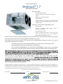
FIELD CONTROLS VentCool Whole House Fan Model 1.7 is designed to provide natural, quiet, and energy-efficient cooling for many years. It is a powerful fan that can exhaust hot air from your home and draw cool air from outside, helping to reduce your energy expense by eliminating or reducing the need for air conditioning. The fan is easy to install and operate, and it comes with a 50-foot CAT5 cable for convenient placement of the wall control. The VentCool Whole House Fan Model 1.7 is the perfect way to keep your home cool and comfortable all summer long.
Here are some of the features and benefits of the FIELD CONTROLS VentCool Whole House Fan Model 1.7:


-
 1
1
-
 2
2
-
 3
3
-
 4
4
-
 5
5
-
 6
6
-
 7
7
-
 8
8


FIELD CONTROLS VentCool Whole House Fan Model 1.7 Installation guide
- Type
- Installation guide
- This manual is also suitable for
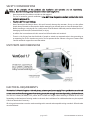
FIELD CONTROLS VentCool Whole House Fan Model 1.7 is designed to provide natural, quiet, and energy-efficient cooling for many years. It is a powerful fan that can exhaust hot air from your home and draw cool air from outside, helping to reduce your energy expense by eliminating or reducing the need for air conditioning. The fan is easy to install and operate, and it comes with a 50-foot CAT5 cable for convenient placement of the wall control. The VentCool Whole House Fan Model 1.7 is the perfect way to keep your home cool and comfortable all summer long.
Here are some of the features and benefits of the FIELD CONTROLS VentCool Whole House Fan Model 1.7:
Ask a question and I''ll find the answer in the document
Finding information in a document is now easier with AI
Related papers
-
FIELD CONTROLS VentCool Tahoe Series Whole House Fan Installation guide
-
-
-
-
-
-
-
-
-
Other documents
-
Gibraltar Building Products VD616G Operating instructions
-
 Battic Door Energy Conservation Products 22x54R-50 Installation guide
-
 Centric Air 3.4A Operating instructions
-
 Comfort Cool Fans QA-Deluxe 6500(R) Operating instructions
-
Air Vent EV16624BR User guide
-
 ARCTIC COOLING CX242DDWT User manual
-
Marley Engineered Products 2438 User manual
-
 Tamarack HV3400R50 Specification
-
 Air Vent PLSLBL Specification
-
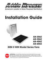 Attic Breeze AB–6062 Installation guide


