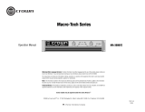
Crown XLS 202 Owner's manual

Type
Owner's manual
XLS 202
Operation Manual
Obtaining Other Language Versions: To obtain informa-
tion in another language about the use of this product, please
contact your local Crown Distributor. If you need assistance
locating your local distributor, please contact Crown at 574-
294-8000.
This manual does not include all of the details of design,
production, or variations of the equipment. Nor does it cover
every possible situation which may arise during installation,
operation or maintenance.
The information provided in this manual was deemed accurate
as of the publication date. However, updates to this information
may have occurred. To obtain the latest version of this manual,
please visit the Crown website at www.crownaudio.com.
Trademark Notice: Crown, Crown Audio, and Amcron are
registered trademarks of Crown International. Other trademarks
are the property of their respective owners.
Later versions of this manual and additional information about
this product may be available at the Crown website at www.
crownaudio.com.
Some models may be exported under the name
Amcron
®
©2008 by Crown Audio
®
, Inc., 1718 W. Mishawaka Rd.,
Elkhart, Indiana 46517-9439 U.S.A. Telephone: 574-294-8000.
139441-4
1/08
XLS 602
XLS 402
Weitere Sprachversionen: bitte wenden Sie sich an
Ihren zuständigen Crown-Vertrieb für eine Bedienung-
sanleitung in Ihrer Sprache. Telefonische Auskunft über
Ihren zuständigen Vertrieb erhalten Sie bei Crown unter
001-574-294-8000.
Diese Bedienungsanleitung enthält nicht sämtliche Einzel-
heiten der Konstruktion, Herstellung und Produktvarianten.
Sie berücksichtigt auch nicht alle möglichen Situationen,
die während der Installation, Bedienung und Wartung
auftreten können.
Die Informationen in dieser Bedienungsanleitung wurden
zum Zeitpunkt ihrer Veröffentlichung als korrekt erachtet.
Sie können jedoch mittlerweile auf einen neueren Stand ge-
bracht worden sein. Für die jeweils jüngste Version dieser
Bedienungsanleitung besuchen Sie bitte die Crown-Website
unter www.crownaudio.com.
Warenzeichen: Crown, Crown Audio und Amcron sind
eingetragene Warenzeichen von Crown International.
Andere Warenzeichen sind das Eigentum ihrer jeweiligen
Rechteinhaber.
Einige Modelle können unter dem Namen Amcron
®
vertrieben werden.
©2008 Crown Audio
®
Inc., 1718 W. Mishawaka Rd.,
Elkhart, Indiana 46517-9439 U.S.A., Tel. 001-574-294-
8000.
Pour Obteniendo otras Versiones de Idioma: Para
obtener información en otro idioma acerca del uso de este
producto, contacte por favor a su Distribuidor Crown local.
Si necesita asistencia para localizar a su distribuidor local,
favor de contactar a Crown al 574-294-8000.
Este manual no incluye todos los detalles de diseño,
producción, o variaciones del equipo. Tampoco cubre
cualquier posible situación que pueda surgir durante la
instalación, operación o mantenimiento.
La información provista en este manual fue considerada
precisa a la fecha de publicación. Sin embargo, pueden
haber ocurrido actualizaciones a esta información. Para
obtener la última versión de este manual, por favor visite la
página de internet de Crown en www.crownaudio.com.
Nota de Marcas Registradas: Crown, Crown Audio y
Amcron son marcas registradas de Crown International.
Otras marcas son de la propiedad de sus respectivos
dueños.
Algunos modelos pueden ser exportados bajo el
nombre de Amcron
®
.
Derechos reservados por Crown Audio
®
Inc, ©2008., 1718
W. Mishawaka Rd., Elkhart Indiana 46517-9439 U.S.A.,
XLS Series XLS
Gamme XLS Serie XLS
XLS 802
Bedienungsanleitung
Manual de Operación
XLS 5000
得到其他语言版本的方法:要获得关于此产品使用方
法的其他语言版本,请联系当地的皇冠品牌产品供应
商。如果需要帮助才能得知当地供应商的地址,请联
系皇冠公司服务号码574-294-8000。此说明书并不包
括产品的设计、生产和更新的所有详细信息,也不包
括在安装、使用和维护过程中可能遇到的所有问题。
此说明书的内容在出版之时是精确的,然而,之后的
产品可能会有升级,从而带来不符合说明书之处。要
获得最新版本的说明书,请访问皇冠的官方网站:
www.crownaudio.com.
商标说明:Crown, Crown Audio Amcron三个商标是
皇冠国际集团的注册商标,除此之外,其他商标归各
商标业主所有。
一些型号的产品可能以Amcron.®品牌的名义出口。
©2007 皇冠集团, 1718 W. Mishawaka Rd., Elkhart,
印第安那州 46517-9439 美国. 电话: 574-294-8000
Operation Manual
Leistungsendstufen Amplifi cadores de potencia
XLS Series Power Amplifi ers
Bedienungsanleitung Manual de Operación
1. Read these instructions.
2. Keep these instructions.
3. Heed all warnings.
4. Follow all instructions.
5. Do not use this apparatus near water.
6. Clean only with a dry cloth.
7. Do not block any ventilation openings. Install in accordance
with the manufacturer’s instructions.
8. Do not install near any heat sources such as radiators, heat
reg isters, stoves, or other apparatus (including amplifi ers)
that produce heat.
9. Do not defeat the safety purpose of the polarized or
grounding-type plug. A polarized plug has two blades with
one wider than the other. A grounding-type plug has two
blades and a third grounding prong. The wide blade or
the third prong is provided for your safety. If the provided
plug does not fi t into your outlet, consult an electrician for
replacement of the obsolete outlet.
Important Safety Instructions
MAGNETIC FIELD
CAUTION! Do not locate sensitive high-gain equipment such as
preamplifi ers or tape decks directly above or below the unit. Because
this amplifi er has a high power density, it has a strong magnetic fi eld
which can induce hum into unshielded devices that are located nearby.
The fi eld is strongest just above and below the unit.
If an equipment rack is used, we recommend locating the amplifi er(s)
in the bottom of the rack and the preamplifi er or other sensitive equip-
ment at the top.
The lightning bolt triangle is used to alert the user to the risk of
electric shock.
The exclamation point triangle is used to alert the user to
important operating or maintenance instructions.
REGARDEZ CES SYMBOLES:
La triangle avec le sigle ‘’foudre’’ est employée pour alerter
l’utilisateur au risque de décharge électrique. Le triangle avec
un point d’exclamation est employée pour alerter l’utilisateur
d’instruction importantes pour lors opérations de mainte nance.
ATENCION CON ESTOS SÍMBOLOS:
El triángulo con el símbolo de rayo eléctrico es usado para
alertar al usuario de el riesgo de un choque eléctrico.
El triángulo con el signo de admiración es usado para alertar
al usuario de instrucciones importantes de operación o man-
tenimiento.
WATCH FOR THESE SYMBOLS:
IMPORTANT
XLS Series amplifi ers require Class 2 output wiring.
Les amplifi cateurs de série de XLS exigent des câbles de sortie de
classe 2.
XLS-Reihe-Verstärker verlangen Klasse die 2 Produktionsverdrah tung.
Los amplifi cadores de la Serie XLS requieren de un cableado de sal ida
Clase 2.
TO PREVENT ELECTRIC SHOCK DO NOT REMOVE TOP OR
BOTTOM COVERS. NO USER SERVICEABLE PARTS INSIDE.
REFER SERVICING TO QUALIFIED SERVICE PERSONNEL.
À PRÉVENIR LE CHOC ÉLECTRIQUE N’ENLEVEZ PAS LES
COUVERCLES. IL N’Y A PAS DES PARTIES SERVICEABLE
À L’INTÉRIEUR. TOUS REPARATIONS DOIT ETRE FAIRE PAR
PERSONNEL QUALIFIÉ SEULMENT.
PARA PREVENIR UN CHOQUE ELÉCTRICO, NO RETIRE LAS
CUBIERTAS SUPERIOR O INFERIOR. NO EXISTEN PARTES QUE
PUEDAN SER REPARADAS POR EL USUARIO AL INTE RIOR.
REMITA EL SERVICICO AL PERSONAL TÉCHNICAL CALIFI-
CADO.
TO COMPLETELY DISCONNECT THIS EQUIPMENT FROM THE
AC MAINS, DISCONNECT THE POWER SUPPLY CORD PLUG
FROM THE AC RECEPTACLE. THE MAINS PLUG OF THE POWER
SUPPLY CORD SHALL REMAIN READILY OPERABLE.
POUR DÉMONTER COMPLÈTEMENT L’ÉQUIPEMENT DE
L’ALIMENTATION GÉNÉRALE, DÉMONTER LE CÂBLE D’ALI-
MENTATION DE SON RÉCEPTACLE. LA PRISE D’ALIMEN TATION
RESTERA AISÉMENT FONCTIONNELLE.
PARA DESCONECTAR COMPLETAMENTE EL EQUIPO DEL
SUMINSTRO ELECTRICO, DESCONECTE EL CABLE DE ALI-
MENTACION DE LA TOMA DE CA. LAS PATAS DEL CONEC TOR
DEL CABLE DE ALIMENTACIÓN DEBERAN MANTENERSE EN
BUEN ESTADO.
FCC COMPLIANCE NOTICE
This device complies with part 15 of the FCC rules. Operation is subject to the following
two conditions: (1) This device may not cause harmful interference, and (2) this device
must accept any interference received, including interference that may cause undesired
operation.
CAUTION: Changes or modifi cations not expressly approved by the party responsible for
complicance could void the user’s authority to operate the euqipment.
NOTE: This equipment has been tested and found to comply with the limits for a Class B
digital device, pursuant to part 15 of the FCC Rules. These limits are designed to provide
reasonable protection against harmful interference in a residential installation. This equip-
ment generates, uses, and can radiate radio frequency energy and, if not installed and used
in accordance with the instruction manual, may cause harmful interference to radio com-
munications. However, there is no guarantee that interference will not occur in a particular
installation. If this equipment does cause harmful interference to radio or television recep-
tion, which can be determined by turning the equipment off and on, the user is encouraged
to try to correct the interference by one or more of the following measures:
• Reorient or relocate the receiving antenna.
• Increase the separation between the equipment and receiver.
• Connect the equipment into an outlet on a circuit different from that to which the
receiver is connected.
• Consult the dealer or an experienced radio/TV technician for help.
10. Protect the power cord from being walked on or pinched,
par ticularly at plugs, convenience receptacles, and the point
where they exit from the apparatus.
11. Only use attachments/accessories specifi ed by the manufac-
turer.
12. Use only with a cart, stand, tripod, bracket, or table specifi ed
by the manufacturer, or sold with the apparatus. When a
cart is used, use caution when moving the cart/apparatus
combination to avoid injury from tip-over.
13. Unplug this apparatus during lightning storms or when
unused for long periods of time.
14. Refer all servicing to qualifi ed service personnel. Servicing
is required when the apparatus has been damaged in any
way, such as power-supply cord or plug is damaged, liquid
has been spilled or objects have fallen into the apparatus,
the apparatus has been exposed to rain or moisture, does
not operate nor mally, or has been dropped.
15. Use the mains plug to disconnect the apparatus from the
mains.
16. WARNING: TO REDUCE THE RISK OF FIRE OR ELECTRIC
SHOCK, DO NOT EXPOSE THIS APPARATUS TO RAIN OR
MOISTURE.
17. DO NOT EXPOSE THIS EQUIPMENT TO DRIPPING OR
SPASHING AND ENSURE THAT NO OBJECTS FILLED
WITH LIQUIDS, SUCH AS VASES, ARE PLACED ON THE
EQUIPMENT.
18. THE MAINS PLUG OF THE POWER SUPPLY CORD SHALL
REMAIN READILY OPERABLE.
Wichtige Sicherheitsinstruktionen
Instrucciones de Seguridad Importantes
Operation Manual
Leistungsendstufen Amplifi cadores de potencia
XLS Series Power Amplifi ers
Bedienungsanleitung Manual de Operación
Equipment Type: Power amplifi ers
Family Name: XLS Series
Model Names: XLS 202, XLS 402, XLS 602, XLS 802, XLS 5000
EMC Standards:
EN 55103-1:1995 Electromagnetic Compatibility - Product Family Standard for Audio, Video, Audio-Visual and Entertainment Lighting Control Apparatus for Professional Use, Part 1: Emissions
EN 55103-1:1995 Magnetic Field Emissions-Annex A @ 10 cm and 1 M
EN 61000-3-2:1995+A14:2000 Limits for Harmonic Current Emissions (equipment input current 16A per phase)
EN 61000-3-3:1995 Limitation of Voltage Fluctuations and Flicker in Low-Voltage Supply Systems Rated Current16A
EN 55022:1992 + A1: 1995 & A2:1997 Limits and Methods of Measurement of Radio Disturbance Characteristics of ITE: Radiated, Class B Limits; Conducted, Class B
EN 55103-2:1996 Electromagnetic Compatibility - Product Family Standard for Audio, Video, Audio-Visual and Entertainment Lighting Control Apparatus for Professional Use, Part 2: Immunity
EN 61000-4-2:1995 Electrostatic Discharge Immunity (Environment E2-Criteria B, 4k V Contact, 8k V Air Discharge)
EN 61000-4-3:1996 Radiated, Radio-Frequency, Electromagnetic Immunity (Environment E2, Criteria A)
EN 61000-4-4:1995 Electrical Fast Transient/Burst Immunity (Criteria B)
EN 61000-4-5:1995 Surge Immunity (Criteria B)
EN 61000-4-6:1996 Immunity to Conducted Disturbances Induced by Radio-Frequency Fields (Criteria A)
EN 61000-4-11:1994 Voltage Dips, Short Interruptions and Voltage Variation
Safety Standard:
EN 60065: 1998 Safety Requirements - Audio Video and Similar Electronic Apparatus
I certify that the product identifi ed above conforms to the requirements of the EMC Council Directive 89/336/EEC as amended by 92/31/EEC, and the Low Voltage Directive 73/23/EES as amended by 93/68/EEC.
DECLARATION OF CONFORMITY
Crown International, Inc.
Issued By: Crown International, Inc.
1718 W. Mishawaka Rd.
Elkhart, IN 46517 U.S.A.
Sue Whitfi eld
574-294-8289
European Representative’s Name and Address:
David J. Budge
10 Harvest Close
Yateley
GU46 6YS
United Kingdom
Date of Issue: January 1, 2008
Signed
Larry Coburn
Title: Senior Vice President of Manufacturing
TFOR COMPLIANCE QUESTIONS ONLY:
Leistungsendstufen Amplifi cadores de potencia
XLS Series Power Amplifi ers
Operation Manual Bedienungsanleitung Manual de Operación
Larry Coburn
发行: 皇冠国际集团
1718 W. Mishawaka
Elkhart, 印第安那州 46517 美国
欧洲代表的名字和地址
David J. Budge
10 Harvest Close
Yateley
GU46 6YS
United Kingdom
设备种类:商业声频功放
总类别名称:XLS 系列扩音器
型号:XLS 202, XLS 402, XLS 602, XLS 802
电磁兼容性标准:
EN 55103-1:1997 电磁兼容性---符合Product Family Standard for Audio, Video, Audio-Visual and Entertainment Lighting Control Apparatus for Professional Use 的第一部分(辐射部分)规
定的标准
EN 55103-1:1997 符合 Magnetic Field Emissions-附件 A @ 10 cm 20 cm 的标准
EN 61000-3-2:2001 符合Limits for Harmonic Current Emissions(设备输入电流小于或者等于每相位16安)规定的标准
EN 61000-3-3:2002 符合Limitation of Voltage Fluctuations and Flicker in Low-Voltage Supply Systems Rated Current(小于或者等于16安)规定的标准
EN 55022:2003 符合Limits and Methods of Measurement of Radio Disturbance Characteristics of ITE 中的辐射B级限定条件和传导A级限定条件
EN 55103-2:1997 符合Electromagnetic Compatibility - Product Family Standard for Audio, Video, Audio-Visual and Entertainment Lighting Control Apparatus for Professional Use 的第二部分
(免疫性部分)规定的标准
EN 61000-4-2:2001 符合 Electrostatic Discharge Immunity 规定的标准
EN 61000-4-3:2001 符合Radiated, Radio-Frequency, Electromagnetic Immunity (E2 环境下, A 标准)规定的标准
EN 61000-4-4:2001 符合Electrical Fast Transient/Burst Immunity (标准 B) 规定的标准
EN 61000-4-5:2001 符合Surge Immunity (标准B) 规定的标准
EN 61000-4-6:2003 符合 Immunity to Conducted Disturbances Induced by Radio-Frequency Fields (标准A) 规定的标准
EN 61000-4-11:2001 符合Voltage Dips, Short Interruptions and Voltage Variation 规定的标准
安全标准:
IEC 60065: 2001 7th Ed. 符合Safety Requirements - Audio Video and Similar Electronic Apparatus 规定的标准
我保证上述产品符合92/31/EEC 修正的EMC Council Directive 89/336/EEC 所规定的条件,也符合93/68/EEC 修正的Low Voltage Directive 73/23/EES 所规定的条件。
由于线电流和声的因素,我们建议在连接之前,你应该与你的供应商授权单位联系。 签署:
仅解决符合条款问题:
联系人:Sue Whitfi eld.
574-294-8289
头衔:负责制造的资深副总裁
日期:2005 12 12
皇冠国际集团
Operation Manual
Leistungsendstufen Amplifi cadores de potencia
XLS Series Power Amplifi ers
Bedienungsanleitung Manual de Operación
Table of Contents Inhalt Indice
Wichtige Sicherheitshinweise .................................2, 3
Herstellerbescheinigung .........................................4, 5
1 Einleitung .....................................7
1.1 Ausstattungsmerkmale .................................8
1.2 Zu dieser Bedienungsanleitung ....................8
2 Installation ....................................9
2.1 Auspacken der Endstufe ..............................9
2.2 Einbau der Endstufe ....................................10
2.3 Kühlung ......................................................10
2.4 Eingangsverbindungen ...............................11
2.5 Ausgangsverbindungen ..............................12
2.6 Verkabelung ................................................13
2.6.1 Stereo ..................................................13
2.6.2 Mono-Brückenbetrieb ..........................15
2.7 Netzanschluß ..............................................17
2.8 Lautsprecherschutz .....................................17
2.9 Inbetriebnahme ...........................................18
3 Bedienung .................................... 19
3.1 Vorsichtsmaßnahmen ..................................19
3.2 Vorderseitige Regler und Anzeigen ...............20
3.3 XLS 202, 402, 602, 802
Rückseitige Regler und Anschlüsse ...............21
3.4 XLS 5000
Rückseitige Regler und Anschlüsse ..............22
4 Fortgeschrittene Ausstattungsmerkmale und
Optionen ......................................... 23
4.1 Schutzschaltungen ......................................23
4.1.1 Ausgangsstrombegrenzung ..................23
4.1.2 Gleichstromschutz ...............................23
4.1.3 Unterbrecher ........................................24
4.1.4 Thermischer Schutz..............................24
5 Fehlersuche ................................... 25
6 Technische Daten ............................ 27
7 Wartung ........................................ 28
8 Garantie ....................................... 31
Anmeldeformular............................................35, 37
Crown Audio Factory Service Information Form....39, 41
Instrucciones de Seguridad Importantes.....................2, 3
Declaración de Conformidad......................................4, 5
1 Bienvenida ........................................7
1.1 Características ..................................................8
1.2 Como usar este manual.....................................8
2 Instalación ........................................9
2.1 Desempaque su Amplifi cador...........................9
2.2 Instale su amplifi cador ......................................10
2.3 Asegure una Ventilación Adecuada ...................10
2.4 Seleccione el Cableado y Conectores
de Entrada ..........................................................11
2.5 Seleccione el Cableado y Conectores
de Salid ..............................................................12
2.6 Cablee Su Sistema ............................................13
2.6.1 Modo Stereo .............................................13
2.6.2 Modo Bridge-Mono ..................................15
2.7 Conecte al suministro eléctrico .........................17
2.8 Protegiendo Sus Altavoces ...............................17
2.9 Procedimiento de Encendido ............................18
3 Operación .........................................19
3.1 Precauciones ....................................................19
3.2 Controles e Indicadores del Panel Frontal .........20
3.3 XLS 202, 402, 602, 802
Controles y conectores del Panel Trasero .........21
3.4 XLS 5000
Controles y conectores del Panel Trasero ........22
4 Opciones y Características Avanzadas ........23
4.1 Sistemas de Protección .....................................23
4.1.1 Limitación de la Corriente de Salida ..........23
4.1.2 Protección Contra Corriente Directa (DC) ..23
4.1.3 Interruptor Termo Magnético .....................24
4.1.4 Protección Térmica ...................................24
5 Solución de Problemas .........................25
6 Especifi caciones .................................27
7 Servicio ...........................................28
8 Garantía ...........................................31
Garantia de Registro..............................................35, 37
Crown Audio Factory Service Information Form.......39, 41
Important Safety Instructions ....................................2, 3
Declaration of Conformity .........................................4, 5
1 Welcome .........................................7
1.1 Features ...........................................................8
1.2 How to Use This Manual ..................................8
2 Setup .............................................9
2.1 Unpack Your Amplifi er ....................................9
2.2 Install Your Amplifi er......................................10
2.3 Ensure Proper Cooling ...................................10
2.4 Choose Input Wire and Connectors ................11
2.5 Choose Output Wire and Connectors .............12
2.6 Wire Your System...........................................13
2.6.1 Stereo Mode...........................................13
2.6.2 Bridge-Mono Mode................................15
2.7 Connect to AC Mains .....................................17
2.8 Protecting Your Speakers ...............................17
2.9 Startup Procedure ..........................................18
3 Operation ....................................... 19
3.1 Precautions ....................................................19
3.2 Front Panel Controls and Indicators ................20
3.3 XLS 202, 402, 602, Back Panel
Controls and Connectors ...............................21
3.4 XLS 5000 Back Panel Controls
and Connectors ...............................................22
4 Advanced Features and Options ............. 23
4.1 Protection Systems ........................................23
4.1.1 Output Current Limiting .........................23
4.1.2. DC Protection........................................23
4.1.3 Circuit Breaker .......................................24
4.1.4 Thermal Protection .................................24
5 Troubleshooting ................................ 25
6 Specifi cations .................................. 27
7 Service .......................................... 28
8 Warranty ........................................ 31
Warranty Registration .............................................35, 37
Crown Audio Factory Service Information Form ......39, 41
重要的安全说明..............................................2, 3
符合性声明......................................................4, 5
1 前言.................................................................7
1.1 特性..............................................................8
1.2 此手册的使用方法......................................8
2 安装.................................................................9
2.1 打开包装......................................................9
2.2 安装..............................................................10
2.3 确保适度低温..............................................10
2.4 选择接入线和连接器..................................11
2.5 选择输出线和连接器..................................12
2.6 系统连接......................................................13
2.6.1 立体声模式...............................................13
2.6.2 单声道桥接模式.......................................15
2.7 连接交流电主线..........................................17
2.8 保护喇叭......................................................17
2.9 启动程序. ....................................................18
3 操作.................................................................19
3.1 防范..............................................................19
3.2 前面板控制和指示器..................................20
3.3 XLS 202, 402, 602, 802
后面板控制和指示器........................................21
3.4 XLS 5000后面板控制和指示器..................
22
4 高级特性和选项............................................ 23
4.1 保护系统......................................................23
4.1.1 输出限流...................................................23
4.1.2. 直流电保护..............................................23
4.1.3 断路开关...................................................24
4.1.4 热防护.......................................................24
5 故障诊断.........................................................25
6 规格.................................................................27
7 服务.................................................................28
8 维护.................................................................31
保修注册.........................................................35, 37
皇冠服务信息表.............................................39, 41
Leistungsendstufen Amplifi cadores de potencia
XLS Series Power Amplifi ers
Operation Manual Bedienungsanleitung Manual de Operación
The XLS Series of power amplifi ers from Crown
represents a new era in affordable, quality power
amplifi cation. The line consists of fi ve models in
a uniform, rugged chassis, incorporating the best
of tried-and-true design principles and innovative
features.
Modern power amplifi ers are sophisticated pieces
of engineering capable of producing extremely
high power levels. They must be treated with
respect and correctly installed if they are to pro-
vide the many years of reliable service for which
they were designed.
In addition, XLS Series amplifi ers include a
number of features which require some explana-
tion before they can be used to their maximum
advantage.
Please take the time to study this manual so that
you can obtain the best possible service from your
amplifi er.
1 Welcome
Crown XLS-Endstufen repräsentieren eine
neue Epoche erschwinglicher, hochwertiger
Leistungsverstärkung. Die XLS-Reihe besteht
aus fünf Modellen mit bewährten, vorteilhaften
Konstruktionsprinzipien und innovativen Ausstat-
tungsmerkmalen in einem einheitlichen robusten
Gehäuse.
Moderne Leistungsendstufen sind technisch
ausgereifte, komplexe Konstruktionen, die können
extreme Pegel erzeugen können. Sie müssen
sorgfältig behandelt und korrekt installiert werden,
um ihren vorgesehen Dienst zuverlässig und über
Jahre hinaus zu verrichten.
Darüber hinaus bieten XLS-Endstufen einige Aus-
tattungsmerkmale, deren Vorzüge einer näheren
Erklärung bedürfen.
Bitte nehmen Sie sich Zeit, diese Bedienungsanlei-
tung zu studieren, um die Leistungsfähigkeit Ihrer
Endstufe optimal nutzen zu können.
La Serie XLS de amplifi cadores Crown representa
una nueva era en amplifi cación de potencia de
cali-dad y accesible. La línea consiste de cinco
modelos en un chasis robusto y uniforme, incor-
porando lo mejor de los principios de diseño de
uso comprobado, y características innovadoras.
Los amplifi cadores de potencia modernos son
piezas de ingeniería sofi sticadas capaces de
producir niveles de potencia extremadamente
altos. Deben ser tratados adecuadamente e
instalados correctamente si se desea que provean
los muchos años de servicio efi ciente para los que
fueron diseñados.
Además, los amplifi cadores de la Serie XLS
incluyen varias características que requieren de
explicación antes de que puedan ser usados con el
mayor provecho.
Por favor dedique tiempo al estudio de este
manual para que usted pueda obtener el mejor
servicio posible de su amplifi cador.
1
1 Einleitung
1 Bienvenida
来自皇冠的XLS 系列功放代表着性价比高的功
放新时代。包括四个型号,均采用坚固的全钢质
机壳,包含最值得信赖的设计和革新的特性。
现代的功放是复杂的工程产品,能够达到非常高
的功率水平。如果要它们提供多年的可靠的稳定
工作,我们必须慎重对待并且正确安装它们。
另外,XLS 系列功放的许多特性要得到最好的优
势效果的话,还需要一些前提说明。为了得到最
好的服务质量,请用一些时间来学习此手册。
Operation Manual
Leistungsendstufen Amplifi cadores de potencia
XLS Series Power Amplifi ers
Bedienungsanleitung Manual de Operación
1.1 Features
• Simple, reliable design incorporates many popular features.
• Housed in a rugged, all-steel 2U chassis (3U in the XLS
5000).
• Effi cient forced-air fans prevent excessive thermal buildup.
• Electronically balanced XLR inputs. Touch-proof binding post
and Speakon® outputs.
• Features precision detented level controls, power switch,
power LED, and six LEDs which indicate signal, clip, and fault
for each channel.
1.2 How to Use This Manual
This manual provides you with the necessary information to
safely and correctly setup and operate your amplifi er. It does
not cover every aspect of installation, setup or operation that
might occur under every condition. For additional information,
please consult Crown’s Amplifi er Application Guide (available
online at www.crownaudio.com), Crown Technical Support,
your system installer or retailer.
We strongly recommend you read all instructions, warnings and
cautions contained in this manual. Also, for your protection,
please send in your warranty registration card today. And save
your bill of sale — it’s your offi cial proof of purchase.
1.1 Ausstattungsmerkmale
• Zuverlässige Konstruktion mit umfangreicher Ausstattung
• Robustes 2HE-Stahlgehäuse (3HE in der XLS 5000)
• Wirksame Zwangskühlung verhindert Überhitzung
• Elektronisch symmetrierte XLR-Eingänge, berührungssichere
Schraubklemmen und Speakon®-Ausgänge
• Gerasterte Pegelsteller, Netzschalter, Power LED und sechs
LED-Anzeigen für Signal, Übersteuerung und Fehlerzustände
für jeden Kanal.
1.2 Zu dieser Bedienungsanleitung
Diese Bedienungsanleitung enthält alle nötigen Informationen
zur sicheren und korrekten Installation und Bedienung Ihrer
Endstufe. Sie deckt jedoch nicht alle Aspekte der Installation
und Bedienung ab, die unter sämtlichen möglichen Bedingun-
gen auftreten können. Für weitergehende Informationenen lesen
Sie bitte Crown’s Endstufen-Ratgeber (unter www.crownaudio.
com online erhältlich) oder wenden Sie sich an Ihren zuständi-
gen Vertrieb, Ihren Installateur oder Einzelhändler.
Wir empfehlen, diese Bedienungsanleitung und alle Sicherheit-
shinweise darin sorgfältig zu lesen. Senden Sie zu Ihrem Schutz
die Garantieregistration bitte umgehend ein. Und heben Sie Ihre
Quittung als offi ziellen Kaufbeleg auf!
1.1 Características
• El diseño simple y efi ciente incorpora muhas características
populares.
• Alojado en un chasis resistente de 2 Unidades, completa-
mente de acero (3 Unidades en el XLS 5000).
• Ventilador efi ciente de aire forzado que previene el calenta-
miento excesivo.
• Entradas XLR electrónicamente balanceadas. Salidas
de postes de conexión a prueba de contacto accidental y
Speakon®.
• Cuenta con controles de nivel dentados de precisión, inter-
ruptor de encendido, LED de encendido y seis LED que indican
señal, saturación (clip) y falla para cada canal.
1.2 Como usar este manual
Este manual le proporciona la información necesaria para
confi gurar y operar, segura y correctamente su amplifi cador.
No cubre todos los aspectos de la instalación, confi guración u
operación que pudieran ocurrir bajo todas las condiciones.
Para información adicional, favor de consultar La Guía de
Aplicación de Amplifi cadores de Crown (disponible en línea
en www.crownaudio.com) o, contactar al soporte técnico de
Crown, a su instalador del sistema o a su tienda local.
Le exhortamos a que lea todas las instrucciones, advertencias
y precauciones contenidas en este manual. También, para su
protección, envíenos su tarjeta de registro de garantía hoy
mismo. Conserve su nota de venta - es su comprobante de
compra ofi cial.
1 Welcome
1
1 Einleitung
1 Bienvenida
1.1 特性
简洁、可信赖的设计,有很多时尚的性能
采用坚固的全钢质2U 机壳
高效通风扇避免热量累积
电子平衡XLR 输入,防接触接线柱和专业
Speakon®输出端
特色是有精确控制、功率转换、功率LED
6 个显示每个声道的信号、削波和故障
的指示器
1.2 此手册的使用方法
此手册提供了安全、正确安装和操作功放
的必要信息。但它并没有涵盖一定情形下
的关于安装、设置和操作的方方面面。要
获得更多信息,请参阅《皇冠功放指南》
(在线查阅网址www.crownaudio.com)和
《皇冠技术支持》,咨询你的安装者或者
销售商。
我们强烈建议你阅读手册全部说明、警告
和提示。另外,为了保护你的权益,请现
在发送你的保修注册卡给我们。保留你的
单据,那是你的购买凭证。。
Leistungsendstufen Amplifi cadores de potencia
XLS Series Power Amplifi ers
Operation Manual Bedienungsanleitung Manual de Operación
2 Setup
2.1 Unpack Your Amplifi er
Please unpack and inspect your amplifi er for any damage
that may have occurred during transit. If damage is
found, notify the transportation company immediately.
Only you can initiate a claim for shipping damage. Crown
will be happy to help as needed. Save the shipping car-
ton as evidence of damage for the shipper’s inspection.
We also recommend that you save all packing materials
so you will have them if you ever need to transport the
unit. Never ship the unit without the factory pack.
YOU WILL NEED (not supplied):
• Input wiring cables
• Output wiring cables
• Rack for mounting amplifi er (or a stable surface for
stacking)
WARNING: Before you start to set up your
amplifi er, make sure you read and observe the
Important Safety Instructions found at the begin-
ning of this manual.
2.1 Auspacken der Endstufe
Bitte untersuchen Sie Ihre Endstufe nach dem Auspacken
auf mögliche Transportschäden. Benachrichtigen Sie den
Transporteur im Falle eines Schadens umgehend, denn
nur Sie können den Schaden geltend machen. Falls nötig
wird Crown Sie dabei unterstützen. Bewahren Sie den
Versandkarton zum Schadensbeweis auf.
Wir empfehlen auch, das Verpackungsmaterial zum
eventuellen Transport des Geräts aufzubewahren. Bitte ver-
schicken Sie das Gerät immer in der Originalverpackung.
SIE BENÖTIGEN (im Lieferumfang nicht enthalten):
• Lautsprecherkabel
• ein Rack zum Einbau der Endstufe (oder eine stabile
Oberfl äche zum Stapeln)
WARNUNG: Befolgen Sie in jedem Fall die
wichtigen Sicherheitshinweise am Anfang dieser
Bedienungsanleitung, bevor Sie mit der Installa-
tion Ihrer Endstufe beginnen!
2.1 Desempaque Su Amplifi cador
Por favor desempaque e inspeccione su amplifi cador por
cualquier daño que pueda haber ocurrido durante el trans-
porte. Si encuentra algún daño, notifi que inmediatamente
a la compañía transportista. Solamente usted podrá iniciar
una reclamación por daños durante el envío. Crown se
complacerá en brindar la ayuda necesaria. Conserve el
empaque de envío como prueba del daño para la inspec-
ción del remitente.
También le recomendamos conservar todos los materiales
de empaque para que cuente con ellos en caso de
necesitar transportar la unidad. Nunca envíe la unidad sin
el empaque de fábrica.
USTED NECESITARA (No provisto):
• Cables para la conexión de entrada
• Cables para la conexión de salida
• Gabinete para montar el amplifi cador (o una superfi cie
estable para ponerlo encima)
ADVERTENCIA: Antes de empezar a confi gurar el
amplifi cador, asegúrese de leer y observar las
Instrucciones de Seguridad Importantes que se
encuentran al principio de este manual.
2
2 Installation
2 Instalación
2.1 打开包装
打开包装并检查你的功放有无损坏,在运输
过程中可能引起损坏。如果有损坏,立即通
知运输公司。只有你本人可以对运输造成的
损坏进行申诉,不过皇冠很乐意提供所需的
帮助。保留外包装箱作为损坏的证据,拿给
运输人员检查。
我们还建议你保留所有的包装材料,当你想
再次运输设备时可以再次利用它们。不要
在没有厂家包装的情况下运输。
你需要(未提供):
输入缆线
输出缆线
安装架(或者稳固的放置平台)
警告:当你开始设置你的功放时,确保你
已经阅读并遵守此手册开始部分所讲的重
要安全说明。
Operation Manual
Leistungsendstufen Amplifi cadores de potencia
XLS Series Power Amplifi ers
Bedienungsanleitung Manual de Operación
2.2 Install Your Amplifi er
CAUTION: Before you begin, make sure your amplifi er
is disconnected from the power source, with the power
switch in the “off” position and all level controls turned
completely down (counterclockwise).
Use a standard 19-inch (48.3 cm) equipment rack (EIA
RS-310B). See Figure 2.1 for amplifi er dimensions.
NOTE: When transporting, amplifi ers should be supported
at both front and back.
2.3 Ensure Proper Cooling
For optimum cooling, rack Crown amps without spaces be-
tween them. If amps are racked with spaces between them,
solid non-vented rack panels are recommended between
amps. Crown K series, D series, and CCA convection-
cooled amps are the exception: they require at least one
rack space (1.75 inches) of open or vented panel space
between amplifi ers.
DO NOT block front or rear air vents. The side walls of the
rack should be a minimum of two inches (5.1 cm) away
from the amplifi er sides, and the back of the rack should
be open.
Figure 2.2 illustrates standard amplifi er airfl ow.
.
Figure 2.1
Dimensions
Figure 2.2
Airfl ow
2 Setup
2.2 Einbau der Endstufe
ACHTUNG: Vergewissern Sie sich vor dem Einbau, daß
Ihre Endstufe vom Netz getrennt ist, der Netzschalter in der
“OFF”-Position steht und alle Pegelsteller auf Linksan-
schlag stehen.
Verwenden Sie ein Standard 19”-Rack (48,3 cm; EIA
RS-310B). siehe Abbildung 2.1 Zu den Endstufenabmes-
sungen siehe Abbildung 2.1.
ACHTUNG: Zum Transport sollte die Endstufe an Vorder-
und Rückseite abgestützt sein.
2.3 Kühlung
Im rack: kein Abstand zwischen Verstärkern. Oder keine
gelüfteten rack Platten zwischen Verstärkern.
Blockieren Sie UNTER KEINEN UMSTÄNDEN die
Belüftungsöffnungen. Die Seitenwände des Racks sollten
mindestens 5cm Abstand zu den Seiten der Endstufe, die
Rückseite der Zahnstange sollte geöffnet sein.
Abbildung 2.2 zeigt den Luftstrom der Endstufe..
.
2.2 Instale Su Amplifi cador
PRECAUCION: Antes de empezar, asegúrese que su ampli-
cador esté desconectado del suministro eléctrico, con el
interruptor de encendido en la posición de “off “ (apagado)
y todos los controles de nivel completamente cerrados (en
dirección contraria a las manecillas del reloj).
Use un gabinete estándar para equipo (EIA RS-310B) de
19 pulgadas (48.3cm). Véase fi gura 2.1 para las dimensio-
nes del amplifi cador.
NOTA: Durante la transportación, los amplifi cadores de-
berán estar soportados tanto por el frente como por detrás.
2.3 Asegure una Ventilación Adecuada
En el rack, ningún espacio entre los amplifi cadores. O
paneles no ventilados entre los amplifi cadores.
NO bloquee la ventilación delantera o trasera. Las paredes
laterales del gabinete deberán estar separadas de los
costados de los amplifi cadores por lo menos dos pulgadas
(5.1cm), y a parte posteriora del gabinete debe estar
abierta.
La fi gura 2.2 ilustra el fl ujo de aire normal del amplifi ca-
dor.
.
2 2 Installation 2 Instalación
Abb. 2.1
Abmessungen
Figura 2.1
Dimensiones
Figure 2.2
Luftstrom
Figure 2.2
Flujo de Aire
2.1
尺寸
2.2 气流
2.2 安装功放
警告:安装前,确保功放断开电源,电源开
关在OFF位置,并且所有的控制都旋转到
最低值(逆时针方向旋转)
使用19 (48.3 cm) 标准设备架(EIA
RS-310B),见图2.1 功放尺寸
注意:在运输时,功放前后都需要垫撑。
2.3 确保适度低温
为了获得最理想的降温,架设皇冠功放时不
要留空隙,如果有空隙,则需要加塞不透风
的支架插板。
皇冠K 系列.D 系列和CCA 传送降温功放是例
外情况:它们需要至少一个开放的.通风的支
架空间(1.75 英寸)
不要阻碍前后气孔,支架的侧面板与功放之
间最少要有2 英寸(5.1 cm)的距离,并且支
架的后侧应该是开放的。
2.2 标准的功放气流
Leistungsendstufen Amplifi cadores de potencia
XLS Series Power Amplifi ers
Operation Manual Bedienungsanleitung Manual de Operación
2.4 Choose Input Wire and Con-
nectors
Crown recommends using pre-built or profes-
sionally wired, balanced line (two-conductor
plus shield), 22-24 gauge cables and connec-
tors. Use 3-pin male XLR connectors.
Unbalanced line may also be used but may
result in noise over long cable runs.
Figure 2.3 shows connector pin assignments
for balanced analog wiring. Figure 2.4 shows
connector pin assignments for unbalanced
analog wiring.
NOTE: Custom wiring should only be
performed by qualifi ed personnel.
Figure 2.3 Balanced Analog Input Connector Wiring
Figure 2.4 Unbalanced Analog Input Connector Wiring
2 Setup
2.4 Eingangsverbindungen
Crown empfi ehlt symmetrischen Anschluß
(zwei Leiter mit Schirm) über vorgefertigte
oder professionell verdrahtete Kabel mit einem
Leiterquerschnitt von 0,2 - 0,35mm² und einem
3-poligen männlichen XLR-Eingangsverbinder.
Unsymmetrischer Anschluß ist ebenfalls
möglich, kann aber bei langen Kabelwegen
Störpegel verursachen.
Abbildung 2.3 zeigt die Steckerbelegung für
symmetrischen, Abbildung 2.4 für unsymme-
trischen Anschluß.
ACHTUNG: Verwenden Sie nur hochwer-
tige, professionell verdrahtete Kabel.
2.4 Seleccione el Cableado y Co-
nectores de Entrada
Crown recomienda el uso de líneas balanceadas
( dos conductores más blindaje) prefabricadas
o profesionalmente construidas con cables
calibre 22 a 24 y conectores. Se le sugiere usar
conectores XLR machos de 3 terminales para
las entradas del amplifi cador. También se pu-
eden usar líneas desbalanceadas pero podrían
generar ruido en tramos largos de cable.
La fi gura 2.3 muestra las asignaciones de
las terminales del conector para un cableado
balanceado, y la fi gura 2.4 muestra las asigna-
ciones de las terminales del conector para un
cableado desbalanceado.
NOTA: El cableado especial deberá
ser realizado solamente por personal
califi cado.
2
2 Installation
2 Instalación
Abb. 2.3 Symmetrischer Anschluß
Figura 2.3 Cableado Balanceado del Conector de Entrada
Abb. 2.4 Unsymmetrischer Anschluß
Figura 2.4 Cableado Desbalanceado del Conector de Entrada
2.3 平衡输入连接器配线
2.4 不平衡输入连接器配线
2.4 选择输入线和接线器
皇冠建议使用预设的或者专业连接的平衡线(双导
体外加屏蔽),22-24 规格电缆线和连接器。你应
该使用三针XLR 电线接头连接至功放输入口。不平
衡线可能也会被使用,可是可能会对长距离传输带
来噪音。
2.3 显示平衡配线的连接头配置情况,图2.4
示不平衡配线的连接头配置情况。
注意:只有熟练的人才能根据习惯进行连接。
Operation Manual
Leistungsendstufen Amplifi cadores de potencia
XLS Series Power Amplifi ers
Bedienungsanleitung Manual de Operación
2.5 Choose Output Wire and Connectors
Crown recommends using pre-built or professionally
wired, high-quality, two- or four-conductor, heavy gauge
speaker wire and connectors. Use Class 1 output wiring.
You may use a 4-pole Speakon
®
connector (Figure 2.5)
or banana plugs, spade lugs, or bare wire for your output
connectors (Figure 2.6). To prevent the possibility of short-
circuits, wrap or otherwise insulate exposed loudspeaker
cable connectors.
Note: Binding post outputs on European models
come with safety plugs installed to prevent Euro-
pean power-cord plugs from being inserted. The
side entry positions for these connectors should
therefore be used with European models.
CAUTION – SHOCK HAZARD: Potentially lethal
voltages exist at the output connectors when the
amplifi er is turned on and is passing a signal.
Using the guidelines below, select the appropriate size of
wire based on the distance from amplifi er to speaker.
Distance Wire Size
up to 25 ft. 16 AWG
26-40 ft. 14 AWG
41-60 ft. 12 AWG
61-100 ft. 10 AWG
101-150 ft. 8 AWG
151-250 ft. 6 AWG
CAUTION: Never use shielded cable for output
wiring.
Figure 2.5 Top Speakon
®
Output Connector on
Back Panel
Bottom: Speakon
®
Cable Connector
Figure 2.6 Binding Post
Connections
2 Setup
2.5 Ausgangsverbindungen
Crown empfi ehlt vorgefertigte oder professionell ver-
drahtete hochwertige Lautsprecherkabel mit zwei oder vier
Leitern. Sie können 2- oder 4-polige Speakon
®
-Verbinder
(Abbildung 2.5 ), MDP-Stecker, oder blankes Kabel zum
Anschluß an die Ausgänge verwenden (Abbildung 2.6).
Isolieren Sie blankes Lautsprecherkabel zur Vermeidung
von Kurzschlüssen.
ACHTUNG: Um den versehentlichen Anschluß von
IEC-Netzkabeln zu verhindern, sind die Schraub-
klemmenausgänge der europäischen Modelle mit
Sicherheitskappen ausgestattet. Daher sollten bei
ihnen nur die oberen oder unteren Eingangsöff-
nungen dieser Anschlüsse verwendet werden.
CAUTION – SHOCK HAZARD: Potentially lethal
voltages exist at the output connectors when the
amplifi er is turned on and is passing a signal.
Wählen Sie die korrekte Leiterstärke entsprechend der
Distanz zwischen Endstufe und Lautsprecher:
Kabellänge Leiterquerschnitt
bis 7,5m 1,5mm²
7,5 - 12 m. 2mm²
12 - 18 m 3,5mm²
18 - 30 m 5mm²
30 - 45 m 8,5mm²
45 - 75 m 13mm²
VORSICHT: Verwenden Sie nie abgeschirmte
Kabel zum Lautsprecheranschluß.
2.5 Seleccione el Cableado y Conectores de
Salida
Crown recomienda el uso de conectores y cables de alta cali-
dad para altoparlantes, de dos conductores, de calibre grueso,
ya sean prefabricados o construidos profesionalmente. Usted
puede usar conectores Speakon
®
de 2 ó 4 polos (Figura 2.5),
conectores tipo Banana, ó cable desnudo para la conexión
de salida (Figura 2.6). Para prevenir la posibilidad de corto
circuito, cubra o de otra forma, aísle los conectores expuestos
del cable para altoparlante.
Nota: Los postes de conexión de salida en mod-
elos Europeos cuentan con tapones de seguridad
instalados para prevenir que sean insertados los
conectores Europeos de suministro eléctrico. Por lo
tanto, deberán ser usadas las posiciones de entrada
superior e inferior de estos conectores en los mod-
elos Europeos.
CAUTION – SHOCK HAZARD: Potentially lethal voltag-
es exist at the output connectors when the amplifi er
is turned on and is passing a signal.
Usando las referencias siguientes, seleccione el calibre
apropiado del cable basado en la distancia del amplifi cador al
altoparlante.
Distancia Calibre del Cable
Hasta 25 pies 16 AWG
26-40 pies 14 AWG
41-60 pies 12 AWG
61-100 pies 10 AWG
101-150 pies 8 AWG
151-250 pies 6 AWG
PRECAUCION: Nunca use cable blindado para el
cableado de salida.
2
2 Installation 2 Instalación
Figure 2.5 Oben: Speakon
®
-Ausgang auf der
Rückseite
Unten: Speakon
®
-Stecker
Figure 2.6 Anschluß an
Schraubklemmen, Stereo
Figure 2.6 Cableado de los
Postes de Conexión de
Salida para Modelos de 2
Canales
Figure 2.5Superior: Uno
de los Dos Conectores
Speakon
®
de Salida en el
Panel Trasero.
Inferior: Conector Speakon
®
para Cable
顶部:专业Speakon®输出端之一
后面板的连接器
底部:Speakon®电缆连接器
2.5
适合双路模式的接线
柱输出配线
2.6
2.5 选择输出线和连接器
皇冠建议使用预设的或者专业连接的.高品质的.
双导体的.粗铜丝连接线和连接器,你可以为你的
输出连接器选择双极或者四极Speakon®连接器
(图2.6.香蕉插头.或者接线柱(图2.5)。为
了避免短路,包裹或者使暴露的缆线连接器绝
缘。
注意:欧洲型号产品的接线柱附带有安全插头,
避免电源线插头被接入。这些连接器的侧面插入
点应该与欧洲型号产品同时使用。
使用下面指南,根据扩音器与喇叭的距离选择合
适的音箱。
警告:禁止使用屏蔽线作为输出配线。
距离 线的尺寸
25英尺以下. 16 AWG
25-40 英尺 14 AWG
41-60英尺 12 AWG
61-100英尺 10 AWG
101-150 英尺 8 AWG
151-250 英尺 6 AWG
Leistungsendstufen Amplifi cadores de potencia
XLS Series Power Amplifi ers
Operation Manual Bedienungsanleitung Manual de Operación
2.6 Wire Your System
2.6.1 Stereo Mode
Typical input and output wiring is shown in
Figure 2.7.
INPUTS: Connect input wiring for both channels.
OUTPUTS: Maintain proper polarity (+/–) on output
connectors.
Connect Channel 1 loudspeaker’s positive (+) lead
to Channel 1 positive (red) terminal of amp; repeat
for negative (–). Repeat Channel 2 wiring as for
Channel 1.
Figure 2.7 shows how to wire stereo speakers to the
binding posts.
Figure 2.7 System Wiring,
Stereo Mode, Using the
Binding Piosts
2 Setup
2.6 Verkabelung
2.6.1 Stereo
Abbildung 2.7 zeigt die typische Ein- und Ausgangs-
verkabelung.
EINGÄNGE: Schließen Sie die Kabel der beiden
Eingangskanäle an.
AUSGÄNGE: Achten Sie unbedingt auf korrekte Polar-
ität (+/-) der Anschlüsse.
Verbinden Sie den positiven Leiter (+) eines Laut-
sprecherkabels mit dem positiven Ausgang (rot) von
Kanal 1 der Endstufe und den negativen (-) mit dem
negativen Ausgang (schwarz). Schließen Sie das
zweite Lautsprecherkabel an Kanal 2 ebenso an.
Abbildung 2.7 zeigt den Lautsprecheranschluß an die
Vierfach-Schraubklemmen.
2.6 Cablee Su Sistema
2.6.1 Modo Stereo
El cableado típico de entrada y salida es mostrado en la
Figura 2.7
ENTRADAS: Conecte los cables de entrada para ambos
canales.
SALIDAS: Mantenga la polaridad adecuada (+/-) en los
conectores de salida.
Conecte el cable positivo(+) de el altoparlante del
Canal 1 a la terminal positiva (roja) del canal 1 del am-
plifi cador; repita para el negativo (-). Repita el proceso
completo del Canal 1 para el Canal 2.
La Figura 2.7 muestra como cablear altoparlantes en
Stereo a los postes de salida de conexión múltiple.
2
2 Installation
2 Instalación
XLS 202, 402, 602, 802
XLS 5000
Abb. 2.7 Stereo-Verkabelung
an den Fünfweg-Schraubklem-
men
Figura 2.7 Cableado del
Sistema, Modo Stereo
Usando los Postes de
Conexión Múltiple
声道1
喇叭
声道2
喇叭
声道1
喇叭
声道2
喇叭
2.7 系统配线
使用5 道的立体声模式
接线柱
2.6 系统连接
2.6.1 立体声模式
在图2.7 中显示了典型输入输出线的连接方式。
输入:两个通路都连接输入线
输出:保持输出连接器正负极正确
连接通路1 喇叭的正极至功放的正极(红色);
连接通路1 喇叭的负极(黑色);至功放的负极;
通路2 连接与通路1 相同。
2.7 显示怎样连接立体声喇叭与连接柱。
混音器 混音器
Operation Manual
Leistungsendstufen Amplifi cadores de potencia
XLS Series Power Amplifi ers
Bedienungsanleitung Manual de Operación
To wire stereo speakers to the Speakon
®
con-
nectors, use one of these methods:
Method 1 (Table 1 and Figure 2.8): Wire one
Speakon
®
cable connector to two speakers.
Insert the Speakon
®
cable connector into the
amplifi er’s top Speakon connector.
Method 2 (Table 2 and Figure 2.9): Plug the
Channel 1 speaker into the Channel 1 (top)
Speakon
®
connector, and plug the Channel 2
speaker into the Channel 2 (bottom) Speakon
®
connector.
Channel 1
Loudspeaker
Enceinte du
Canal 1
Lautsprecher
Kanal 1
Altoparlante
del Canal 1
Channel 2
Loudspeaker
Enceinte du
Canal 2
Lautsprecher
Kanal 2
Altoparlante
del Canal 2
Figure 2.8 Stereo Wiring Method 1: Wire Two Speakers to the Top Speakon
®
Connector
Figure 2.9 Stereo Wiring Method 2: Connect Each Speaker to a Different
Speakon
®
Connector
Channel 1
Loudspeaker
Channel 2
Loudspeaker
Speakon
(Channel 1)
Speakon
(Channel 2)
Enceinte du
Canal 1
Enceinte du
Canal 2
Speakon
(Canal 1)
Speakon
(Canal 2)
Speakon
(Kanal 1)
Lautsprecher
Kanal 1
Speakon
(Kanal 2)
Lautsprecher
Kanal 2
Altoparlante
del Canal 1
Altoparlante
del Canal 2
Speakon
(Canal 2)
C
hannel 1
L
ouds
p
eake
r
E
nceinte du
C
anal
1
L
auts
p
reche
r
Ka
n
al
1
Al
topar
l
ante
d
el
C
anal 1
C
hannel 2
L
ouds
p
eaker
nce
nte
u
C
anal
2
L
autsprecher
K
anal 2
Al
topar
l
ante
del
C
anal 2
Speakon
(Canal 1)
S
peakon
(
Channel 1
)
S
peakon
(
Canal 1
)
S
peakon
(
Kanal 1
)
S
p
eakon
(
C
anal 1
)
Stereo Wiring Method 1: Use Top Speakon
®
Only
Stereo Wiring Method 2: Use Both Speakons
®
PIN,Terminal
1+ 1– 2+ 2–
CH, Canal, Kanal
1+ 1– 2+ 2–
PIN,Terminal
销钉 终端
1+ 1–
CH, Canal, Kanal
通路
1+ 1–
PIN,Terminal
销钉 终端
1+ 1–
CH, Canal, Kanal
通路
2+ 2–
2 Setup
Zum Anschluß an die Speakon
®
-Buchsen
haben Sie zwei Möglichkeiten:
Methode 1 (Tabelle 1 und Abbildung 2.8): Ver-
drahten Sie einen Speakon
®
-Stecker mit den
Kabeln der beiden Lautsprecher und verbinden
Sie ihn mit der oberen Speakon
®
-Ausgang
Ihrer Endstufe.
Methode 2 (Tabelle 2 und Abbildung 2.9):
Verbinden Sie Lautsprecher 1 mit der oberen
(Kanal 1) und Lautsprecher 2 mit der unteren
Speakon
®
-Buchse ihrer Endstufe (Kanal 2).
Para cablear altoparlantes en Stereo a los co-
nectores Speakon
®
, use uno de estos métodos:
Método1 (Tabla 1 y Figura 2.8): Cablee un
conector Speakon
®
de cable a dos altoparlan-
tes. Inserte el conector Speakon
®
de cable en el
conector Speakon
®
superior del amplifi cador.
Método 2 (Tabla 2 Figura 2.9): Conecte el al-
toparlante 1 en el conector Speakon
®
del Canal
1 (superior), y conecte el altoparlante 2 en el
conector Speakon
®
del Canal 2 (inferior).
2 2 Installation 2 Instalación
Abb. 2.9 Stereo-Anschluß, Methode 2:
Verkabelung von zwei Lautsprechern mit individuellen Speakon
®
-Buchsen
Figura 2.9 Método 2 para el Cableado en Stereo. Conectar Cada
Altoparlante a Un Conector Speakon
®
Diferente
Stereo-Anschluß an der oberen Speakon
®
Método 1 para el Cableado en Stereo: Use Solamente el
Conector Speakon
®
Superior
Table 1
Tabelle 1
Tabla 1
Table 2
Stereo-Anschluß, Methode 2: Verkabelung von zwei
Lautsprechern mit individuellen Speakon
®
-Buchsen
Método 2 para el Cableado en Stereo: Use
ambos Conectores Speakon
®
Tabelle 2 Tabla 2
Abb. 2.8 Stereo-Anschluß, Methode 1: Verkabelung von zwei Lautsprechern mit der oberen
Speakon
®
-Buchse
Figura 2.8 Método 1 para el Cableado en Stereo: Cablear Dos Altoparlantes al Conector Speakon
®
2.8 立体声配线方法1:连接两个喇叭至 顶部Speakon®连接器
2.9 立体声配线方法2:连接每个喇叭至不同的 Speakon®连接器
1
2
立体声配线方法1:仅使用顶部Speakon®
立体声配线方法2:使用两个Speakons®
通路1
喇叭
顶部Speakon
底部
通路2
喇叭
要连接立体声喇叭至Speakon®连接器,使用如下方
法:
方法1(表1 和图28):连接一个Speakon®缆线
连接器至两个喇叭。把Speakon®缆线连接器嵌入功
放顶部的Speakon®连接器
方法2(表2 和图29):把通路1 喇叭插接到通
1(顶部)Speakon®连接器,并且把通路2 喇叭
插接到通路2(底部)Speakon®连接器
Leistungsendstufen Amplifi cadores de potencia
XLS Series Power Amplifi ers
Operation Manual Bedienungsanleitung Manual de Operación
2.6.2 Bridge-Mono Mode
Make sure the amplifi er is turned off and the
level controls are turned down before you wire
the system.
Typical input and output wiring is shown in
Figure 2.10.
INPUTS: Connect input wiring to CH 1.
OUTPUTS: Connect the speaker across the
positive (+) output terminals. Do not use the
negative (-) terminals when the amplifi er is
being operated in Bridge-Mono mode. Refer to
Section 2.5 for output connector pin assign-
ments. Make sure the Mode switch is set
to the “Bridge” position when operating
in Bridge-Mono mode.
Figure 2.10 Bridge-Mono Wiring
of 5-Way Binding Posts
2 Setup
2.6.2 Mono-Brückenbetrieb
Vergewissern Sie sich, dass die Endstufe aus-
geschaltet ist und die Pegelsteller der Endstufen
zurückgeregelt sind, bevor Sie das System
anschließen.
Abbildung 2.10 zeigt einen typischen Anschluß
EINGÄNGE: Schließen Sie die Kabel der beiden
Eingangskanäle an CH 1 an.
AUSGÄNGE: Schließen Sie den Lautsprecher an
die positiven (+) Ausgangsklemmen an. Benutzen
Sie nicht die negativen (-) Klemmen, wenn die
Endstufe im Mono-Brückenbetrieb läuft. Lesen
Sie Absatz 2.5 für weitere Informationen zur
Ausgangssteckerbelegung. Vergewissern Sie
sich, dass der Modus-Schalter auf der Po-
sition “Brücke” steht, um die Endstufe im
Mono-Brückenbetrieb laufen zu lassen.
2.6.2 Modo Bridge-Mono
Asegúrese de que el amplifi cador esté apagado
y los controles de nivel estén bajos antes de
conectar el sistema.
La Figura 2.10 muestra el cableado de entrada y
salida típico.
ENTRADAS: Conecte el cableado de entrada a
CH 1.
SALIDAS: Conecte el altoparlante a las termina-
les positivas (+) de salida. No utilice las termi-
nales negativas (-) cuando el amplifi cador esté
funcionando en Modo Bridge-Mono. Consulte
la Sección 2.5 acerca de las asignaciones de las
terminales del conector de salida. Asegúrese
de que el interruptor de Modo esté en la
posición “Bridge” cuando funcione en
modo Bridge-Mono.
2 2 Installation 2 Instalación
Abb. 2.10 Mono-Brückenbetrieb,
Schraubklemmen-Anschluß
Figura 2.10 Cableado en
Bridge-Mono de los Postes
de Conexión Múltiple
XLS 202, 402, 602, 802
XLS 5000
混音器
混音器
2.10 5 路接线柱的单声道桥接模式
配线
通路1
通路1
喇叭
喇叭
2.6.2 单声道桥接模式
在连接系统前,要确保断开电源,并且各
音量控制器调至最低。如图2.10 所示为典
型的输入和输出配线
输出:通过功放两个声道输出正极端子来
连接推动喇叭。当功放设为单声道桥接模
式工作时,请不要使用功放输出负极端
子。
参照2.5 部分布置输出接线插脚。当设
在单
声道桥接模式下操作时,确保模式开关设
定在"Bridge"位置上。
Operation Manual
Leistungsendstufen Amplifi cadores de potencia
XLS Series Power Amplifi ers
Bedienungsanleitung Manual de Operación
Figure 2.11 Alternate Bridge-Mono Wir-
ing: Loudspeaker Wired to Amplifi er’s Top
Speakon
®
Connector
2 Setup
2 2 Installation 2 Instalación
Top Speakon
®
Wiring for Bridge-Mono
PIN,Terminal
1+ 2+
CH, Canal, Kanal
通路
1+ 1–
Table 3
Mono-Brückenbetrieb an der oberen Speakon
®
Cableado en Bridge-Mono: Speakon
®
Superior del
Amplifi cador
Tabelle 3 Tabla 3
Abb. 2.11 Alternativer Mono-Brückenbe-
trieb: Lautsprecher-Anschluß an der oberen
Speakon
®
-Buchse
Figura 2.11 Cableado Alterno en Bridge-
Mono: Altoparlante Cableado al Conector
Speakonv
®
Superior del Amplifi cador
OUTPUTS: There are two ways to wire the amplifi er
output connectors for Bridge-Mono mode:
1) Wire the speaker across the red binding post of
each channel (Figure 2.10). Do not use the black
binding posts when the amp is being operated in
Bridge-Mono mode.
2) Wire the speaker only to the top Speakon® con-
nector as shown in Table 3 and Figure 2.11.
NOTE: Turn down (full CCW) the Channel 2
level control when operating the channel
pair in Bridge-Mono mode, as the Channel 1
level control works both channels.
NOTE: Crown provides a reference of wiring pin
assignments for commonly used connector types in
the Crown Amplifi er Application Guide available at
www.crownaudio.com.
AUSGÄNGE: Die Ausgänge der Endstufe können
zum Mono-Brückenbetrieb auf zwei Arten genutzt
werden:
1) Schließen Sie den Lautsprecher an die roten
Schraubklemmen von Kanal 1 und 2 an (Abbildung
2.10). Benutzen Sie im Mono-Brückenbetrieb
keinesfalls die schwarzen Schraubklemmen.
2) Schließen Sie den Lautsprecher nur an den
oberen Speakon®-Ausgang an (siehe Tabelle 3 und
Abbildung 2.11).
ACHTUNG: Regeln Sie (voll CCW) den Kanal
2-Pegelsteller der Endstufe zurück, wenn
das Kanalpaar im Mono-Brückenbetrieb
läuft, da der Kanal 1-Pegelsteller der End-
stufe beide Kanäle bedient.
ACHTUNG: Anschlußdiagramme für gängige
Steckerverbinder fi nden Sie in Crowns Endstufen-
Ratgeber unter www.crownaudio.com.
SALIDAS: Existen dos formas de de cablear los
conectores de salida del amplifi cador para el Modo
Bridge-Mono:
1) Cablear el altoparlante entre los postes rojos de
conexión de cada canal (Figura 2.10). No usar los
postes negros de conexión cuando el amplifi cador
está siendo operado en el Modo Bridge-Mono.
2) Cablear el altavoz solamente al conector
Speakon® superior como se muestra en la Tabla 3
y fi gura 2.11.
NOTA: Baje (gírelo todo en dirección con-
traria a las manecillas del reloj) el control
de nivel del Canal 2 cuando haga funcionar
el par de canales en modo Bridge-Mono, ya
que el control de nivel del Canal 1 funciona
en ambos canales.
NOTA: Crown brinda una referencia acerca de asig-
naciones de terminales de cableado para tipos de
conectores de uso común en la Guía de Aplicación
de Amplifi cadores Crown disponible en www.
crownaudio.com.
2.11 可替换单声道桥接模式下配线
连接至功放顶部Speakon®连接器的喇叭
3
单桥的顶部Speakon®配线
输出:在单声道桥接模式中,有两种方法连
接功放输出连接器:
1). 通过红色接线柱连接喇叭(图2.1)。 当
功放在单声道桥接模式工作时不要使用黑色
连接柱。
2). 如表3 和图2.11 所示,仅仅将喇叭连接
至顶部Speakon®连接器
注意:当在单声道桥接模式下启用双路时,
关闭通路2 控制器,因为通路1 控制器可以
控制两个通路。
注意:皇冠提供常用连接器的配线插脚布置
参考,具体内容在《皇冠功放应用指南》中,
查询网址www.crownaudio.com.
Leistungsendstufen Amplifi cadores de potencia
XLS Series Power Amplifi ers
Operation Manual Bedienungsanleitung Manual de Operación
2.7 Connect to AC Mains
Connect your amplifi er to the AC mains power source
(power outlet) with the supplied AC power cordset. First,
connect the IEC end of the cordset to the IEC connector
on the amplifi er; then, plug the other end of the cordset
to the AC mains.
WARNING: The third prong of this connector
(ground) is an important safety feature. Do not
attempt to disable this ground connection by
using an adapter or other methods.
Amplifi ers don’t create energy. The AC mains voltage and
current must be suffi cient to deliver the power you ex-
pect. You must operate your amplifi er from an AC mains
power source with not more than a 10% variation above
or a 15% variation below the amplifi er’s specifi ed line
voltage and within the specfi ed frequency requirements
(indicated on the amplifi er’s back panel label). If you are
unsure of the output voltage of your AC mains, please
consult your electrician.
2.8 Protecting Your Speakers
It’s wise to avoid clipping the amplifi er signal. Not only
does clipping sound bad, it can damage high-frequency
drivers. To prevent clipping, insert a limiter between your
mixer output and amplifi er input. That way, no matter
how strong a signal your mixer produces, the amplifi er
will not clip. Set the limiter threshold so that mixer
signals above 0 on the mixer meters do not quite drive
the amplifi er into clipping.
Also, avoid sending strong subsonic signals to the
amplifi er. High-level, low-frequency signals from breath
pops or dropped microphones can blow out drivers. To
prevent subsonic signals, insert a highpass fi lter between
mixer output and amplifi er input (or between mixer and
limiter). Alternatively, switch in highpass fi lters at your
mixer. Set the fi lter to as high a frequency as possible
that does not affect your program. For example, try 35
Hz for music and 75 Hz for speech. On each mixer input
channel, set the fi lter frequency just below the lowest
fundamental frequency of that channel’s instrument.
2.7 Netzanschluß
Verbinden Sie Ihre Endstufe über das mitgelieferte Netzkabel
mit einer geeigneten Wechselstromquelle (Steckdose).
Verbinden Sie zuerst den IEC-Stecker des Kabels mit der
IEC-Buchse der Endstufe, bevor Sie den Netzstecker mit der
Steckdose verbinden.
WARNUNG: Die Masseverbindung des Netzsteck-
ers dient zu Ihrer Sicherheit. Versuchen Sie unter
keinen Umständen, diese Verbindung durch einen
Adapter oder andere Methoden zu trennen.
Endstufen erzeugen keine Energie. Es muß ausreichend
Netzspannung und -strom vorhanden sein, um die
gewünschte Leistung zu erzeugen. Die Netzspannung darf
innerhalb der angegebenen Netzfrequenz (siehe Etikett
auf der Rückseite der Endstufe) um maximal +10%/-15%
schwanken. Wenden Sie sich an einen qualifi zierten
Elektriker, falls Sie sich der Ausgangsspannung Ihres Netzes
nicht sicher sind.
2.8 Lautsprecherschutz
Vermeiden Sie, das Endstufensignal zu übersteuern.
Übersteuern erzeugt nicht nur einen schlechten Klang, es
kann auch Hochtöner zerstören. Schalten Sie einen Limiter
zwischen den Ausgang Ihres Mischpults und den Endstufe-
neingang. So vermeiden Sie ein Übersteuern unabhängig
von der Signalstärke Ihres Mischpults. Stellen Sie den
Schwellwert des Limiters so ein, daß Signale über 0 auf der
Mischpultanzeige die Endstufe nicht übersteuern.
Vermeiden Sie auch, starke ultratiefe Signale in die
Endstufe einzuspeisen. Extreme tieffrequente Signale, z.B.
Atemgeräusche oder Herunterfallen eines Mikrophons kön-
nen Lautsprecher zerstören. Schalten Sie einen Hochpass-
Filter zwischen den Ausgang Ihres Mischpults und den
Endstufeneingang (oder zwischen Mischpult und Limiter),
oder schalten Sie die Hochpass-Filter Ihres Mischpults ein,
um ultratiefe Signale zu vermeiden. Stellen Sie den Filter
auf die höchstmögliche Frequenz ein, die Ihr Programmate-
rial nicht beeinträchtigt, z.B. 35 Hz für Musik und 75 Hz für
Sprache. Stellen Sie die Filterfrequenz der Mischpult-Ein-
gangskanäle knapp unter die tiefste Frequenz des jeweiligen
Instruments.
2.7 Conexión al Suministro Eléctrico
Conecte su amplifi cador a la fuente de suministro eléctrico
(toma de corriente) con el cable de AC provisto. Primero,
conecte el extremo IEC del cable al conector IEC del
amplifi cador; luego, conecte el otro extremo del cable a la
toma de corriente.
ADVERTENCIA: El tercer contacto de este conec-
tor (tierra) es una característica de seguridad
importante. No intente deshabilitar esta conexión
a tierra usando un adaptador o cualquier otro
método.
Los amplifi cadores no crean energía. El voltaje y corriente
del suministro eléctrico deben ser sufi cientes para entregar
la potencia esperada. Debe operar su amplifi cador desde un
suministro de energía con variaciones no mayores al 10%
hacia arriba o 15% hacia abajo del voltaje de línea espe-
cifi cado para el amplifi cador y dentro de los requerimientos
de frecuencia especifi cados (indicados en la etiqueta que
se encuentra en el panel trasero del amplifi cador). Si no
está seguro del voltaje de su toma eléctrica, favor de
consultarlo con un electricista.
2.8 Protegiendo Sus Altavoces
Es conveniente evitar saturar o recortar (clip) la señal del
amplifi cador. La saturación no solo suena mal, también
puede dañar los componentes de altas frecuencias. Para
prevenir esta distorsión, inserte un limitador entre la salida
de la mezcladora y la entrada del amplifi cador. De esta
manera, no importa cuan alto sea el nivel de señal que la
mezcladora produzca, el amplifi cador no saturará. Fije el
umbral de limitación para que las señales de la mezcladora
arriba de 0 en los medidores de la misma no causen que el
amplifi cador llegue al punto de saturación (clip).
También, evite enviar señales subsónicas intensas a el am-
plifi cador. Las señales de baja frecuencia de alta intensidad
generadas por exhalaciones de aire en los micrófonos
(popeo) o impactos de los mismos pueden dañar los
componentes. Para prevenir señales subsónicas, inserte un
ltro pasa altos entre la salida de la mezcladora y la entrada
al amplifi cador (o entre la mezcladora y el limitador).
2 Setup
2 2 Installation 2 Instalación
2.7 连接至交流主线
用所提供的交流电源线将功放连接至交流主线
(电源出口)。首先,连接电源线的IEC 端到功
放的IEC 连接器;然后把电源线的另一端插接到
交流主线。
警告:连接器的第三插针(接地)具有很重要
的安全性能。不要通过使用适配器或者其他办
法尝试断开接地。
功放不会生成能量。交流主线电压和电流必须足
以传输你想得到的功率。你操作功放时,必须保
证交流电源电压相对于规定值而言,向上浮动不
超过10% 或者向下浮动不超过15%,而且要在
规定的频率要求范围(在功放后面板标签上已给
出)内。如果你不确定你所用的交流电压,请教
电工。
2.8 保护喇叭
避免信号过载是明智的。不仅仅因为过载声音难
听,它还会损坏高频驱动器。为了避免这种现象,
在调音台出口和功放进口处安装一个限制器。这
样,不管你的调音台产生多强的信号,功放也不
会过载。设定限制器起点,使调音台仪表上高于
0 的信号不导致功放过载。
另外,避免向功放传送强烈的亚音速信号。来源
于爆破气息或者摔落话筒的高级、低频信号会损
坏驱动。为了避免亚音速信号,在调音台输出口
和功放输入口之间(或者调音台和限制器之间)
安装过滤器。另一种选择可以是,在你的调音台
上安装过滤器。设置尽可能高的频率,直至不会
影响你的程序。例如,音乐值为35 Hz ,演讲时
值为75 Hz。在每个调音台输入通道上,设置过
滤器频率的值,使其刚刚低于该通路器材的最低
基本频率。
Operation Manual
Leistungsendstufen Amplifi cadores de potencia
XLS Series Power Amplifi ers
Bedienungsanleitung Manual de Operación
2 Setup
2 2 Installation 2 Instalación
2.9 Startup Procedure
Use the following procedure when fi rst turning on
your amplifi er:
1. Turn down the level of your audio source.
2. Turn down the level controls of the amplifi er.
3. Turn on the “Power” switch. The Power indicator
should glow.
4. Turn up the level of your audio source to an
optimum level.
5. Turn up the Level controls on the amplifi er until
the desired loudness or power level is achieved.
6. Turn down the level of your audio source to its
normal range.
If you ever need to make any wiring or installation
changes, don’t forget to disconnect the power cord.
For help with determining your system’s optimum
gain structure (signal levels) please refer to the
Crown Amplifi er Application Guide, available online
at www.crownaudio.com.
2.9 Inbetriebnahme
Wenn Sie Ihre Endstufe zum ersten Mal einschalten,
gehen Sie bitte wie folgt vor:
1. Bringen Sie die Pegelregler Ihrer Signalquelle
in Minimumstellung.
2. Bringen Sie die Pegelregler der Endstufe in
Minimumstellung (Linksanschlag).
3. Betätigen Sie den “Power”-Schalter. Die Power-
Anzeige sollte leuchten.
4. Regeln Sie den Pegel Ihrer Signalquelle optimal
ein.
5. Drehen Sie die Pegelsteller der Endstufe bis zur
gewünschten Lautstärke/Leistung.
6. Regeln Sie Ihre Signalquelle in einen normalen
Bereich zurück.
Vergessen Sie nicht, die Endstufe vom Netz zu tren-
nen, falls Sie Änderungen an der Verkabelung oder
dem Einbau vornehmen wollen.
Unterstützung zur optimalen Pegeleinstellung Ihres
Systems fi nden Sie in Crown’s Endstufen-Ratgeber,
online erhältlich unter www.crownaudio.com.
2.9 Procedimiento de Encendido
Use el siguiente procedimiento cuando se enciende
el amplifi cador por primera vez:
1. Baje el nivel de su fuente de audio.
2. Baje el nivel de los controles de el amplifi cador.
3. Active el interruptor de encendido ¨Power¨.
El indicador de encendido (power) deberá
iluminarse.
4. Aumente el nivel de su fuente de audio hasta un
nivel sufi ciente.
5. Suba los controles de nivel del amplifi cador
hasta el volumen o nivel de potencia deseado.
6. Reduzca el nivel de su fuente de audio a su
rango normal.
Si usted llega a necesitar hacer algún cambio en
cableado o instalación, no olvide desconectar el
cable de alimentación.
Para ayuda en la determinación de la estructura
de ganancias óptima para su sistema (niveles
de señal), refi érase a la Guía de Aplicación de
Amplifi cadores Crown, disponible en línea en www.
crownaudio.com .
2.9 启动程序
第一次开启功放,请遵守如下程序:
1. 关小音频信号源
2. 关小功放的音量控制器
3. 打开电源,电源指示灯亮。
4. 开大音频信号源至适量。
5. 开大功放的控制器直至音量或者功率达到满
意。
6. 关小音频信号源至其正常范围。
如果你需要改变连接或者安装方式,不要忘记拔掉
电源线。要得到你的系统的最佳效果,请参阅《皇
冠功放应用指南》, 查阅网址为
www.crownaudio.com.
Leistungsendstufen Amplifi cadores de potencia
XLS Series Power Amplifi ers
Operation Manual Bedienungsanleitung Manual de Operación
3.1 Precautions
Your amplifi er is protected from internal and external
faults, but you should still take the following precautions
for optimum performance and safety:
1. Before use, your amplifi er fi rst must be confi gured
for proper operation, including input and output wiring
hookup. Improper wiring can result in serious operating
diffi culties. For information on wiring and confi guration,
please consult the Setup section of this manual or, for
advanced setup techniques, consult Crown’s Amplifi er Ap-
plication Guide available online at www.crownaudio.com.
2. Use care when making connections, selecting signal
sources and controlling the output level. The load you
save may be your own!
3. Do not short the ground lead of an output cable to the
input signal ground. This may form a ground loop and
cause oscillations.
4. WARNING: Never connect the output to a
power supply, battery or power main. Electrical
shock may result.
5. Tampering with the circuitry, or making unauthorized
circuit changes may be hazardous and invalidates all
agency listings.
6. Do not operate the amplifi er with the red Clip LEDs
constantly fl ashing.
7. Do not overdrive the mixer, which will cause clipped
signal to be sent to the amplifi er. Such signals will be
reproduced with extreme accuracy, and loudspeaker
damage may result.
8. Do not operate the amplifi er with less than the rated
load impedance. Due to the amplifi er’s output protection,
such a confi guration may result in premature clipping and
speaker damage.
Operating with a 2-ohm load is not recommend-
ed, as the amplifi er is thermally limited.
Remember: Crown is not liable for damage that results
from overdriving other system components.
3 Operation
3.1 Vorsichtsmaßnahmen
Ihre Endstufe ist vor internen und externen Fehlern
geschützt, dennoch sollten Sie zur optimalen Leistungs-
fähigkeit und Sicherheit folgende Vorsichtsmaßnahmen
treffen:
1. Vor dem Einsatz muß Ihre Endstufe korrekt konfi guriert
und die Ein- und Ausgänge verkabelt werden. Unsach-
gemäße Vekabelung kann zu ernsthaften Funktionsprob-
lemen führen. For Informationen zu Verkabelung und
Konfi guration fi nden Sie im Abschnitt “Installation” dieser
Bedienungsanleitung, zu weiteren Installationstechniken
sehen Sie bitte in Crown’s Endstufen-Ratgeber unter www.
crownaudio.com nach.
2. Gehen Sie sorgfältig vor, wenn Sie Verbindungen
herstellen, Signalquellen wählen und den Ausgangspegel
einstellen. So können Sie unnötige Probleme vermeiden!
3. Schließen Sie die Masseführung eines Ausgangskabels
nie mit der Masse des Eingangskabels kurz. Das kann
Erdschleifen und Oszillationen verursachen.
4. WARNUNG: Verbinden Sie den Ausgang nie
mit Netzteilen, Batterien oder dem Stromnetz,
um die Gefahr elektrischer Schläge zu vermei-
den.
5. Unauthorisierte Eingriffe und Änderungen der
Schaltung können lebensgefährlich sein und lassen alle
Gewährleistungsansprüche erlöschen.
6. Betreiben Sie die Endstufe nie, wenn die roten Über-
steuerungsanzeigen permanent blinken.
7. Übersteuern Sie nie das Mischpult. Übersteuerte Sig-
nale werden von der Endstufe äußerst genau reproduziert
und können Schäden an den Lautsprechern verursachen.
8. Betreiben Sie die Endstufe nie unter der angegebenen
Impedanz. Das kann aufgrund der Ausgangsschutzschal-
tung der Endstufe zu vorzeitigem Übersteuern und
Lautsprecherschäden führen. Der Betrieb an einer Last
von 2 Ohm wird nicht empfohlen, da die Schutzschaltung
ansprechen könnte.
Der Betrieb an einer Last von 2 Ohm wird nicht
empfohlen, da die Schutzschaltung ansprechen
könnte.
Denken Sie daran: Crown ist für Schäden durch Über-
steuern anderer Systemkomponenten nicht haftbar.
3.1 Precauciones
Su amplifi cador está protegido contra fallas internas y
externas, sin embargo, usted debe tomar las siguientes
precauciones para un desempeño óptimo y seguro:
1. Antes del uso, su amplifi cador debe primero ser
confi gurado para una operación adecuada, incluyendo el
conexionado de entrada y salida. El cableado inade-cuado
puede provocar serias difi cultades de operación. Para
información de cableado y confi guración, por favor con-
sulte la sección de Confi guración en este manual o, para
técnicas avanzadas de confi guración, consulte la Guía de
Aplicación de Amplifi cadores Crown disponible en línea
en www.crownaudio.com .
2. Tenga cuidado al hacer conexiones, al seleccionar
fuentes de señal y al controlar el nivel de Salida. La carga
que proteja puede ser la suya propia.
3. No una el cable de tierra de salida con la tierra de
señal de entrada. Esto puede formar un circuito de tierra y
causar oscilaciones.
4. ADVERTENCIA: Nunca conecte la salida a un
suministro eléctrico, batería o toma corriente. Se
puede producir una descarga eléctrica.
5. El intervenir los circuitos, o realizar cambios no au-
torizados en los mismos puede ser peligroso e inva-lida
todas las especifi caciones del fabricante.
6. No opere el amplifi cador con los LEDs de CLIP rojos
destellando constantemente.
7. No sobre opere la mezcladora, lo cual causará el envío
de señales distorsionadas al amplifi cador. Tales señales
serán reproducidas con extrema precisión, y resultará en
daño a los altoparlantes.
8. No opere el amplifi cador con una impedancia de carga
menor a la indicada. Debido a la protección de salida
del amplifi cador, dicha confi guración puede resultar en
saturación prematura y daño al altoparlante. La operación
del amplifi cador con una carga de 2 ohmios no es reco-
mendada ya que el amplifi cador podría apagarse.
La operación del amplifi cador con una carga de 2
ohmios no es recomendada ya que el amplifi ca-
dor podría apagarse.
Recuerde: Crown no es responsable por el daño que
resulte de forzar otros componentes del sistema.
3 3 Bedienung 3 Operación
3.1 防范内容
你的功放得到防范内部和外部故障的保护,但是为了
获得最佳操作性能和安全性能,你还应该采取如下防
范措施。
1. 使用前,首先要有正确的操作配置,包括输入
输出配线连接。错误的连接会导致严重的问题。
要得到有关连接和配置的信息,请参阅此手册
的设置部分,或者要得到高级设置技术支持,
请参阅《皇冠功放应用指南》,查阅网址为
www.crownaudio.com
2. 连接.选择信号源和控制输出层次时要慎重。否
则后果自负。
3. 不能缩短输出接地缆线到输入信号地面的距
离,否则会导致接地环路和振动。
4. 警告:不要把输出口接通电源.电池或者能量单
元。可能导致电击。
5. 篡改电路或者未经允许的电路改变都可能会带
来危害,并且使应得权益失效。
6. 当红色二极管不断闪动时不要打开功放。
7. 不要使调音台过载,过载会引起信号削波失真。
这种具有极限准确度的信号会再生,并且会损
坏喇叭。
8. 在低于额定负载电阻的条件下不要使用功放,
由于功放的输出保护,这样的配置会导致早期
削波和喇叭损坏。不建议在2 欧姆负载的条件
下使用功放,因为有发热限制。
切记:皇冠不对过度使用其他系统元件所导致的损坏
负责。
Operation Manual
Leistungsendstufen Amplifi cadores de potencia
XLS Series Power Amplifi ers
Bedienungsanleitung Manual de Operación
3.2 Front Panel Controls and Indicators
A. Cooling Vents
Front-to-rear forced airfl ow.
B. Level Controls
Two black rotary level controls, one for each channel.
C. Fault Indicator
Two red LEDs illuminate when amplifi er is in protect
mode. Also illuminates briefl y during normal power-up
when amplifi er is fi rst switched on.
D. Signal Presence Indicators
Two green LEDs, one for each channel, illuminate when
the channel’s input signal exceeds –40 dBu.
E. Clip Indicators
Two red LEDs, one for each channel, illuminate when the
channel’s output is being overdriven.
F. Power Indicator
Blue LED indicates amplifi er has been turned on and AC
power is available.
G. Power Button.
Turns amplifi er power on or off.
Figure 3.1 Front Panel Controls
and Indicators
3 Operation
3
3 Bedienung
3 Operación
G
3.2 Vorderseitige Regler und Anzeigen
A. Kühlöffnungen
Zwangskühlung Front - Rückseite
B. Pegelsteller
Zwei schwarze Drehregler (ein Regler pro Kanal)
C. Fehleranzeige (Fault)
Zwei rote LEDs leuchtet bei Ansprechen der Schutzschal-
tung auf. Sie leuchtet auch kurz beim Einschalten der
Endstufe auf.
D. Signalanzeige
Zwei grüne LEDs, ein für jede Führung, belichten Sie,
wenn das Eingangssignal der Führung –40 dBu über-
steigt.
E. Übersteuerungsanzeigen (Clip)
Zwei rote LEDs, ein für jede Führung, belichten Sie, wenn
der Ausgang der Führung Schnellgang.
F. Betriebsanzeige (Power)
Blaue LED zeigt an, daß die Endstufe eingeschaltet und
Netzstrom vorhanden ist.
G. Netzschalter (Power)
Die Endstufe ist in der oberen Schalterstellung einge-
schaltet.
3.2 Controles e Indicadores del Panel Fron-
tal
A. Rejillas de Ventilación
Flujo de aire forzado del frente hacia atrás
B. Controles de Nivel
Dos controles de Nivel negros rotatorios, uno para cada
canal.
C. Indicador de Falla (Fault)
Dos LED rojos iluminan cuando el amplifi cador esté en
el modo de protección. También se ilumina brevemente
durante el encendido normal cuando se prende por prim-
era vez el amplifi cador.
D. Indicador de presencia de señal
Dos LED verdes, uno para cada canal, ilumine cuando la
señal de entrada del canal excede –40 dBu.
E. Indicadores de Saturación (Clip)
Dos LEDs rojos, uno para cada canal, se encienden cuando
la salida del canal es excesiva.
F. Indicador de Encendido (Power)
El LED azul indica que el amplifi cador se ha encendido y
que hay suministro eléctrico disponible.
G. Interruptor de Encendido (Power)
El amplifi cador está encendido cuando el interruptor está
presionado de la parte superior.
Abb. 3.1 Vorderseite: Regler
und Anschlüsse
Figura 3.1 Controles e Indica-
dores del Panel Frontal
3.2 前面板控制和指示器
A.冷却通风口
由前至后抽风
B.音量控制器
两个黑色旋钮音量控制器,各自独立控制一个通道音
量电平。
C.故障指示器
当功放处于保护模式时, 两个红色发光二极管进行
指示。当功放第一次打开时,功率的变大也会得到指
示器显示。
D.信号指示器
两个绿色发光二极管,各负责一个通路,当通路输入
信号超过–40 dBu 时会指示。
E.削波指示器
两个红色发光二极管,各自独立负责一个通路,当通
路输出过载时闪亮会指示。
F. 电源指示器
当功放电源打开,交流供电时,蓝色发光二极管指
示。
G.电源按钮
打开关闭功放电源
3.1 前面板控制和指示器
Leistungsendstufen Amplifi cadores de potencia
XLS Series Power Amplifi ers
Operation Manual Bedienungsanleitung Manual de Operación
Figure 3.2 Back Panel Con-
trols and Connectors
3 Operation
3 3 Bedienung 3 Operación
Abb. 3.2 Rückseite: Regler
und Anschlüss
Figura 3.2 Controles y
conectores del Panel
Trasero
3.3 XLS 202, 402, 602, 802 Back Panel Con-
trols and Connectors
H. Power Connector
I. Circuit Breaker
Provides overload protection.
J. Balanced XLR Inputs
Two 3-pin female XLR input connectors are provided (one
per channel).
K. Mode Switch
Selects Dual or Bridge-Mono operation.
L. Fans
Provide front-to-back forced airfl ow for cooling.
M. Binding Post Output Jacks
One pair per channel; accept banana plugs or bare wire.
Note: Binding post outputs on European models come with
safety plugs installed to prevent European power-cord plugs
from being inserted. The side entry positions for these con-
nectors should therefore be used with European models.
N. 4-Pole Speakon
®
Output Connectors
These two connectors accept 2-pole or 4-pole Speakon
®
connectors. See Figures 2.8, 2.9 and 2.12 and Tables 1, 2
and 3 for connector wiring. The top Speakon® connector
is wired for both channels so it can be used for bridge-
mono wiring or for stereo wiring of two speakers to a single
Speakon
®
connector.
3.3 XLS 202, 402, 602, 802 Rückseitige Regler
und Anschlüsse
H. Netzbuchse
I. Unterbrecher
Schützt vor Überlastung.
J. symmetrische XLR-Eingänge
Win Eingang pro Kanal.
K. Betriebsartenschalter
Wählt Doppel- oder Brückemonobetrieb vor.
L. Ventilatoren
Sorgen für Zwangskühlung von der Front zur Rückseite.
M. Schraubklemmen-Ausgänge
Ein Paar pro Kanal zum Anschluß von MDP-Steckern
und blankem Kabel. ACHTUNG: Um den versehentlichen
Anschluß von IEC-Netzkabeln zu verhindern, sind die
Schraubklemmenausgänge der europäischen Modelle mit
Sicherheitskappen ausgestattet. Daher sollten bei ihnen nur
die oberen oder unteren Eingangsöffnungen dieser Anschlüsse
verwendet werden.
N. 4-polige Speakon®-Ausgangsbuchsen
Zum Anschluß von 2- und 4-polige Speakon
®
-Steckern. Siehe
Abb. 2.8, 2.9, 2.12 und die Tabellen 1, 2 und 3 zur Ver drahtung
der Stecker. Die obere Speakon
®
-Buchse ist mit beiden
Kanälen verdrahtet. Sie kann so für Mono-Brücken betrieb
und die Stereoverkabelung von zwei Lautsprechern mit einem
Speakon
®
-Stecker genutzt werden.
3.3 XLS 202, 402, 602, 802 Controles
y conectores del Panel Trasero
H. Conector de Suministro Eléctrico
I. Interruptor Termo Magnético
Provee protección contra sobrecarga.
J. Entradas XLR balanceadas
Dos conectores de entrada tipo XLR hembras de 3 terminales
son provistos (uno por canal).
K. Interruptor de modo
Selecciona la operación dual o puente-mono.
L. Ventiladores
Generan el fl ujo de aire forzado del frente hacia atrás para
enfriamiento.
M. Postes de Salida
Un par por canal; aceptan conectores tipo banana o cable
desnudo. NOTA: Los postes de salida en modelos Europeos
cuentan con tapones de seguridad instalados para prevenir
que sean insertados los conectores Europeos de suministro
eléctrico. Por lo tanto, las posiciones de entrada lado
de estos conectores deberán ser usadas en los modelos
Europeos.
N. Conectores Speakon® de 4 polos
Estos dos conectores aceptan conectores Speakon
®
de
2 ó 4 polos para cable. Ver Figuras 2.8, 2.9, y 2.12, así
como Tablas 1, 2 y 3 para el cableado de los conectores.
El conector Speakon
®
superior esta cableado para ambos
canales, así que puede ser usado para una confi guración
Bridge -Mono o Stereo de dos altoparlantes en un solo
conector Speakon
®
.
XLS 202, 402, 602, 802
3.3 XLS 202, 402, 602, 802 后面板控制和指示器
H.电源连接器
I.电源断路开关:提供过载保护
J.平衡XLR 输入
提供两个三头插孔XLR 输入连接器(每通路一个)
K.模式转换开关
选择双通道(立体声)或者单声道桥接模式操作
L.散热风扇
由前至后抽风进行散热
M. 输出接线柱端子
每通路一对;能接入香蕉插头或者裸线。注意:
欧洲
型号产品的接线柱附带有安全插头,避免电源线
插头
被接入。这些连接器的侧面插入点应该与欧洲型
号产
品同时使用。
N.4 Speakon®输出连接器
这两个连接器能接入2 极或者4 Speakon®连接
器。
参见图2.8,2.9,2.12 和表1,2,3 来了解连接器配线。顶
Speakon®连接器的连接是为了满足两个通路,
所以
它可以被用来使单声道桥接配线或者两个喇叭的
立体
声配线连接至一个Speakon®连接器。
  • Page 1 1
  • Page 2 2
  • Page 3 3
  • Page 4 4
  • Page 5 5
  • Page 6 6
  • Page 7 7
  • Page 8 8
  • Page 9 9
  • Page 10 10
  • Page 11 11
  • Page 12 12
  • Page 13 13
  • Page 14 14
  • Page 15 15
  • Page 16 16
  • Page 17 17
  • Page 18 18
  • Page 19 19
  • Page 20 20
  • Page 21 21
  • Page 22 22
  • Page 23 23
  • Page 24 24
  • Page 25 25
  • Page 26 26
  • Page 27 27
  • Page 28 28
  • Page 29 29
  • Page 30 30
  • Page 31 31
  • Page 32 32
  • Page 33 33
  • Page 34 34
  • Page 35 35
  • Page 36 36
  • Page 37 37
  • Page 38 38
  • Page 39 39
  • Page 40 40
  • Page 41 41
  • Page 42 42
  • Page 43 43
  • Page 44 44

Crown XLS 202 Owner's manual

Type
Owner's manual

Ask a question and I''ll find the answer in the document

Finding information in a document is now easier with AI