All specications subject to change without notice.
Phone: (800) 793-0093www.dacor.com
PLANNING
GUIDE
ERV3015, ERV3615, ERV36-ER, ERV48, ERV48-ER,
PRV30, PRV36, PRV48
Renaissance
Slim Chassis
Downdraft Vents
Document # PG08-001
Revised 02/28/14 Page 7/7
Duct Work Design Considerations
■ For optimal performance, consult a qualified HVAC specialist when
designing the duct system.
■ All duct work materials (including screws and duct tape) must be
purchased separately by the customer.
■ Cross-drafts or air currents from adjacent open windows or doors,
heating/air conditioning outlets, ceiling fans and recessed ceiling lights
reduce vent efficiency.
■ When planning the cabinet layout, allow room for the exhaust duct
coming out of the unit. Always look for the shortest, most direct route
to the outside.
■ Do not use flexible metal duct.
■ Wherever possible, reduce the number of transitions and turns to as
few sharp angles as possible. Two staggered 45° angles are better
than one 90°. Keep turns as far away from the hood exhaust as
possible, with as much space between each bend as possible.
■ For best performance, use round duct instead of rectangular when
possible, especially when elbows are required.
■ If multiple elbows are used, try to keep a minimum of 24” of straight
duct between them. Avoid “S” or “back to back” configurations of
adjacent elbows.
■ You can increase the duct size over the duct run if desired. To prevent
a back draft, never decrease the duct size over the run.
■ To prevent back-drafts, a damper at the duct outlet may also be
required.
■ Make sure duct work does not interfere with floor joists or wall studs.
■ System exhaust location must take into account accumulated
snowfall, where applicable.
Calculating the Maximum Duct Run Length
■ Do not use duct work that is smaller in cross-sectional area than the
required duct sizes in the Blower Maximum Duct Straight Length
table below. For best performance, keep the duct run as short as
possible and never exceed the maximums stated.
■ The maximum straight duct length for the downdraft vent system
depends on the model of remote or in-line blower used with the
vent system and the number of elbows and transitions used. The
Equivalent Number of Feet for each elbow and transition must
be subtracted from the maximum straight length to compensate for
wind resistance. To determine the maximum allowable length of the
duct work, subtract all of the equivalent lengths of the elbows and
transitions from the Blower Maximum Duct Straight Length.
For example, for a downdraft vent system using 3 ¼” X 10”
rectangular duct, two (2) 3 ¼” X 10” 90° elbows, a 3 ¼” X 10”
rectangular to 10” round transition, and a REMP16 remote blower:
■ From the Blower Maximum Duct Straight Length table, the
maximum length without transitions and elbows is 60 feet.
■ The equivalent length of each 90° elbow is 15 feet.
■ The equivalent length of 45° elbow is 2 feet.
■ The equivalent length of the transition is 4 feet.
■ The total equivalent length of the above components is: 15 feet + 15
feet + 4 feet + 2 feet = 36 feet.
■ The maximum amount of straight duct that can be used with a
REMP16 and the above components is: 60 feet - 34 feet = 24 feet.
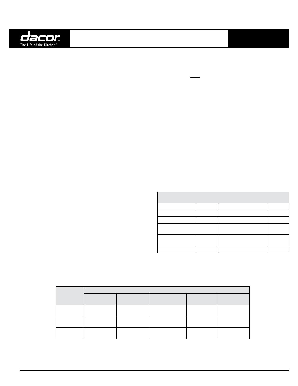
Equivalent Number of Feet -
Duct Elbows and Transitions
45° elbow, 8 inch 3 feet 3 ¼” X 10”, 45° elbow 7 feet
45° elbow, 10 inch 2 feet 3 ¼” X 10”, 90° elbow 15 feet
90° elbow, 8 inch 7 feet 3¼”X10”,90°atelbow 20 feet
90° elbow, 10 inch 5 feet
3 ¼” X 10” to 8” round
transition
4 feet
90° 3 ¼” X 10” to
8” round transition
25 feet
3 ¼” X 10” to 10” round
transition
4 feet
Roof cap * Wall cap** *
* The equivalent lengths of roof and wall caps vary with model and
configuration. For equivalent length, contact the manufacturer or a qualified
HVAC specialist.
** Not applicable for REMP series blowers.
Duct Size
Used
Blower Maximum Duct Straight Length
REMP3
Remote Blower
REMP16
Remote Blower
ILHSF8
In-line Blower
ILHSF10
In-line Blower
CABP3
Cabinet Blower
8 Inch
50 feet
(15.2 meters)
60 feet
(18.3 meters)
50 feet
(15.2 meters)
60 feet
(18.3 meters)
40 feet
(12.2 meters)
10 Inch
40 feet
(12.2 meters)
70 feet
(21.3 meters)
40 feet
(12.2 meters)
70 feet
(21.3 meters)
30 feet
(9.2 meters)
3 ¼” X 10”
40 feet
(12.2 meters)
60 feet
(18.3 meters)
40 feet
(12.2 meters)
60 feet
(18.3 meters)
30 feet
(9.2 meters)


