Page is loading ...

Owner Instructions
Warning! Read instructions before using the machine
www.numatic.com
TT 4045
TT 4055
ET 4045
Scrubber Dryer
TT 4045
TT 4055
ET 4045

2
Index
Machine overview
Rating label / Personal Protective Equipment / Recycling
Safety Precautions / Specications
Before continuing, please refer to Set Up Guide on Page 7
!
Machine Set Up
Tilting the Handle
Fitting the Top Tank
Fitting the Brush
Tipping the Brush Deck
Fitting the Floor Tool
Fill the Clean Water Tank
Clean Water Level
Control of Cleaning substances (COSHH)
Clean Water Tap On / Off
Pre Cleaning
Pre Scrubbing
Lowering the oor tool
Breakaway oor-tool feature
Setting the cleaning controls
Regular Maintenance
Tanks and Filters
Changing the Floor Tool Blades
Trouble shooting
Wiring Diagrams
Recommended spare parts
Warranty
Declaration document
Company Addresses
Page 2
Page 3
Page 4
Page 5 / 6
Page 7
Page 7
Page 7
Page 8
Page 8
Page 9
Page 9
Page 9
Page 9
Page 10
Page 10
Page 10
Page 11
Page 11
Page 12
Page 13
Page 14
Page 15 / 16
Page 17
Page 18
Page 19
Page 20
!

3
1. Operator control panel
2. Separator
3. Top tank (waste water)
4. Waste water emptying hose
5. Bottom tank (clean water)
6. Deck locking pin
7. Brush deck
8. Handle position lever
9. Vacuum switch
10. Pump switch
11. Power Light
12. On / Off Switch
13. On / Off lever
14. Clean water tank ll point
15. Floor tool vacuum hose
16. Vacuum hose
17. Clean water tank emptying hose & ll level
18. Floor Tool Lifting lever
19. Floor tool retaining knobs
20. Semi parabolic oor-tool
21. Clean Water Filter
22. Brush
Machine Overview
1
3
4
5
6
7
8
10
13
14 15 16 17
18
19
20
21
11
2
22
9
12
13
19

4
Rating Label
WEEE (Waste, Electrical and Electronic Equipment)
Scrubber dryer Accessories and packaging should be sorted for environmentally- friendly recycling.
Only for EU countries.
Do not dispose of scrubber-dryer into household waste.
According to the European Directive 2002/96/EC on waste electrical electronic equipment and its
incorporation into national law.
Scrubber-dryers that are no longer suitable for use must be separated, collected and sent for
recovery in an Environmentally- friendly manner.
Safety Critical Component
Mains lead:
H05VV-F x 1.5 mm
2
x 3 core
About the Machine
1
2
3
4
5
6
7
8
9
1
2
3
4
5
6
7
8
9
Company Name & Address
Machine Description
Voltage Frequency
Power rating
Max Gradient
Weight (ready to use)
CE Mark
WEEE Logo
Splash Proof Rating
Machine yr/wk Serial number
Failure to rectify the problem or in the event of a breakdown contact your Numatic dealer or the
Numatic Technical help line +44 (0)1460 269268
10
10
11
12
13
11
12
13
Machine Description
Noise Rating
Hand Arm Vibration
Ear Protection Safety Footwear Head Protection Safety Gloves
Dust/Allergens
Protection
Eye Protection Protective
Clothing
Hi-Vis Jacket
Caution
wet oor sign
Note:
A risk assessment should be conducted to determine which PPE should be worn.
PPE
(Personal protective equipment) that may be required for certain operations).

5
As with all electrical equipment care and attention must be exercised at all times during its use, in addition
to ensuring that routine and preventative maintenance is carried out periodically in order to ensure its safe
operation.
Failure to carry out maintenance as necessary, including the replacement of parts to the correct standard could render
this equipment unsafe and the manufacturer can accept no responsibility or liability in this respect.
When ordering spare parts always quote the Model Number / Serial Number specied on the Rating Plate.
This appliance is not intended for use by persons (including children) with reduced physical, sensory or mental
capabilities, or lack of experience and knowledge, unless they have been given supervision or instruction concerning
use of the appliance by a person responsible for their safety.
Children should be supervised to ensure that they do not play with the appliance.
This machine is not suitable for picking-up hazardous dust.
Do not use on surfaces having a gradient exceeding that marked on the appliance.
The machine is not to be stored outdoors in wet conditions.
This machine is for indoor use only.
Read the instruction manual before using the appliance.
This product meets the requirements of IEC 60335-2-72
NOTES
This machine is also suitable for commercial use, for example in hotels, schools, hospitals, factories, shops and
ofces for other than normal housekeeping purposes.
• Ensure only competent persons unpack/assemble the machine.
• Keep your machine clean.
• Keep your brushes in good condition.
• Replace any worn or damaged parts immediately.
• Regularly examine the power cord for damage, such as cracking or ageing. If damage is found,
replace the cord before further use.
• Only replace the power cord with the correct Numatic approved replacement parts.
• Ensure that the work area is clear of obstructions and / or people.
• Ensure that the working area is well illuminated.
• Pre-sweep the area to be cleaned.
• Use steam cleaners or pressure washers to clean the machine or use in the rain.
• Attempt machine maintenance or cleaning unless the power plug has been removed from the supply
outlet.
• Allow any inexperienced repairs. Call the experts
• Strain cable or try to unplug by pulling on cable.
• Leave the brush pad on the machine when not in use.
• Allow the machine to be used by inexperienced or un-authorised operators or without appropriate training.
• Use the machine without the solution tanks properly positioned on the machine, as shown in the instructions.
• Expect the machine to provide trouble-free, reliable operation unless maintained correctly.
• Lift or pull the machine by any of the operating triggers - Use the main handle.
• Remove the handle from the machine except for service and repair.
• Use on surfaces having a gradient exceeding that marked on the machine.
ORIGINAL INSTRUCTIONS
READ MANUAL BEFORE USE
Information for Scrubber Dryer
Component Interval Inspect for
Mains Lead DAILY Scufng, cracks, splits, conductors showing
Brushes DAILY Bristle damage, wear, drive collar wear
Squeegee Blade BEFORE EACH USE Wear, cracks, splits
Filters BEFORE EACH USE Clogging and debris retention
Tanks AFTER EACH USE Rinse dirty water tank after use
WARNING
CAUTION
DO
DON’T

6
Do not use on surfaces have a gradient exceeding that marked on the machine.
Only use brushes provided with the appliance or those specied in the instruction manual.
The use of other brushes may impair safety.
A full range of brushes and accessories are available for this product.
Only use brushes or pads which are suitable for the correct operation of the machine for the specic task being
performed.
It is essential that this equipment is correctly assembled and operated in accordance with current safety regulations.
When using the equipment always ensure that all necessary precautions are taken to guarantee the safety of the
operator and any other persons who may be affected.
Wear non-slip footwear when scrubbing. Use a respiratory mask in dusty environments.
The machine, while charging, must be positioned so that the mains plug is easily accessible.
When cleaning, servicing or maintaining the machine, replacing parts or converting to another function the power
source shall be switched off.
Mains operated machines shall be disconnected by removing the power plug, and battery operated machines shall be
disconnected by switching off the isolating key.
Machines left unattended shall be secured against unintentional movement.
Operators shall be adequately instructed as to the correct use of the machine.
WARNING
Data
Brush Motor Vac Motor Power Sound
Pressure
Speed Brush Dimensions
1500W 1000W 220-240v 50Hz
220v 60Hz
120v 60Hz
110v 50Hz
80 dB(A) 50Hz = 150rpm
60Hz = 180rpm
450mm Width - 470 mm
Length - 890 mm
Height - 1180 mm
Gross Weight
Full
Protection Class Hand Arm
Vibration
Pad Net Weight Cleaning
Range
Water Capacity
97 Kg Class 1 1.4 +/- 0.05ms² 400 mm 57 Kg 42m 40 L
TT 4045
Brush Motor Vac Motor Power Sound
Pressure
Speed Brush Dimensions
1500W 1000W 220-240v 50Hz
220v 60Hz
120v 60Hz
110v 50Hz
80 dB(A) 50Hz = 150rpm
60Hz = 180rpm
550mm Width - 570 mm
Length - 1030 mm
Height - 1180 mm
Gross Weight
Full
Protection Class Hand Arm
Vibration
Pad Net Weight Cleaning
Range
Water Capacity
97 Kg Class 1 1.4 +/- 0.05ms² 500 mm 57 Kg 42m 40 L
TT 4055
Brush Motor Vac Motor Power Sound
Pressure
Speed Brush Dimensions
1500W 1000W 220-240v 50Hz
220v 60Hz
120v 60Hz
110v 50Hz
80 dB(A) 50Hz = 150rpm
60Hz = 180rpm
450mm Width - 470 mm
Length - 890 mm
Height - 1180 mm
Gross Weight
Full
Protection Class Hand Arm
Vibration
Pad Net Weight Cleaning
Range
Water Capacity
97 Kg Class 1 1.4 +/- 0.05ms² 400 mm 57 Kg 42m 40 L
ET 4045

7
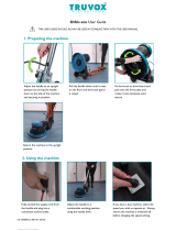
Machine Set Up
Please read before commencing any operation.
After the removal of all the packaging, carefully open and check the contents.
!
Fit the top tank to the machine
(g 3).
Fit both the vacuum hose and the
oor tool hose to the separator
(g 4).
Fitting top tank
Fitting the brush
Featuring the Nulock brush system.
The brush is simply pushed and twisted to lock, making tting and removal a simple process.
The Pad is retained using Numatic’s own PadLoc system. (Ask your supplier for details)
Only use manufacturer supplied brushes / pads.
TT 4045 / ET 4045 requires a 450mm brush or a 400mm pad.
TT 4055 requires a 550mm brush or a 500mm pad
Safety gloves are recommended for the changing of used brushes.
Fit the brush /pad to the drive chuck,
twist to lock the brush
(Fig 5) / pad in place (Fig 6).
Fig 6
Fig 5
!
Tilting the handle
Using the handle position lever
(g 1).
Move the handle into the upright
position (g 2).
Fig 1 Fig 2
Fig 3 Fig 4

8
Machine Set-Up
Fitting the Floor Tool
The oor tool has been designed for quick tting, allowing easy squeegee blade replacement and a safety knock-off
feature if the oor tool gets snagged, whilst in transit.
Raise the oor tool for transit or lower for cleaning operation using the lifting
handle tted to the back of the machine (Fig 11).
For tting the oor tool blades (See Page 13)
Note:
It is easier to t the oor-tool if the weight of the machine is resting on the brush. Ensure the brush is tted rst.
Fig 11
Fig 10
Fig 9
Fit the oor tool and retain using
the detent pin (g 9).
The lifting strap is held by a
detent pin (Fig 10).
Note:
Raise oor-tool again before driving to the cleaning area
Tipping the Brush Deck
To tip the deck into the down position
(Operating mode). Press in the brush
deck locking bar (Fig 7) and rotate the
brush deck (Fig 8).
To change to brush deck up position,
(Transit mode) simply lift the deck and
the sprung loaded locking bar will active
to hold the deck up.
Fig 8
Fig 7
ALWAYS ENSURE THAT THE MACHINE IS SWITCHED OFF
BEFORE MAKING ANY ADJUSTMENTS
!

9
The water level in the clean water tank can be seen using the clean-water clear
dump hose tted to the rear of the machine.
The clean water bottom tank holds 40 litres.
Machine Set-Up
Control of Substances Hazardous to Health (COSHH)
For best results use a non-foaming type of chemical, dilute to the manufacturers specication.
For further guidance on hazardous substances refer to health and safety instructions online.
Visit http://www.hse.gov.uk/ for UK information.
Important
Do not operate machine unless the Operator Manual has been read and fully understood.
!
!
WHEN HANDLING AND MIXING CHEMICALS.
Always ensure that chemical manufacturers safety guidelines are followed.
Only use chemicals recommended for use in auto scrubber-dryers.
! !
Note.
Great care must be taken to ensure that contaminants (leaves,hair, dirt, etc) are not allowed to enter the
clean-water during the lling process.
If using a bucket or similar, ensure it is always clean and free from debris.
Clean water level
The TT / ET Range are all equipped with a 40 litre clean-water tank allowing large areas to be cleaning in a single ll.
Filling the clean-water tank
To ll the clean-water tank, use the 1 meter FLEXI
- FILL pipe from either a tap or hose pipe (Fig 12).
The large cap can also be unscrewed for lling
from a bucket or suitable
container.
Fill the clean water tank to a maximum of 40 litres,
including cleaning chemicals if required.
Follow chemical manufacturing guide lines.
The clear Dump hose at the rear of the machine can be used to see the level of the clean water.
Fig 12
Turn on the clean water tap
On
Off
Clean water tap

10
Lowering the oor tool
Fig.16
After preparing the oor (see previous section), we are now ready to set the controls to suit the cleaning conditions.
Before any settings can be applied, ensure the brush deck is lowered.
Move the Floor tool lever (see g.16), to it’s lower position (see g.17).
Note: The machine will still reverse with the oor tool in the lowered position, this could possibly damage the
blades. Raise the oor tool before reversing.
Fig.17
Machine Operation
Pre-scrub mode
The TT / ET Range have been designed to cope with a variety of oor types and different levels of soiling.
On heavily soiled oors use a ‘double scrub’ technique.
First pre-scrub the oor with the oor-tool in the raised position, allow the chemical time to work, then scrub the area a
second time with the oor-tool lowered.
The clean-water / chemical mix is
dispersed via ‘THRU-FEED’ system.
The waste water is then retrieved by
the oor-tool.
Overlap the scrubbing path by 10cm
to ensure an even clean (Fig 14).
If streaking occurs, wipe the oor-tool
blades clean (Fig 15).
Floor tool in use
Fig 15
ALWAYS ENSURE THAT THE FLOOR IS PRE-SWEPT
AND RELEVANT SAFETY SIGNS ARE DISPLAYED.
! !
Numatic part (629044) Wet Floor sign
(available if required)
Pre-cleaning advice.
Before performing the cleaning operation, place out
appropriate warning signs and sweep or dust-mop the oor
(Fig 13).
Fig 13
Fig 14

11
1 1
Setting the cleaning controls
To start: hold down either trigger and press the yellow start button once
2
Ensure your TT / ET machine has been plugged into a suitable power
supply.
Select the desired function using the ON / OFF switches tted to the
handle.
Breakaway oor-tool
Fig.18
The oor-tool design incorporates a breakaway feature.
Allowing it to safely disengage from its mounting should it
become caught on an obstruction, during forward machine
movement.
To re-attach the blade to its holder.
First loosen the retaining knobs on the oor-tool body and slide
onto the holding bracket.
Tighten retaining knobs to nger tight. (See g.18)
Note Care must be taken to reduce speed when cornering or when manoeuvring around obstacles.

12
ALWAYS ENSURE THAT THE BATTERY IS DISCONNECTED
PRIOR TO ANY MAINTENANCE OPERATION
! !
After use, empty waste-water tank using
emptying hose and ush-out with clean
water (Fig 19).
A
Remove the two hoses to disconnect the separator from the
machine (Fig 20).
Lift off the separator. The separator has a sealing-rubber
which should be examined at every clean-down (Fig 21).
Rinse using clean water.
The TT / ET Range has been designed with ease of use in mind, this included easy stripping-down and cleaning.
Remove the lter tted into the separator and ush with clean water (Fig 22)(Fig 23).
Placed into the top tank is grey lter basket, clean and ush with clean water (g 24) (Fig 25).
A
Regular Maintenance
The Bottom (Clean Water) tank is attached to the chassis and should only
be removed by a competent service engineer (Fig 26).
Clean by ushing with clean water if required.
Excess water can be drained using the clear dump hose tted to the rear
of the machine.
Located under the left hand side is a clean water lter, ensure the clean
water tap is turned off before removing this lter (Fig 27).
Clean and ush with clean water if required.
Fig 19
Fig 20
Fig 21
Fig 22
Fig 23
Fig 26
Fig 24
Fig 25
Fig 27

13
! !
ALWAYS ENSURE THAT THE BATTERY IS DISCONNECTED PRIOR TO ANY
MAINTENANCE
Note:
The blades are designed to be reversible, thus extending their useful working life.
Changing the Floor Tool Blades
The oor-tool
Fig.29
Fig.30
Fig.28
To clean the oor-tool, remove securing-pin and disconnect the lifting strap and remove the oor tool securing pin
pull-free the oor tool from the rear of the machine.
Rinse the oor-tool assembly with clean water and ret.
Periodically the oor-tool blades should be examined and checked for wear and damage.
The blade removal is easy. Simply start by removing the four retaining pins (see Fig 28), turn the oor-tool over and
separate the blade carrier from the body (see Fig 29). Peel away the blades from their locating lugs (see Fig 30) and
examine or renew as required.
Replacement is a reversal of the removal process.
Floor-tool overview
1. Floor-tool main body
2. Rear blade
3. Blade carrier
4. Front blade (slotted)
5. Retaining pins x 4
1
2
3
4
5
The TT range is provided with the aluminium oor tool shown.
The ET range is provided with the Eco Range oor tool.

14
Trouble-Shooting
Failure to rectify the problem or in the event of a breakdown contact your Numatic dealer
or the Numatic Technical helpline +44 (0)1460 269268
( see back page for company addresses or dealers stamp)
PROBLEM CAUSE SOLUTION
Poor water pick-up Waste-water tank full
Clogged / blocked vacuum hose
Loose hose connections
Debris basket lter clogged/blocked
Separator lter clogged / blocked
Poor separator seal
Damaged separator seal
Damaged / split vacuum hose
Damaged oor-tool blades
Empty waste-water tank (page 12)
Remove and clean
Push tight connections
Remove and clean (page 12)
Remove and clean (Page 12)
Clean and ret (page 12)
Renew (contact service dept)
Renew (contact service dept)
Renew (contact service dept)
No brush / scrub function No brushes tted
Brush deck raised
Check and t (page 7)
Lower brush deck (page 8)
Little or no water ow Clean-water tank empty
Clean-water tank lter blocked/ clogged
Brush deck raised
Fill clean-water tank (page 9)
Remove and clean (12)
Lower brush deck (page 8)
Note
........................................................................................................
........................................................................................................
........................................................................................................
........................................................................................................
........................................................................................................
........................................................................................................
........................................................................................................
........................................................................................................
Daily
Keep the machine clean
Ensure brushes/ pads/ squeegee/ lters are in good condition
Check for any worn or damaged parts and replace immediately
Drain and rinse dirty water tank after every use
Store machine with brush deck secured in tilted position
Weekly – as daily and –
Check brush or pad and skirt and rinse
Check oor tool blades for wear and wipe clean
Clean separator assembly including lter and check condition of seal
Flush out system with clean water and clean lters
Do not steam clean or pressure wash
Twin Tec
Maintenance

15
TT 4045 / TT 4055 / ET 4045 220v ~ 230v
DRW - 11855 (A02) 25/10/2012

16
TT 4045 / TT 4055 / ET 4045 110v~50Hz
DRW - 12474 (A02) 25/10/2012

17
Spare Parts
577859 Top Tank - Blue 208638 Wheel
577860 Bottom Tank - Blue 577864 Deck
577839 Separator 577893 Handle
206265 Barrel Filter 321934 Vac Motor
207000 Basket Filter 236012 Mains Cable UK
208588 Vac Hose 236132 Mains Cable Euro
208624 Floor Tool Hose 236020 Mains Cable Switzerland
213047 Dump Hose Top 577856 Floor Tool
303641 Dump Hose Bottom 206953 Detent Pin
606203 450mm Polysrub Brush 606401 410 Padloc Drive Board
606204 450mm Nyloscrub Brush 606306 450mm Long Life Brush
606202 450mm Union Mix Brush 606196 Recommended oor tool Blade Set
606157 Optional Polyurethane Floor Tool Blade Set
577859 Top Tank - Blue 208638 Wheel
577860 Bottom Tank - Blue 577870 Deck
577839 Separator 577893 Handle
206265 Barrel Filter 321934 Vac Motor
207000 Basket Filter 236012 Mains Cable UK
208588 Vac Hose 236132 Mains Cable Euro
208624 Floor Tool Hose 236020 Mains Cable Switzerland
213047 Dump Hose Top 577922 Floor Tool
303641 Dump Hose Bottom 206953 Detent Pin
606028 550mm Polysrub Brush 606403 508 Padloc Drive Board
606550 550mm Nyloscrub Brush 606551 550mm Long Life Brush
606196 Recommended Linatex Floor tool Blade Set 606157 Optional Polyurethane Floor Tool Blade Set
577875 Top Tank - Red 208638 Wheel
577876 Bottom Tank - Red 577864 Deck
577839 Separator 577894 Handle
206265 Barrel Filter 207000 Basket Filter
208588 Vac Hose 321934 Vac Motor
208624 Floor Tool Hose 236012 Mains Cable UK
213047 Dump Hose Top 236132 Mains Cable Euro
303641 Dump Hose Bottom 236020 Mains Cable Switzerland
229295 Floor Tool Retaining Pin 577931 Floor Tool
606401 400 Padloc Drive Board 606306 450mm Long Life Brush
606203 450mm Polysrub Brush 606202 450mm Union Mix Brush
606204 450mm Nyloscrub Brush 606157 Optional Polyurethane Floor Tool Blade Set
606196 Recommended oor tool Blade Set
TT 4045
TT 4055
ET 4045

18

19
EU Declaration of Conformity
EU DECLARATION OF CONFORMITY
We hereby declare that the following equipment ful ls all the
relevant provisions of:
Machinery Directive 2006/42/EC
EMC Directive 2004/108/EC
Machine Description: Scrubber Dryer
Type: TT, ET series
Manufactured by: Numatic International Limited
This equipment has been designed and manufactured in
accordance with the following standards:
IEC 60335-1:2010
IEC 60335-2-72:2002 +A1
IEC 62233:2005
EN 55014-1:2006
EN 55014-2:1997+A1
EN 61000-3-2:2006
EN 61000-3-3:1995+A1+A2
A technical construction le for this equipment is retained at
the manufacturer’s address.
Signed:
Date: 28/08/2012
Name:Allyn Boyes
Position: Technical Manager
Numatic International Limited,
Chard , Somerset.
TA20 2GB
www.numatic.co.uk
GB
12

20
Numatic International Limited, Chard, Somerset, TA20 2GB, ENGLAND.
Telephone 01460 68600 Fax: 01460 68458 www. numatic.co.uk
Subject to change without prior notice.
Distributed by
TT 4045 / TT 4055 / ET 4045
244063 0113 (A02)
This machine has been packed with
the following items
Brush
Floor Tool
Hose Hook
38 mm / 32 mm Adaptor
Signed
/