FIGURES FIGURES FIGURAS
Attaching the bracket
Fixation du support
Fijación del Partidor
1
2
Instalación
Importante: Lea detenidamante todas las instrucciones antes de instalar el partidor de bombas. Siga todas las normas locales para
instalación eléctrica y requerimientos. Ante cualquier duda consulte a un eléctrico calificado acerca de los requerimientos necesarios
para la instalación.
1. Selección de una ubicación
Corte toda la electricidad desde el circuito principal, y agregue un elemento seguro de corte. El partidor de
bombas necesita de un circuito especial, no ocupe el mismo circuito para la bomba y el programador de riego.
Determine la ubicación deseada para el partidor de bombas. El partidor debe ser instalado 1,5 metros alejado
del programador de riego, el programador de riego debe estar a más de 3.5 metros de distancia de la bomba.
Para evitar sobrecalentamiento el Partidor no debe estar expuesto directamente al sol.
2. Fijación del Partidor
fije mediante el agujero que esta por detrás del Partidor utilizando los tornillos incluidos. (ver ilustración Nº 2)
3. Conectando los cables
Remueva la tapa frontal del Partidor . Destornille los cuatro tornillos ubicados en las esquinas de la caja.
Determine la ubicación deseada para la entrada de los cables desde la fuente de poder, la ubicación de los
cables hacia la bomba y la entrada de los cables desde el programador.
Use un destornillador y martillo para remover material y ubicar correctamente el orificio fijado
Fije el partidor a la pared usando tornillos Nº 8 (no incluidos). Use tarugos en muros de albañilería. Sobre 6
tornillos pueden ser usados para montar el partidor de bombas (ver ilustración 3)
Fije los conductos y fittings apropiados para las conexiones (según las normas locales)
Instale los cables de corriente de entrada (12 awg 155(F/75C)) y conéctelos en el partidor para bombas. El
partidor tiene debidamente señalizado el lugar donde van los cables de entrada "in" y los salida hacia la
bomba "Out". Use los conectores roscados proporcionados para hacer las conexiones. Asegúrese de que los
cables estén siempre protegidos. Conecte los cables a tierra (ver ilustración 4)
Instale los cables de corriente débil desde el programador (16-24 awg 155(F/75C)) y conéctelos en el par-
tidor para bombas. El partidor tiene debidamente señalizado el lugar donde van los cables de entrada del
programador con 24 V. Use los conectores roscados proporcionados para hacer las conexiones.
Revise bien cada conexión para verificar que cada cable este correctamente conectado.
4. Reinstalando la caja partidora
Apriete los tornillos hasta que queden bien ajustados, no sobre apriete para evitar roturas.
Conecte los cables desde el programador de riego al partidor, un cable debe ir desde la salida que dice "pump"
o "master valv", y el otro cable desde la salida que dice "com" o "common". (ver ilustración 5)
5. Probando el sistema
Vuelva a dar energía y pruebe el sistema
Peligro! Siempre se debe cortar el suministro eléctrico antes de abrir la tapa del partidor! Nunca se debe abrir la tapa del partidor
mientras riega! No exceda el rango máximo de voltaje o caballos de fuerza recomendados (2 HP con 220 Volt, o 1 HP con 120 Volt),
no exceda el voltaje recomendado desde el programador de 30 Volt AC
ESPAÑOL
ESPECIFICACIONES DE PARTIDOR
ESPECIFICACIONES DEL TRANSFORMADO
CERTIFICACIÓN Y APROBACIONES
INCLUYE
HERRAMIENTAS REQUERIDAS
NO INCLUIDOS
1 HP con 120 V una fase
2 HP con 240 V una fase
25 A con 240 V
UL, CUL
2 sujetadores para montaje
4 sujetadores para tornillos
7 conectores roscados
4 enrosque las anclas
4 No. 8 tornillos que montan
Cable
Martillo
Destornillador
Sacacables
24 VAC 3 VA
Voltaje mínimo 19 VAC
Voltaje máximo 30 VAC
Connecting the wires
Raccordement des fils
Conectando los cables
Sample Layout
Tracé d'Echantillont
Pruebe la disposición
Installation
Important: Read all of the instructions before installing the Pump Start Relay. Follow all local wiring codes and requirements. Have a
qualified electrician install the relay if there are any questions about the requirements for proper installation.
1. Selecting a Location
Tu rn off the power at the main circuit breaker panel, and attach an appropriate safety lockout device. The
pump may require at dedicated circuit. Do not have the pump and sprinkler controller on the same circuit.
Determine the desired location for the Pump Start Relay box. It should be mounted 5 feet away from the sprin-
kler controller. The sprinkler controller should be mounted at least 12 feet away from the pump. To help pre-
vent overheating the Pump Start Relay box should not be mounted in direct sunlight.
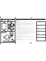
2. Attaching the bracket
Attach the mounting clips to the back of the relay box using the screws included. (See Illustration 1)
3. Connecting the Wires
Remove the relay box cover. Unscrew the four screws located on the corners of the box.
Determine the desired location for the incoming AC power wires, the location for the wires to the pump, and
the location for the wires to the timer.
Use a screwdriver and hammer to remove the desired conduit knockout plugs.
Attach the relay box to the wall using either the mounting template or the corner holes with the No. 8 screws.
Use expanding anchors in plaster or masonry. Up to six screws can be used for mounting the relay box. (See
Illustration 1)
Attach the appropriate conduit fittings to the box (Follow local code requirements).
Run the AC wires of AWG 12 with a temperature rating of 155º F/68º C into the relay box and connect them
to the appropriate relay wires. The wires are labeled "power in" from main power source, and "power out" to
pump (refer to diagram on housing unit). Use the wire nuts provided to make the connection. Make sure
there is no bare wire exposed. Connect the ground wires. (See Illustration 2)
Run the sprinkler controller wires of AWG 16-24 (155º F/68º C) into the box and connect them to the relay
wires labeled 24V. Use wire nuts to make the connections.
Re-inspect each connection to ensure the wires are properly connected.
4. Re-install the box cover
Tighten the screws until they are snug, but do not over tighten or the screws may break.
5. Connect the sprinkler controller
Connect the sprinkler controller wires to the controller by connecting one wire to the terminal labeled
“Pump” or “Master Valve”. The other wire should be connected to the terminal label “Com” or “Common”.
6. Test the System
Tu rn the power back on and test the system.
Warning! Always shut off the power supply before opening the relay box cover! Never open the relay box cover when it is raining! Do
not exceed the maximum recommended voltage or horsepower rating (2HP at 240V, or 1HP at 120V)! Do not exceed the coil maximum
recommended voltage of 30 VAC!
ENGLISH
RELAY SPECIFICATIONS
COIL SPECIFICATIONS
APPROVAL AND CERTIFICATIONS
INCLUDES
TOOLS REQUIRED
NOT INCLUDED
1 HP at 120 V Single Phase
2 HP at 240 V Single Phase
25 A at 240 V
UL, CUL approved
2 mounting clips
4 mounting clip screws
7 wire nuts
4 screw anchors
4 No. 8 mounting screws
Wire
Hammer
Screwdriver
Wire strippers
24 VAC 3 VA
Minimum voltage 19 VAC
Maximum voltage 30 VAC
Installation
Important : lisez l'ensemble des instructions avant d'installer le relais de démarrage de pompe. Respectez tous les codes et indications
nationaux relatifs au câblage. Faîtes installer le relais par un électricien qualifié en cas de doute concernant les normes d'une installa-
tion adéquate.
1. Sélectionner un emplacement
Coupez le courant au niveau du panneau principal à disjoncteur et fixez un dispositif d'interrupteur de sécu-
rité approprié. La pompe peut nécessiter un circuit spécialisé. Elle ne doit pas être fixée sur le même circuit
que le programmateur d'arroseur.
Déterminez l'emplacement souhaité pour le boîtier relais de démarrage de pompe. Il doit être monté à plus de
1,5 m (5 pieds) du programmateur d'arroseur. Ce dernier ne doit pas se situer à moins de 3,65 m (12 pieds)
de la pompe. Pour éviter la surchauffe, le boîtier relais de démarrage de pompe ne doit pas être monté à un
endroit exposé directement à la lumière du soleil.
2. Fixation du support
Fixez les brides de montage à l'arrière du boîtier de relais à l'aide des vis fournies. (Voir Illustration 1)
3. Raccordement des fils
Ouvrez le couvercle du boîtier de relais. Desserrez les quatre vis situées dans les angles du boîtier.
Déterminez l'emplacement souhaité pour les fils entrants de l'alimentation électrique, pour les fils menant à
la pompe et pour les fils menant au programmateur.
À l'aide d'un tournevis et d'un marteau, retirez les bouchons souhaités d'éjecteur du conduit.
Fixez le boîtier de relais au mur à l'aide d'une vis n° 8 (non fournie). Utilisez les chevilles à gaine d'expansion dans
le plâtre ou la maçonnerie. Vous pouvez utiliser jusqu'à six vis pour monter le boîtier de relais. (Voir Illustration 1)
Fixez les raccords de conduit appropriés au boîtier (respectez la réglementation locale).
Mettez en place les fils de l'alimentation électrique (AWG 12 155(F/75(C) dans le boîtier de relais et raccordez-
les aux fils appropriés du relais. Les fils sont étiquetés de telle sorte que l'alimentation principale provienne de
la principale source de courant et mène à la pompe. Utilisez les serres-fils fournis pour effectuer les raccorde-
ments. Veillez à ce qu'aucun fil dénudé ne soit exposé. Raccordez les fils à la terre. (Voir Illustration 2)
Mettez en place les fils de programmateur d'arroseur (AWG 16 à 24 155(F/75(C) dans le boîtier puis reliez-les
aux fils de relais étiquetés 24 V. Utilisez les serres-fils fournis pour effectuer les raccordements.
Inspectez à nouveau la connexion afin de vous assurer que les fils sont correctement connectés.
4. Remettez en place le couvercle du boîtier
Serrez les vis à fond mais sans excès car elles peuvent se briser.
5. Connecter le contrôleur d'arroseur
Connectez les fils du programmateur d'arroseur au contrôleur en reliant un fil au terminal portant l'étiquette
"Pompe" ou "Vanne maîtresse". L'autre fil doit être raccordé au terminal portant l'étiquette “Com” ou “Commun”.
6. Mise à l’essai de l’installation
Remettez le système sous tension et testez-le.
Avertissement ! Coupez toujours le courant avant d'ouvrir le couvercle du boîtier de relais ! N'ouvrez jamais ce couvercle par temps
pluvieux ! Ne dépassez pas la tension maximum recommandée ou la puissance nominale (2 ch.-v. à 240 V ou 1 ch.-v. à 120 V) ! Ne
dépassez pas la tension maximum recommandée de la bobine de 30 VCA !
FRANÇAIS
SPÉCIFICATIONS DU RELAIS
SPÉCIFICATIONS DE BOBINE
AGRÉMENTS ET CERTIFICATIONS
INCLUS
OUTILS NÉCESSAIRES
NON INCLUS
1 ch.-v. à 120 V courant monophasé
2 ch.-v. à 240 V courant monophasé
25 A à 240 V
Agréé UL, CUL
2 brides de montage
4 colliers de serrage à vis de montage
7 serres-fils
4 la vis ancre
4 No 8 vis qui montent
Fils
Marteau
Tournevis
Outils à dénuder
24 VCA 3 VA
Tension minimum 19 VCA
Tension maximum 30 VCA
WTM220331 57009-20 rD.qx 1/29/02 1:04 PM Page 2


 1
1
 2
2


Orbit 27918 Installation guide
Orbit Watermaster 57012 Installation and User Manual
Orbit B-hyve 57946 User manual
Orbit 57900 User manual
Orbit 91880 User manual
Rain Bird ESP-Me Advanced User's Manual
Toro ECXTRA User manual
Hunter X-CORE Owners Manual And Programming Instructions
 Rachio 16RACHBX Installation guide
Rain Bird ESP-TM2 User manual
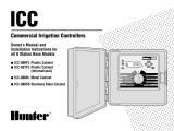 Hunter Fan ICC-801PL User manual
 Rachio 8ZULW-B User guide


