English HPC COMPASS
13-8
performed. When activated, you can stop the automatic compass
deviation at any time with a LONG press on SET.
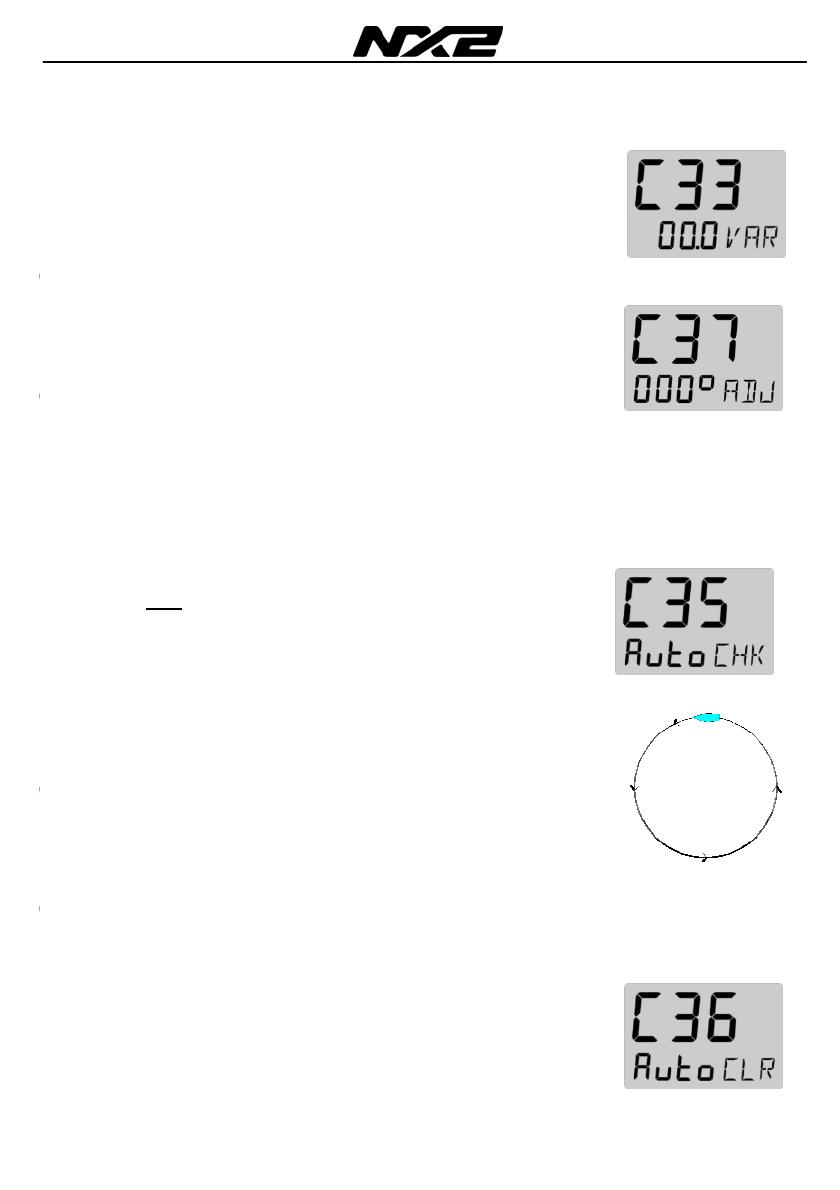
3.1.3 C33 Magnetic deviation (00.0 VAR)
Magnetic variation. Maximum +/- 99.9°.
Easterly variation = underlining ( _ ) sign.
Westerly variation = minus ( - ) sign.
The local magnetic variation is usually printed in the sea chart.
3.1.4 C37 Compass misalignment correction (Adj)
Compass transducer misalignment correction or the so called
”A-fault”. Can be set between 000°and 359°. Allows 180°
reversed mounting if needed. Never mount the transducer in a
90° position relative to the boats fore-aft line.
To check the transducer position, sail/drive your boat in a straight
line towards two visible objects in a line.
Example: If the actual heading taken from the sea chart is 330°
and the compass displays 335°, then set calibration code C37
value to 360° - 5° = 355°.
3.1.5 C35 Automatic compass deviation check (Auto CHK)
(Auto CHK) is done by driving the boat in a circle up to 1 ¼
turn, after
(Auto DEV) is performed. The result will be
compared with (Auto DEV). If the deviation is less than 1,5*,
the average value from the comparison between (Auto DEV)
and (Auto CHK) will be stored.
If the check is OK, (Auto CHK) will be displayed.
If not an error message will be displayed.
Select automatic compass check (Auto CHK), press SET and
repeat the same circle manoeuvre as described in the (Auto DEV)
routine.
Note: As soon as you place any kind of ferrous items close to the
compass, the (Auto DEV) / (Auto CHK) routines should be
repeated. So if you have packed your boat for the vacation, think
about where you place ferrous items in relation to the compass
transducer.
3.1.6 C36 Cancel earlier performed compass deviation (Auto CLR)
To cancel/clear earlier (Auto DEV), press SET.


