Page is loading ...

May
1974
FORM:
OM-342
Effective
with
serial
No.
HE756343
MODEL
430
SCM
430
SCM/S
STOCK
NO.
901
379
900785
MODEL/STOCK
NO.
SERIAL/STYLE
NO.
DATE
PURCHASED
OWNERS
MANUAL
fi
MILLER
ELECTRIC
MFG.
CO.
APPLETON,
WISCONSIN;
USA
54911
ADDITIONAL
COPY
PRICE
$1.15
NWSA
CODE
NO.
4579
U.S
A.

WARRANTY
H
MILLER
Electric
Mfg.
Co.,
Appleton,
Wisconsin,
warrants
all
new
equipment
to
be
free
from
defects
in
c
material
and
factory
workmanship
for
the
periods
indicated
below,
provided
the
equipment
is
installed
and
operated
according
to
manufacturers
instructions.
c
~
C
C
c
~
C
C
MILLER
Electric
Mfg.
Co.s
obligation,
under
this
warranty,
is
limited
to
replacing
or
repairing
any
defective
part
or
correcting
any
manufacturing
defect
without
charge
during
the
warranty
period
ifMILLERS
inspec
c
tion
confirms
the
existence
of
such
defects.
MILLERS
option
of
repair
or
replacement
will
be
f.o.b.
factory
at
Appleton,
Wisconsin
or
f.o.b.a
MILLER
authorized
servicefacility,andthereforenocompensationfortrans
~
portationcostsofanykindwillbeallowed.
C
~
I
C
C
The
warranty
period,
beginning
on
the
date
of
sale
to
the
original
purchaser-user
of
the
equipment,
will
be
as
c
follows:
C
1.
Arc
welders,
power
sources,
and
components
1
year
C
2.
Original
main
power
rectifiers
3
years
(unconditionally)
3.
MHFC-L1
Feeder,
MHG-35C1,
20E,
20K,
C
and
all
guns
and
torches
90
days
C
C
4.
All
other
Millermatic
Feeders
1
year
5.
MagDiesel
engine
on
DEL-200
6
months
6.
All
other
engines
1
year
C
Engine
Warranties
are
covered
by
the
engine
manufacturers,
subject
to
their
procedures
and
to
be
handled
through
their
authorized
local
Service
Stations
or
agencies.
No
warranty
will
be
made
in
respect
to
trade
accessories,
such
being
subject
to
the
warranties
of
their
respective
manufacturers.
MILLER
Electric
Mfg.
Co.
will
not
be
liable
for
any
loss
or
consequential
damage
or
expense
accruing
directly
or
indirectly
from
the
use
of
equipment
covered
in
this
warranty.
C
CD
C
C
CD
This
warranty
supersedes
all
previous
MILLER
warranties
and
is
exclusive
with
no
other
guarantees
or
C
warranties
expressed
or
implied.
c
OPTIONAL
ACCESSORIES
No.
1A
Running
Gear
(Stock
No.
040
008)
Four
steel
wheels
8
diameter.
Carries
welder
only
No.
1ACR
Running
Gear
(Stock
No.
040
047)
No.
1A
running
gear
with
cylinder
carrying
rack,
No.
2A
Running
Gear
(Stock
No.
040
013)
Four
solid
rubber
tired
wheels
8
diameter.
Carries
welder
only.
No.
2ACR
Running
Gear
(Stock
No.
040
452)
No.
2A
running
gear
with
cylinder
carrying
rack.
No.
3
Running
Gear
(Stock
No.
040
016)
Three
pneumatic
rubber
tired
wheels
16
diameter.
Will
carry
welder,
gas
cylinders,
and
water
coolant
system.
RHC-3-100
(Stock
No.
040
279)
Remote
hand
amperage
control
with
20
cable
and
plug.
RFC-3A-100
(Stock
No.
040
399)
Remote
foot
amperage
control.
Furnished
with
20
cable
and
plug.
RFC.23A-100
(Stock
No.
040
277)
Remote
foot
amperage
and
contactor
control.
Furnished
with
20
cables
and
plugs.
RFS-2.100
(Stock
No.
040
278)
Maintained
contact
type
foot
operated
switch
for
A
panel
operation
or
can
be
converted
to
a
momentary
contact
switch
for
B
type
operation.
Furnished
with
20
cable
and
plug.

~L_~
~P
~
~;~
~~&P
~~&P
I&~
~~
~m$~
LIMITED
WARRANTY
EFFECTIVE:
NOVEMBER
1,
1976
This
warranty
supersedes
all
previous
MILLER
warranties
and
is
ex
elusive
with
no
other
guarantees
or
warranties
expressed
or
implied.
LIMITED
WARRANTYMiller
Electric
Mfg.
Co.,
Apple-
3.
All
welding
guns
and
feeder/guns
90
days
ton,
Wisconsin
warrants
to
Customer
that
all
new
and
unused
4.
All
other
Millermatic
Feeders
.
.
.
1
year
Equipment
furnished
by
Miller
is
free
from
defect
in
workman-
provided
that
the
user
so
notifies
Miller
in
~iti~
within
thirty
ship
and
material
as
of
the
time
and
place
of
delivery
by
Miller.
(30)
days
of
the
date
of
such
failure.
No
warranty
is
made
by
Miller
with
respect
to
engines,
trade
accessories
or
other
items
manufactured
by
others.
Such
engines,
trade
accessories
and
other
items
are
sold
subject
to
the
warran-
ANY
EXPRESS
WARRANTY
NOT
PROVIDED
HEREIN
9
ties
of
their
respective
manufacturers,
if
any.
At
the
present
time,
AND
ANY
IMPLIED
WARRANTY,
GUARANTY
OR
REP-
the
manufacturers
warranty
on
the
Mag-Diesel
engine
on
DEL-
RESENTATION
AS
TO
PERFORMANCE,
AND
ANY
200
is
limited
to
six
months
and
on
all
other
engines
to
one
year.
REMEDY
FOR
BREACH
OF
CONTRACT
WHICH,
BUT
In
the
case
of
Millers
breach
of
warranty
or
any
other
duty
FOR
THIS
PROVISION,
MIGHT
ARISE
BY
IMPLICA
with
respect
to
the
quality
of
any
goods,
the
exclusive
remedies
TION,
OPERATION
OF
LAW,
CUSTOM
OF
TRADE
OR
9
therefor
shall
be,
at
Millers
option,
(1)
repair
or
(2)
replace-
COURSE
OF
DEALING,
INCLUDING
ANY
IMPLIED
ment
or,
where
authorized
in
writing
by
Miller
in
appropriate
WARRANTY
OF
MERCHANTABILITY
OR
OF
FITNESS
cases,
(3)
the
reasonable
cost
of
repair
or
replacement
at
an
FOR
PARTICULAR
PURPOSE,
WITH
RESPECT
TO
ANY
authorized
Miller
service
station
or
(4)
payment
of
or
credit
for
AND
ALL
EQUIPMENT
FURNISHED
BY
MILLER
IS
the
purchase
price
(less
reasonable
depreciation
based
upon
EXCLUDED
AND
DISCLAIMED
BY
MILLER.
actual
use)
upon
return
of
the
goods
at
Customers
risk
and
ex
pense.
Upon
receipt
of
notice
of
apparent
defect
or
failure,
EXCEPT
AS
EXPRESSLY
PROVIDED
BY
MILLER
IN
~1
Miller
shall
instruct
the
claimant
on
the
warranty
claim
proce-
WRITING,
MILLER
PRODUCTS
ARE
INTENDED
FOR
ULTIMATE
PURCHASE
BY
COMMERCIAL/INDUS
dures
to
be
followed.
TRIAL
USERS
AND
FOR
OPERATION
BY
PERSONS
As
a
matter
of
general
policy
only,
Miller
may
honor
an
origi-
TRAINED
AND
EXPERIENCED
IN
THE
USE
AND
nal
users
warranty
claims
on
warranted
Equipment
in
the
event
MAINTENANCE
OF
WELDING
EQUIPMENT
AND
NOT
9
of
failure
resulting
from
a
defect
within
the
following
periods
FOR
CONSUMERS
OR
CONSUMER
USE.
MILLER
\~,d
from
the
date
of
delivery
of
Equipment
to
the
original
user:
WARRANTIES
DO
NOT
EXTEND
TO,
AND
NO
RE
~
I.
Arc
welders,
power
sources,
and
components
...
1
year
SELLER
IS
AUTHORIZED
TO
EXTEND
MILLERS
WAR-
2.
Original
main
power
rectifiers
3
years
RANTIES
TO,
ANY
CONSUMER.
Q,
j~Z~
~j1~
~
~
~
~


ERRATA
SHEET
After
this
manual
was
printed,
refinements
in
equipment
design
occurred.
This
sheet
lists
exceptions
to
data
appearing
later
in
this
manual.
Item
or
Dia.
Part
No.
Listed
Replaced
With
Page
No.
Mkgs.
In
Parts
List
Part
No.
Description
Quantity
222
GS1,WS1
035
601
003
638
VALVE
(Eff
with
S/N
HF857535)
2
Page
12
033
050
003 639
COIL,
valve
115
volts
ac
(Elf
with
S/N
HF857535)
1
Page
15
037
761
037
693
TRANSISTOR,
1
amp
25
volts
1
BE
SURE
TO
PROVIDE
STOCK,
MODEL,
AND
SERIAL
NUMBERS
WHEN
ORDERING
REPLACEMENT
PARTS.
OM342
Page
A

S

CERTI
FICATE
NAME
OF
EQUIPMENT:________________________
MODEL
NO.
SERIAL
NO.______________________________
DATE
This
equipment
has
been
type-tested
under
standardized
field
test
conditions
as
recommended
by
the
Joint
Industry
Committee
on
High
Frequency
Stabilized
Arc
Welding
Machines
found
to
rad
iate
less
than
~O
microvolts
per
meter
at
a
distance
of
one
mile,
the
maximum
allowable
limit
established
by
the
Federal
Communications
Commission
for
equipment
of
this
type.
Installations
using
this
equipment
on
the
basis
of
these
tests,
may
reasonably
be
expected
to
meet
the
radiation
limitations
establishe~1
by
the
Federal
Communications
Commission,
only
when
in
stalled,
operated
and
maintained
as
specified
in
the
instruction
book
provided.
USERS
CERTIFICATION
The
welding
equipment
identified
above
has
been
installed
in
accordance
with
the
specific
in
structions
applicable
to
this
model
as
outlined
in
the
instruction
book
furnished.
It
is
being
used
only
for
the
purpose
for
which
it
was
intended
and
is
being
mainained
and
operated
in
accord-
once
with
the
manufacturers
instructi~ns.
Dote
Installed.


Paragraph
No.
TABLE
OF
CONTENTS
Pacpe
No.
SECTION
1
SAFETY
RULES
FOR
OPERATION
OF
ARC
WELDING
POWER
SOURCE
1-1.
1
-
2.
1
-
3.
1
-4.
2-1.
2
-
2.
2
-
3.
2
-4.
3-1.
3
-
2.
3
-
3.
3
-
4.
3
-
5.
3
-
6.
3-7.
3
-
8.
3
-
9.
3-10.
General
Receiving-Handling
Description
Safety
1
3
4
5
5
5
5
5
6
7
8
8
8
8
8
8
9
SECTION
4
OPERATION
4-1.
4
-
2.
4
-
3.
4
-4.
4
-
5.
4
-
6.
4
-
7.
4
-
8.
4
-
9.
4-10.
SECTION
5
MAINTENANCE
5-1.
5
-
2.
5
-
3.
10
10
10
10
11
11
14
14
14
16
17
17
17
17
17
17
17
17
17
18
Introduction
General
Precautions
Arc
Welding
Standards
Booklet
Index
SECTION
2
INTRODUCTION
SECTION
3
INSTALLATION
Location
Primary
Connections
Secondary
Connections
Gas
And
Water
Connections
Remote
Weld
Amperage
Control
Connections
Remote
Contactor
Control
Connections
Emergency
Stop
Connections
Weld
Hold
Connections
Signal
Terminal
Strip
115
Volt
AC
Receptacle
Duty
Cycle
Volt-Ampere
Curves
Welding
Amperage
Control
Remote
Weld
Amperage
Control
High
Frequency
Control
And
Switch
Sequence
Control
Module
Shielded
Metal-Arc
Welding
(SMAW)
Manual
Gas
Tungsten-Arc
Welding
(GTAW)
Automatic
Gas
Tungsten-Arc
Welding
Gas
Tungsten-Arc
Spot
Welding
Input
Power
&
Welding
Cables
Main
Rectifier
Fan
Motor
5
-
4.
Transformer
5
-
5.
Control
Circuit
Fusing
5
-
6.
Thermal
Protection
5
-
7.
High
Voltage
Capacitors
5
-
8.
Spark
Gaps
5
-
9.
Spark
Gap
Adjustment
5-10.
By-Pass
Circuit
SECTION
6
TROUBLESHOOTING

SECTION
7
CERTIFICATION
FOR
HIGH
FREQUENCY
ARC
WELDING
EQUIPMENT
7-1.
General
22
7
-
2.
General
Information
22
7
-
3.
Power
Service
22
7
-
4.
Welding
Machine
22
7
-
5.
Welding
Leads
23
7
-
6.
Wiring
In
The
Vicinity
Of
The
Welding
Area
23
7
-
7.
Grounds
23
7
-
8.
Metal
Building
23
7
-
9.
Individual
Installation
Certification
24
7-10.
Check
List
24

SECTION
USAFETY
RULES
FOR
OPERATION
OF
ARC
WELDING
POWER
SOURCE
1-1.
INTRODUCTION
We
learn
by
experience.
Learning
safety
through
personal
experience
like
a
child
touching
a
hot
stove
is
harmful,
waste
ful,
and
unwise.
Let
the
experience
of
others
teach
you.
Safe
practices
developed
from
experience
in
the
use
of
weld
ing
and
cutting
are
described
in
this
manual.
Research,
devel
opment,
and
field
experience
have
evolved
reliable
equipment
and
safe
installation,
operation,
and
servicing
practices.
Acci
dents
occur
when
equipment
is
improperly
used
or
main
tained.
The
reason
for
the
safe
practices
may
not
always
be
given.
Some
are
based
on
common
sense,
others
may
require
technical
volumes
to
explain.
It
is
wiser
to
follow
the
rules.
Read
and
understand
these
safe
practices
before
attempting
to
install,
operate,
or
service
the
equipment
Comply
with
these
procedures
as
applicable
to
the
particular
equipment
used
and
their
instruction
manuals,
for
personal
safety
and
for
the
safety
of
others.
Failure
to
observe
these
safe
practices
may
cause
serious
in
jury
or
death.
When
safety
becomes
a
habit,
the
equipment
can
be used
with
confidence.
Responsibilities
of
installer,
user,
and
serviceman.
Installa
tion,
operation,
checking,
and
repair
of
this
equipment
must
be
done
only
by
a
competent
person,
experienced
with such
equipment.
These
safe
practices
are
divided
into
two
Sections:
1
-
General
Precautions,
common
to
arc
welding
and
cutting;
and
2
-
Arc
Welding
(and
Cutting)(only).
Reference
standards:
Published
Standards
on
safety
are
also
available
for
additional
and
more
complete
procedures
than
those
given
in
this
manual.
They
are
listed
in
the
Standards
Index
in
these
safety
rules.
ANSI
Z49.1
is
the
most
complete.
The
National
Electrical
Code,
Occupation
Safety
and
Health
Administration,
local
industrial
codes,
and
local
inspection
requirements
also
provide
a
basis
for
equipment
installation,
use,
and
service.
1-2.
GENERAL
PRECAUTIONS
A.
Burn
Prevention
Wear
protective
clothing
-
leather
(or
asbestos)
gauntlet
gloves,
hat,
and
high
safety-toe
shoes.
Button
shirt
collar
and
pocket
flaps,
and
wear
cuffless
trousers
to
avoid
entry
of
sparks
and
slag.
Wear
helmet
with
safety
goggles
or
glasses
with
side
shields
underneath,
appropriate
filter
lenses
or
plates
(protected
by
clear
coeer
glass).
This
is
a
MUST
for
welding
or
cutting,
(and
chipping)
to
protect
she
eyes
from
radiant
energy
and
flying
metal.
Replace
cover
glass
when
broken,
pitted,
or
spattered.
See
1-3A.
Avoid
oily
or
greasy
clothing.
A
spark
may
ignite
them.
Hot
metal
such
as
electrode
stubs
and
workpieces
should
never
be
handled
without
gloves.
Medical
first
aid
and
eye
treatment.
First
aid
facilities
and
a
qualified
first
aid
person
should
be
available
for
each
shift
unless
medical
facilities
are
close
by
for
immediate
treatment
of
flash
burns
of
the
eyes
and
skin
burns.
Ear
plugs
should
be
worn
when
working
on
ovethead
or
in
a
confined
space.
A
hard
hat
should
be
worn
when
others
work
overhead.
Flammable
hair
preparations
should
not
be used
by
persons
intending
to
weld
or
cut.
B.
Toxic
Fume
Prevention
Adequate
ventilation.
Severe
discomfort,
illness
or
death
can
result
from
fumes,
vapors,
heat,
or
oxygen
enrichment
or
depletion
that
welding
(or
cutting)
may
produce.
Prevent
them
with
adequate
ventilation
as
described
in
ANSI
Stan
dard
Z49.1
listed
1
in
Standards
index.
NEVER
ventilate
with
oxygen.
Lead,
cadium,
zinc,
mercury,
and
beryllium
bearing
and
simi
lar
materials,
when
welded
(or
cut)
may
produce
harmful
concentrations
of
toxic
fumes.
Adequate
local
exhaust
venti
lation
must
be
used,
or
each
person
in
the
area
as
well
as
the
operator
must
wear
an
air-supplied
respirator.
For
beryllium,
both
must
be
used.
Metals
coated
with
or
containing
materials
that
emit
toxic
fumes
should
not
be
heated
unless
coating
is
removed
from
the
work
surface,
the
area
is
well
ventilated,
or
the
operator
wears
an
air-supplied
respirator.
Work
in
a
confined
space
only
while
it
is
being
ventilated
and,
if
necessary,
while
wearing
an
air-supplied
respirator.
Gas
leaks
in
a
confined
space
should
be
avoided.
Leaked
gas
in
large
quantities
can
reduce
oxygen
concentration
danger
ously.
Do
not
bring
gas
cylinders
into
a
confined
space.
Leaving
confined
space,
shut
OFF
gas
supply
at
source.
The
space
will
then
be
safe
to
re-enter,
if
downstream
valves
have
been
accidently
opened
or
left
open.
Vapors
from
chlorinated
solvents
can
be
decomposed
by
the
heat
of
the
arc
(or
flame)
to
form
PHOSGENE,
a
highly
toxic
gas,
and
other
lung
and
eye
irritating
products.
The
ultra
violet
(radiant)
energy
of
the
arc
can
also
decompose
tn
chloroethylene
and
perchioroethylene
vapors
to
form
phos
gene.
DO
NOT
WELD
or
cut
where
solvent
vapors
can
be
drawn
into
the
welding
or
cutting
atmosphere
or
where
the
radiant
energy
can
penetrate
to
atrncspheres
containing
even
minute
amounts
of
trichlorethylene
or
perchloreshylene.
C.
Fire
and
Explosion
Prevention
Causes
of
fire
and
explosion
are:
combustibles
reached
by
the
arc,
flame,
flying
sparks,
hot
slag
or
heated
material;
misuse
of
compressed
gases
and
cylinders;
and
short
circuits.
Be
aware
that
flying
sparks
or
failing
slag
can
pass
through
cracks,
along
pipes,
through
windows
or
doors,
and
through
wall
or
floor
openings,
out
of
sight
of
the
goggled
operator.
Sparks
and
slag
can
fly
35
feet.
To
prevent
fires
and
explosion:
Keep
equipment
clean
and
operable,
free
of
oil,
grease,
and
(in
electrical
parts)
of
metallic
particles
that
can
cause
short
circuits.
If
combustibles
are
in
area,
do
NOT
weld
or
cut.Move
the
work
if
practicable,
to
an
area
free
of
combustibles.
Avoid
paint
spray
rooms,
dip
tanks,
storage
areas,
ventilators.
If
the
work
can
not
be
moved,
move
combustibles
at
least
35
feet
away
out
of
reach
of
sparks
and
heat;
or
protect
against
ignition
with
suitable
and
snug-fitting,
fire-resistant
covers
or
shields.
Walls
touching
combustibles
on
opposite
sides
should
not
be
welded
on
(or
cut).
Walls,
ceilings,
and
floor
near
work
should
be
protected
by
heat-resistant
covers
or
shields.
Fire
watcher
must
be
standing
by
with
suitable
fire
ex
tinguishing
equipment
during
and
for
some
time
after
weld
ing
or
cutting
if:
a.
combustibles
(including
building
construction)
are
within
35
feet
b.
combustibles
are
further
than
35
feet
but
can
be
ignited
by
sparks
c.
openings
(concealed
or
visible)
in
floors
or
walls
within
35
feet
may
expose
combustibles
to
sparks
d.
combustibles
adjacent
to
walls,
ceilings,
roofs,
or
metal
partitions
can
be
ignited
by
radiant
or
conducted
heat.
Hot
work
permit
should be
obtained
before
operation
to
ensure
supervisors
approval
that
adequate
precautions
have
been
taken.
After
work
is
done,
check
that
area
is
free
of
sparks,
glowing
embers,
and
flames.
An
empty
container
that
held
combustibles,
or
can
produce
flammable
vapors
when
heated,
must
never
be
welded
on
or
cut,
unless
container
has
first
been
cleaned
as
described
in
AWS
Standard
AGO,
listed
3
in
Standards
index.
This
in-
OM-342
Page
1

cludes:
a
thorough
steam
or
caustic
cleaning
(or
a
solvent
or
water
washing,
depending
on
the
combustibles
solubilityl
followed
by
purging
and
inerting
with
nitrogen
or
carbon
dioxide,
and
using
protective
equipment
as
recommended
in
A6.0:
Waterfilling
just
below
working
level
may
substitute
for
inerting.
A
container
with
unknown
contents
should
be
cleaned
(see
paragraph
above).
Do
NOT
depend
on
sense
of
smell
or
sight
todetemiine
if
it
is
safe
to
weld
or
cut
Hollow
castings
or
containers
must
be
ventedbefore
welding
or
cutting.
They
can
explode.
Explosive
atmospheres.
Never
weld
or
cut
where
the
air
may
contain
flammable
dust,
gas,
or
liquid
vapors
(such
as
gaso
line).
D.
Compressed
Gas
Equipment
Standard
precautions.
Comply
with
precautions
in
this
manual,
and
those
detailed
in
CGA
Standard
P-i,
PRECAU
TIONS
FOR
SAFE
HANDLING
OF
COMPRESSED
GASES
IN
CYLINDERS,
listed
6
in
Standards
index.
1.
Pressure
Regulators
Regulator
relief
valve
is
designed
to
protect
only
the
regula
tor
from
overpressure;
it
is
not
intended
to
protect
any
downstream
equipment.
Provide
such
protection
with
one
or
more
relief
devices.
Never
connect
a
regulator
to
a
cylinder
containing
gas
other
than
that
for
which
the
regulator
w~
designed.
Remove
faulty
regulator
from
seneice
immediately
for
repair
(first
close
cylinder
valve).
The
following
symptoms
indicate
a
faulty
regulator:
Leaks
-
if
gas
leaks
externally.
Excessive
Creep
-
if
delivery
pressure
continues
to
rise
with
downstream
valve
closed.
Faulty
Gauge
-
if
gauge
pointer
does
not
move
off
stop
pin
when
pressurized,
nor
returns
to
stop
pin
after
pressure
release.
Repair.
Do
NOT
attempt
repair.
Send
faulty
regulators
for
repair
to
manufacturers
designated
repair
center,
where
special
techniques
and
tools
are
used
by
trained
personnel.
2.
Cylinders
Cylinders
must
be
handled
carefully
to
prevent
leaks
and
damage
to
their
walls,
valves,
or
safety
devices:
Avoid
electrical
circuit
contact
with
cylinders
including
third
rails,
electrical
wires,
or
welding
circuits.
They
can
produce
short
circuit
arcs
that~rnay
lead
to
a
serious
accident.
(See
i-3C,)
ICC
or
DOT
marking
must
be
on
each
cylinder.
It
is
an
assurance
of
safety
when
the
cylinder
is
properly
handled.
Identifying
gas
content
Use
only
cylinders
with
name
of
gas
marked
on
them;
do
not
rely
on
color
to
identify
gas
con
tent.
Notify
supplier
if
unmarked.
NEVER
DEFACE
or
alter
name,
number,
or
other
markings
on
a
cylinder.
It
is
illegal
and
hazardous.
Empties:
Keep
valves
closed,
replace
caps
securely;
mark
MT;
keep
them
separate
from
FULLS
and
return
promptly.
Prohibited
use.
Never
use
a
cylinder
or
its
contents
for
other
than
its
intended
use,
NEVER
as
a
support
or
roller.
Secure
from
falling.
Chain
or
secure
cylinders
upright
when
a
regulator
(and
hose)
are
connected
to
it.
Passageways
and
work
areas.
Keep
cylinders
clear
of
areas
where
they
may
be
struck.
Transporting
cylinders.
With
a
crane,
use
a
secure
support
such
as
a
platform
or
cradle.
Do
NOT
lift
cylinders
off
the
ground
by
their
valves
or
caps,
or
by
chains,
slings,
or
mag
nets.
Do
NOT
expose
cylinders
to
excessive
heat,
sparks,
slag,
and
flame,
etc.
that
may
cause
rupture.
Do
not
allow
contents
to
exceed
130F.
Cool
with
water
spray
where
such
exposure
exists.
Protect
cylinders
particularly
valves
from
bumps,
falls,
falling
objects,
and
weather.
Replace
caps
securely
when
moving
cylinders.
Stuck
valve.
Do
NOT
use
a
hammer
or
metal
wrench
to
open
a
cylinder
valve
that
can
not
be
opened
by
hand.
Notify
your
supplier.
Mixing
gases.
Never
try
to
mik
any
gases
in
a
cylinder.
Never
refill
any
cylinder.
Cylinder
fittings
should
never
be
modified
or
exchanged.
3.
Hose
Prohibited
use.
Never
use
hose
other
than
that
designed
for
the
specified
gas.
A
general
hose
identification
rule
is:
red
for
fuel
gas,
green
for
oxygen,
and
black
for
inert
gases.
Use
ferrules
or
clamps
designed
for
the
hose
(not
ordinary
wire
or
other
substitute)
as
a
binding
to
connect
hoses
to
fittings.
No
copper
tubing
splices.
Use
only
standard
brass
fittings
to
splice
hose.
Avoid
long
runs
to
prevent
kinks
and
abuse.
Suspend
hose
off
ground
to
keep
it
from
being
run
over,
stepped
on,
or
other
wise
damaged.
Coil
excess
hose
to
prevent
kinks
and
tangles.
Protect
hose
from
damage
by
sham
edges,
and
by
sparks,
slag,
and
open
flame.
Examine
hose
regularly
for
leaks,
wear,
and
loose
connec
tions.
Immerse
pressured
hose
in
water;
bubbles
indicate
leaks.
Repair
leaky
or
worn
hose
by
cutting
area
out
and
splicing
(1-2D3).
Do
NOT
use
tape.
4.
Proper
Connections
Clean
cylinder
valve
outlet
of
impurities
that
may
clog
orifices
and
damage
seats
before
connecting
regulator.
Except
for
hydrogen,
crack
valve
momentarily,
pointing
outlet
away
from
people
and
sources
of
ignition.
Wipe
with
a
clean
lint-
less
cloth.
Match
regulator
to
cylinder.
Before
connecting,
check
that
the
regulator
label
and
cylinder
marking
agree,
and
that the
regulator
inlet
and
cylinder
outlet
match.
NEVER
CON
NECT
a
regulator
designed
for
a
particular
gas
or
gases
to
a
cylinder
containing
any
other
g~.
Tighten
connections.
When
assembling
threaded
connections,
clean
and
smooth
seats
where
necessary.
Tighten.
If
connec
tion
leaks,
disassemble,
clean,
and
retighten.
For
metal-to-
metal
seating,
use
correct
wrenches,
available
from
your
supplier.
For
0-ring
connections,
hand
tighten.
Adapters.
Use
a
CGA
adapter
(available
from
your
supplier)
between
cylinder
and
regulator,
if
one
is
required.
Use
two
wrenches
to
tighten
adapter
marked
RIGHT
and
LEFT
HAND
threads.
Regulator
outlet
(or
hose)
connections
may
be
identified
by
right
hand
threads
for
oxygen
and
left
hand
threads
(with
grooved
hex
on
nut
or
shank)
for
fuel
gas.
5.
Pressurizing
Steps:
Drain
regulator
of
residual
gas
through
suitable
vent
before
opening
cylinder
(or
manifold
valve)
by
turning
adjusting
screw
in
(clockwise).
Draining
prevents
excessive
compression
heat
at
high
pressure
seat
by
allowing
seat
to
open
on
pressur
ization.
Leave
adjusting
screw
engaged.
Before
opening
cIinder
valve,
check
that
hoses
are
con
nected
and
that
downstream
valves
are
closed.
Stand
to
side
of
regulator
while
opening
cylinder
valve.
Open
cylinder
valve
slowly
so
that
regulator
pressure
in
creases
slowly.
When
gauge
is
pressurized
(gauge
reaches
regu
lator
maximum)
leave
cylinder
valve
in
following
position:
For
oxygen,
and
inert
gases,
open
fully
to
seal
stem
against
Page
2

possible
leak.
For
fuel
gas,
open
to
less
than
one
turn
to
permit
quick
emergency
shutoff.
Use
pressure
charts
(available
from
your
supplier)
for
safe
and
efficient,
recommended
pressure
settings
on
regulators.
If
will
reduce
backfiring
and
chance
of
flashbacks.
Check
for
leaks
on
first
pressurization
and
regularly
there
after.
Brush
with
so~
solution
(capful
of
Ivory
Liquid
or
equivalent
per
gallon
of
water).
Bubbles
indicate
leak.
Clean
off
soapy
water
after
test;
dried
soap
is
combustible.
E.
User
Responsibilities
Remove
leaky
or
defective
equipment
from
service
immed
iately
and
repair
them
only
if
recommended
in
equipment
instruction
manual.
Send
others
for
repair
to
manufacturers
designated
repair
center
where
special
techniques
and
tools
are
used
by
trained
personnel.
Refer
to
User
Responsibilities
statement
in
equipment
manual.
F.
Leaving
Equipment
Unattended
Close
gas
supply
at
source
and
drain
gas.
G.
Rope
Staging-Support
Rope
staging-support
should
not
be
used
for
welding
or
cut
ting
operation;
rope
may
burn.
1-3.
ARC
WELDING
Comply
with
precautions
in
1-2
and
this
section.
Arc
Weld.
ing,
properly
done,
is
a
safe
process,
but
a
careless
operator
invites
trouble.
The
equipment
carries
high
currents
at
signifi
cant
voltages.
The
arc
is
very
bright
and
hot.
Sparks
fly,
fumes
rise,
ultraviolet
and
infrared
energy
radiates,
weld
ments
are
hot,
and
compressed
gases
may
be
used.
The
wise
operator
avoids
unnecessary
risks
and
protects
himself
and
others
from
accidents.
Precautions
are
described
here
and
in
standards
referenced
in
index.
A.
Burn
Protection
Comply
with
precautions
in
1-2.
The
welding
arc
is
intense
and
visibly
bright.
Its
radiation
can
damage
eyes,
penetrate
lightweight
clothing,
reflect
from
light-colored
surfaces,
and
burn
the
skin
and
eyes.
Skin
burns
resemble
acute
sunburn,
those
from
gas-shielded
arcs
are
more
severe
and
painful.
DONT
GET
BURNED;
COMPLY
WITH
PRECAUTIONS.
1.
Protective
Clothing
Wear
long-sleeve
clothing
(particularly
for
gas-shielded
arc)
in
addition
to
gloves,
hat,
and
shoes
(1-2A).
As
necessary,
use
additional
protective
clothing
such
as
leather
jacket
or
sleeves,
flame-proof
apron,
and
fire-resistant
leggings.
Avoid
outergarments
of
untreated
cotton.
Bare
skin
protection.
Wear
dark,
substantial
clothing.
Button
collar
to
protect
chest
and
neck
and
button
pockets
to
pre
vent
entry
of
sparks.
2.
Eye
and
Head
Protection
Protect
eyes
from
exposure
to
arc.
NEVER
look
at
an
elec
tric
arc
without
protection.
Welding
helmet
or
shield
containing
a
filter
plate
shade
no.9
or
denser
must
be
used
when
welding.
Place
over
face
before
striking
arc.
Protect
filter
plate
with
a
clear
cover
plate.
Cracked
or
broken
helmet
or
shield
should
NOT
be
worn;
radiation
can
pass
through
to
cause
burns.
Cracked,
broken,
or
loose
filter
plates
must
be
replaced
IM
MEDIATELY.
Replace
clear
cover
plate
when
broken,
pitted,
or
spattered.
Flash
goggles
with
side
shields
MUST
be
worn
under
the
helmet
to
give
some
protection
to
the
eyes
should
the
helmet
not
be
lowered
over
the
face
before
an
arc
is
struck.
Looking
at
an
arc
momentarily
with
unprotected
eyes
(particularly
a
high
intensity
gas-shielded
arc)
can
cause
a
retinal
burn
that
may
leave
a
permanent
dark
area
in
the
field
of
vision.
3.
Protection
of
Nearby
Personnel
Enclosed
welding
area.
For
production
welding,
a
separate
room
or
enclosed
bay
is
best.
In
open
areas,
surround
the
operation
with
low-reflective,
non-combustible
screens
or
panels.
Allow
for
free
air
circulation,
particularly
at
floor
level.
Viewing
the
weld.
Provide
face
shields
for
all
persons
who
will
be
looking
directly
at
the
weld.
Others
working
in
area.
See
that
all
persons
are
wearing
flash
goggles.
Before
starting
to
weld,
make
sure
that
screen
flaps
or
bay
doors
are
closed.
B.
Toxic
Fume
Prevention
Comply
with
precautions
in
1-2B.
Generator
engine
exhaust
must
be
vented
to
the
outside
air.
Carbon
monoxide
can
kill.
C.
Fire
and
Explosion
Prevention
Comply
with
precautions
in
1-2C.
Equipments
rated
capacity.
Do
not
overload
arc
welding
equipment.
It
may
overheat
cables
and
cause
a
fire.
Loose
cable
connections
may
overheat
or
flash
and
cause
a
fire.
Never
strike
an
arc
on
a
cylinder
or
other
pressure
vessel.
It
creates
a
brittle
area
that
can
cause
a
violent
rupture
or
lead
to
such
a
rupture
later
under
rough
handling.
D.
Compressed
Gas
Equipment
Comply
with
precautions
in
1.2D.
E.
Shock
Prevention
Exposed
hot
conductors
or
other
bare
metal
in
the
welding
circuit,
or
In
ungrounded,
electrically-HOT
equipment
can
fatally
shock
a
person
whose
body
becomes
a
conductor.
DO
NOT
STAND,
SIT, LIE,
LEAN
ON,
OR
TOUCH
a
wet
sur
face
when
welding,
without
suitable
protection.
To
protect
against
shock:
Keep
body
and
clothing
dry.
Never
work
in
damp
area
with
out
adequate
insulation
against
electrical
shock.
Stay
on
a
dry
duckboard,
or
rubber
mat
when
dampness
or
sweat
can
not
be
avoided.
Sweat,
sea
water,
or
moisture
between
body
and
an
electrically
HOT
part
-
or
grounded
metal
-
reduces
the
body
surface
electrical
resistance,
enabling
dangerous
and
possibly
lethal
currents
to
flow
through
the
body.
1.
Grounding
the
Equipment
When
installing,
connect
the
frames
of
each
unit
such
as
welding
power
source,
control,
work
table,
and
water
circula
tor
to
the
building
ground.
Conductors
must
be
adequate
to
carry
ground
currents
safely.
Equipment
made
electrically
HOT
by
stray
current
may
shock,
possibly
fatally.
Do
NOT
GROUND
to
electrical
conduit,
or
to
a
pipe
carrying
ANY
gas
or
a
flammable
liquid
such
as
oil
or
fuel.
Three-phase
connection.
Check
phase
requirement
of
equip
ment
before
installing.
If
only
3-phase
power
is
available,
connect
single-phase
equipment
to
only
two
wires
of
the
3-phase
line.
Do
NOT
connect
the
equipment
ground
lead
to
the
third
(live)
wire,
or
the
equipment
will
become
electri
cally
HOT
-
a
dangerous
condition
that
can
shock,
possibly
fatally.
Before
welding,
check
ground
for
continuity.
Be
sure
conduc
tors
are
touching
bare
metal
of
equipment
frames
at
connec
tions.
If
a
line
cord
with
a
ground
lead
is
provided
with
the
equip
ment
for
connection
to
a
switchbox,
connect
the
ground
lead
to
the
grounded
switchbox.
If
a
three-prong
plug
is
added
for
connection
to
a
grounded
mating
receptacle,
the
ground
lead
must
be
connected
to
the
ground
prong
only.
If
the
line
cord
comes
with
a
three-prong
plug,
connect
to
a
grounded
mating
receptacle.
Never
remove
the
ground
prong
from
a
plug,
or
use
a
plug
with
a
broken
off
ground
prong.
Trademark
of
Proctor
&
Gamble.
OM.342
Page
3

2.
Electrode
Holders
Fully
insulated
electrode
holders
should
be
used.
Do
NOT
use
holders
with
protruding
screws.
3.
Connectors
Fully
insulated
lock-type
connectors
should
be used
to
join
welding
cable
lengths.
4.
Cables
Frequently
inspect
cables
for
wear,
cracks
and
damage.
IMMEDIATELY
REPLACE
those
with
excessively
worn
or
damaged
insulation
to
avoid
possibly
-
lethal
shock
from
bared
cable.
Cables
with
damaged
areas
may
be
taped
to
give
resistance
equivalent
to
original
cable.
Keep
cable
dry,
free
of
oil
and
grease,
and
protected
from
hot
metal
and
sparks.
5.
Terminals
Terminals
and
other
exposed
parts
of
electrical
units
should
have
insulating
covers
secured
before
operation.
6.
Electrode
Wire
Electrode
wire
becomes
electrically
HOT
when
the
power
switch
of
gas
metal-arc
welding
equipment
is
ON
and
welding
gun
trigger
is
pressed.
Keep
hands
and
body
clear
of
wire
and
other
HOT
parts.
7.
Safety
Devices
Safety
devices
such
as
interlocks
and
circuit
breakers
should
not
be
disconnected
or
shunted
Out.
Before
installation,
inspection,
or
service,
of
equipment,
shut
OFF
all
power
and
remove
line
fuses
(or
lock
or
red-tag
switches)
to
prevent
accidental
turning
ON
of
power.
Discon
nect
all
cables
from
welding
power
source,
and
pull
all
115
volt line-cord
plugs.
Do
not
open
power
Circuit
or
change
polarity
while
welding.
If,
in
an
emergency,
it
must
be
disconnected,
guard
against
shock
burns,
or
flash
from
switch
arcing.
Leaving
equipment
unattended.
Always
shut
OFF
and
dis
Connect
all
power
to
equipment.
Power
disconnect
switch
must
be
available
near
the
welding
power
source.
1-4.
STANDARDS
BOOKLET
INDEX
For
more
information,
refer
to
the
followinig
standards
or
their
latest
revisions
and
comply
as
applicable:
1.
ANSI
Standard
Z49.1,
SAFETY
IN
WELDING
AND
CUTTING
obtainable
from
the
American
Welding
Society,
2501
NW
7th
St.,
Miami,
Fla.
33125.
2.
ANSI
Standard
Z87.1,
PRACTICE
FOR
OCCUPATION
AND
EDUCATIONAL
EYE
AND
FACE
PROTECTION,
obtainable
from
American
National
Standards
Institute,
1430
Broadw~v,
New
York,
N.
Y.
10018.
3.
American
Welding
Society
Standard
A6.0.
WELDING
AND
CUTTING
CONTAINERS
WHICH
HAVE
HELD
COMBUSTIBLES,
obtainable
same
as
item
1.
4.
NFPA
Standard
51,
OXYGEN-FUEL
GAS
SYSTEMS
FOR
WELDING
AND
CUTTING,
obtainable
from
the
National
Fire
Protection
Association,
470
Atlantic
Avenue,
Boston,
Mass.
02110.
5.
NFPA
Standard
51B,
CUTTING
AND
WELDING
PRO
CESSES,
obtainable
same
as
item
4.
6.
CGA
Pamphlet
P-i.
SAFE
HANDLING
OF
COM
PRESSED
GASES
IN
CYLINDERS,
obtainable
from
the
Compressed
Gas
Association,
500
Fifth
Avenue,
New
York,
N.
V.
10036.
7.
OSHA
Standard
29
CFR,
Part
1910,
Subpart
0,
WELD
ING,
CUTTING
AND
BRAZING.
Page
4

SECTION
2-
INTRODUCTION
2-1.
GENERAL
This
manual
has
been
prepared
especially
for
use
in
familiarizing
personnel
with
the
design,
instal
lation,
operation
and
maintenance
of
the
welding
ma
chine.
In
some
cases,the
contents
of
this
publication
are
generalized.
All
information
presented
herein
should
be
given
careful
consideration
to
assure
optimum
performance
and
service
of
the
equip
ment.
2-2.
RECEIVING-HANDLING
To
prepare
the
welding
machine
for
installation
several
Items
should
be
checked.
Clean
all
packing
material
from
around
the
unit
and
carefully
inspect
for
damage
that
may
have
been
caused
by
shipping.
Any
claims
for.
loss
or
damage
that
may
have
oc
curred
in
transit
must
be
filedbythebuyer
with
the
carrier.
Copy
of
bill
of
lading
and
freight
bill
will
be
furnished
on
request
if
occasion
to
file
claim
arises,
2-3.
DESCRIPTION
(Figure
2-1)
This
model
welding
machine
is
designed
for
use
in
Gas
TungstenArc
Welding
(GTAW),
Shielded
Metal
Arc
Welding
(SMAW),
certain
applications
of
Gas
MetalArc
Welding
(GMAW)
welding
process
re
quirements
for
joining
such
metals
as
aluminum,
magnesium,
titanium,
beryllium
copper,
aluminum
bronze,
common
brass
and
other
difficult
to
weld
metals.
This
combination
ac/dc
Gas
Tungsten
-
Arc/
Shielded
Metal-Arc
Welding
Machine
has
extremely
wide
welding
current
ranges.
It
can
be
used
for
welding
light
gauge
metals
as
well
as
heavy
plates
and
structurals.
The
versatility
of
this
machine
is
increased
by
adding
optional
control
modules
for
Gas
Tungsten-Arc
Spot
Welding.
See
Optional
Equipment
Section
for
complete
descriptive
information
and
model
numbers.
High
frequency
is
provided
for
easy
arc
starting
with
either
ac
or
dc.
The
high
frequency
may
be
set
for
continuous
operation,
for
start
only,
or
turned
off
entirely.
Also
included
are
gas
and
water
solenoid
valves
which
control
the
time
of
flow
of
gas
and
water
by
use
ofmechanicaltimerbefore,during
the
weld
and
after.
Pilot
lights
are
provided
on
the
panel
for
each
timing
sequence
control
to
show
visually
the
different
stages
as
theweldprogresses
through
its
sequence.
A.
Pre-Flow
Time
This
timer
permits
control
of
gas
and
water
flow
from
0
to
15
seconds.
B.
Upsiope
And
Weld
Time
An
adjustable
timer
allows
the
operator
to
set the
time
desired
for
the
combined
function
of
upslope
and
weld.
This
timer
does
not
set the
upslope
time,
but
must
be
set
to
include
the
upslope
time.
An
example
Is:
suppose
the
operation
called
for
20
seconds
of
upslope
time
and
one
minute
of
weld
time.
The
weld
timer
would
then
be
set
for
one
minute
and
twenty
seconds.
C.
Downslope
And
Final
Time
This
timer
having
an
adjustable
time
setting,
permits
the
operator
to
adjust
the
time
desired
for
downslope
and
final
current.
This
timer
works
exactly
like
the
Upslope
and
Weld
Time
Timer
except
for
a
different
part
of
the
sequence.
D.
Post
FlowTime
The
postflow
timer
has
an
adjustable
time
of
0
to
60
seconds
and
allows
gas
and
water
valves
to
remain
operational
for
the
preselected
time.
E.
Spot
Weld
Time
(Optional)
When
the
Selector
Switch
on
the
Sequence
Control
panel
is
set
to
AUTO
SPOT
position,
the
welding
machine
may
be
used
for
Gas
Tungsten-Arc
Spot
Welding.
The
Weld
Timer
is
used
to
control
the
spot
weld
time
Interval
required.
This
timer
Is
adjusted
by
turning
the
indicator
to
the
desired
spot
welding
time
interval
of
zero
to
six
seconds.
2-4.
SAFETY
Never
make
primary
or
secondary
connections,
change
parts
or
make
repairs
without
first
turning
off
the
main
primary
power
source.
Caution
should
be
exercised
In
taking
voltage
measurements
when
trouble
shooting
the
unit.
Always
avoid
contact
between
any
part
of
the
human
body
and
any
current
carrying
part
of
the
welding
machine.
Be
sure
that
when
installing
the
welding
machine
that
a
ground
cable
Is
connected
from
the
stud
labeled
GED,
on
the
primary
connection
board,
to
a
suitable
ground.
Before
the
welding
machine
Is
put
into
operation,
the
complete
safety
section
In
the
front
of
this
manual
should
be
read.
This
will
help
avoid
any
injury
due
to
misuse
or
improper
welding
applications.
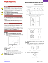
Figure
2-1.
Specifications
SECTION
3
-
INSTALLATION
3-1.
LOCATION
A
good
installation
is
essential
iftheweldingma
chine
is
to
provide
satisfactory
and
dependable
service.
Proper
component
operating
temperatures
are
maintained
by
the air
stream
produced
by
the
welding
machine
fan
unit.
The
welding
machine
should
be
located
so
that
the
air
passage
into
the
front
and
bottom
of
the
welding
machine
Is
not
re
stricted,
the
back
of
the
welding
machine
should be
away
from
the
wall
(18
inches
minimum
distance)
so
that
the
air
passagefromthefanwlllnot
be
blocked.
The
location
should
be
such
that
a
minimum
amount
of
dirt
or
dust
will
be
drawn
Into
the air
stream.
Preventive
maintenance
will
consist
of
re
WELDING
CURRENT
RANGE
AMPERES
RATED
WELDING
CURRENT
@32
VOLTS
60%
DUTY
CYCLE
OPEN
CIRCUIT
VOLTAGE
AC &
DC
POWER
INPUT
AT
RATED
LOAD
.
AC
AC
DC
DC
TUNGSTEN
METALLIC
TUNGSTEN
METALLIC
ARC
ARC
ARC
ARC
AMPERES
208
V
230V
460V
kw
kva
AMP
1-18
1-20 1-20
1-20
5-135
5-140
5-165
5-140
25-500
18-500
25-500
20435
300
Amperes
80
I
95
j
86
43
15
19.7
L
OM-342
Page
5

I
moving
the
cover
and
blowing
out
the
dust
ac
cumulation
inside
the
welding
machine.
For
this
reason
it
is
desirable
to
locate
the
unit
so
the
cover
can
be
removed
without
much
restriction.
~---
A
precautionary
measure
should
be
taken
to
provide
maximum
protection
against
electrical
shock.
When
electrical
connections
are
made
from
the
welding
machine
to
the
main
line
disconnect
switch.
Be
sure
the
line
disconnect
switch
has
been
opened
or
the
line
fuses
have
been
removed
and
remain
that
way
until
the
installation
has
been
completed.
I
I
EM
PORTANT1
High
frequency
has
certain
undersirable
char
acteristics
which
should
be
eliminated
or
at
least
minimized.
Any
electrical
equipment
utilizing
high
frequency
energy
in
any
way
is
capable
of
radiating
interference
if
not
properly
installed.
Since
the
High
Frequency
Unit
is
a
basic
type
of
radio
trans
mitter,
it
may
cause
interference
with
reception
of
of
nearby
radio
units.
Itis
recommended
that
maxi
mum
protection
be
provided
to
arrest
leakage
from
radiation.
I
3-2.
PRIMARY
CONNECTIONS
(Figure
3-2)
These
welding
machines
are
designed
to
operate
on
standard
voltage
of
either
208
volts,
230
volts
or
460
volts
single
phase,
60
Hz,
ac
power
line.
Facilities
for
operation
on
other
line
voltages,
if
ordered,
are
incorporated
at
the
factory.
To
con
nect
the
welding
machine
properly
for
the
voltage
available,
position
the
copper
links
located
im
mediately
above
the
primary
input
studs
labeled
L
or
LINE
as
illustratedinfigure32.
Welding
ma
chines
are
always
shippedwith
the
connections
in
the
highest
line
voltage
position
for
which
the
particular
machine
was
built
unless
otherwise
ordered.
If
there
is
any
question
about
the
type
of
the
system
used
locally,
or
the
proper
connections
to
obtain
single
phase
power
service
to
the
welding
machine,
consult
the
local
power
and
light
company.
Locate
and
open
the
access
door
below
the
fan
on
the
rear
panel
of
the
welding
machine.
The
primary
input
voltage
connections
terminal
board
is
behind
this
access
door.
The
welding
machine
must
operate
from
a
sep
arately
fused
or
circuit
breaker
protected
circuit.
The
maximum
capacity
of
the
welding
machine
Is
affected
by
the
line
voltage
and
if
the
circuit
is
Figure
3-1.
Dimensional
Drawing
AB-901
379-2
208/230/460
VOLTS
230/460/575
VOLTS
lii
a
FAN
MOTOR
ACROSS
z
Is-
a
W
s1
23OVOLTSINI/2K.V.A.
–
–
-J
FANMOTORACROSS
:
a-
I
I
HF.
ACROSS
988
FOWER
FACTOR
ACROSS
189
o
o
a
230
VOLTS
IN
1/2
K.V.A.
~
~
0
C
0
0
TIE
TOOETHER
364,
S&1O
~
1
6
3
6
2
POWER
FACTOR
ACROSS
189
HF.
ACROSS
687
1
7
2
6
8
3
SIMILAR
CONNECTEO
TIE
TOGETHER
264,
5610
VOLTAGES
SIMILAR
CONNECTEO
s
200/230/460
a
VOLTAGES
Is
230/460/480
51
230/460/500
2
3
6
7
6
9
LJk9rLib____
230/460/650
230/460/SI
0
230/460/520
208
VOLTS
230
VOLTS
460
VOLTS
230
VOLTS
460
VOLTS
575
VOLTS
I
a
~
I
I
~
~
~
~u~~nI
I
II
a
oW~t~
230/380/460
VOLTS
s-i
a
FANMOTORACROSS
,~
,,
Z
230
VOLTS
IN
1/2
K.V.A
FOWER
FACTOR
ACROSS
169
I
-i
-IF
ACROSS
669
C
a
a
C
0 0
TIE
TOGETHER
364,
5610
8
3
6
7
2
SIMILAR
CONNECTEO
VOLTAGES
L
L
230/415/460
15-
230/346/460
230/400/460
1
2
3
6
7
8
~
~
~
230
VOLTS
380
VOLTS
460
VOLTS
380
VOLTS
ONLY
SIMILAR
CONNECTEO
VOLTAGES
420
ONLY
419
ONLY
440
ONLY
400
ONLY
350
ONLY
TIE
364
TOGETHER
346
ONLY
TIE
9810
TOGETHER
TIE2&7
TOGETHER
CONNECT
iTO
LOAG
SlOE
OFCONTACTOR
1
CONNECT6TOL2STUD
I
HF
UNIT
ACROSS6&6
G
Li
L~
FFACROSS1&9
10
0
*
P
~~
II
II
I
1
'
14
66
Figure
3-2.
Primary
Line
Voltage
Connections
And
Link
Arrangement
AA-9G1
379-iO
Page
6

overloaded,
the
performance
of
thewelding
machine
will
be
impaired.
Install
separate
leads
or
cable
consisting
of
two
primary
leads
plus
one
ground
wire
(See
Table
3-1
for
proper
wire
and
fuse
size)
into
the
rear
of
the
welding
machine
near
the
bottom
through
the
inlet
hole
provided
for
this
purpose.
This
opening
will
take
standard
conduit
fittings
and
the
service
wires
from
the
line
disconnect switch
to
the
welding
ma
chine
should
be
run
in
solid
or
flexible
conduit.
If
flexible
conduit
Is
used,
Breeze
type
conduit
is
recommended
because
of
its
better
radio
frequency
shielding
characteristics.
TABLE
3-1.
Line
Voltage
Wire
And
Fuse
Sizes
PRIMARY
WIRE
SIZE
-
AWG
FUSE
SIZE
IN
AMPERES
208V
230V 460V
575~
150 150
70
601
I
MODEL
j~~p
208V
230V
460V
575V
No.6
No.6
No.8
No.8
(No.
6)
(No.
6)
(No.
8)
(No.
8)
The
primary
cables
connect
to
terminals
labeled
L
or
LINE.
A
third
lead,
ground
connection
should
be
fastened
to
the
terminal
labeled
GRD.
The
other
end
of
the
ground
lead
or
cable
should
be
attached
to
a
suitable
ground
such
as
a
water
pipe,
ground
rod
etc
Use
a
grounding
means
that
is
acceptable
to
the
local
electrical
inspection
author
ities.
3-3.
SECONDARY
CONNECTIONS
(Figure
3-3)
Open
the
front
access
door
and
notice
the
two
secondary
terminals
labeled
WORK
and
ELEC
TRODE.
It
is
recommended
that
the
welding
leads
be
kept
as
short
as
possible
to
prevent
high
frequency
dissipation
and
erratic
operation.
On
automatic
welding
operations
where
jigs
and
an
electrode
holder
carriage
may
be
used,
it
is
Important
that
all
metallic
parts
in
contact
with
the
work
be
firmly
grounded.
CAUTI0H
i
Be
sure
that
when
installing
the
welding
machine
that
a
ground
lead
is
connected
from
the
stud
labeled
GRD,
on
the
primary
connections
board,
to
a
suitable
ground.
This
Is
absolutely
necessary
as
any
development
of
stray
currents
may
give
a
severe
shock
should
anyone
touch
the
welding
machine
and
at
the
same
time
touch
any
grounded
object.
The
stud
labeled
GRD
is
connected
to
the
welding
machine
chassis
and
Is
for
grounding
purposes
only.
If
the
welding
machine
is
to
be
connected
to
one
phase
of
a
threephase
line.
Do
not
connect
the third
wire
from
a
three
phase
line
to
the
stud
labeled
GRD
as
this
may
result
In
a
hot
welding
machine
chassis.
Table
3-2
shows
the
welding
cables
sizes
recom
mended
for
various
total
welding
cable
lengths
and
currents.
These
figures
are
based
on
direct
current
and
a
4
volt
drop.
Use
next
larger
size
for
ac
weld
ing.
TABLE
3-2.
Cable
Size
For
Welding
Cable
Length
WELDING
AMPERES
TOT
AL
LENr
TH
OF
CABL.E
(COPPER
I
IN
WF
L.D
CIRCUIT
50
100
150
200 250
300 350
400
100
4
4
4
3
2
1
1/0
1/0
150
3
3
2
1
1/0
2/0
3/0
3/0
200
2
2
1
1/0
2/0
3/0 4/0
4/0
250
1
1
1/0
2/0
3/0
4/0
4/0
2.2/0
300
1/0 1/0
2/0
3/0
4/0
4/0
2.2/0
2-3/0
350
1/0
1/0
3/0 4/0
4/0
2.2/0
2-3/0 2.3/0
400
2/0
2/0
3/0 4/0
2-2/0
2.3/0 3-2/0
2.4/0
500
3/0
3/0
4/0
2-2/0
2.3/0
2-3/0 2-4/0
3.3/0
600
4/0
4/0
2-2/0 2-3/0
3.2/0
2-4/0
3-3/0
3.4/0
700
4/0
23/0
24~
3-3/0
34/0
44/0
44/0
Numbers
in
I
indicate
ground
wire
size
I
I
I
AB.901
379.6
Figure
3-3.
Primary
Connections
NOTE:
A.
B.
AA-900
56tJ
5OFEETOR
LESS
CABLE
SIZE
IS
BASED
ON
DIRECT
CURRENT
(DC(.
60%
DUTY
CYCLE
AND
EITHER
A
4
VOLTS
OR
LESS
DROP
OR
A
CURRENT
DENSITY
OF
NOT
OVER
300
CIRCULAR
MILS
PER
AMP.
C.
WELD
CABLE
INSULATION
WITH
A
VOLTAGE
RATING
TO
WITH
STAND
THE
OPEN
CIRCUIT
VOLTAGE
(O.C.V.)
OF
THE
WELD
ING
MACHINE
MUST
BE
USED.
WHILE
MOST
WELDING
MA
CHINES
HAVE
AN
OPEN
CIRCUIT
VOLTAGE
OF
LESS
THAN
100
VOLTS.
SOME
WELDING
MACHINES
OF
SPECIAL
DESIGN
MAY
HAVE
HIGHER
OPEN
CIRCUIT
VOLTAGE.
Figure
3-4.
Lower
Control
Panel
.AA.901
379-7
OM-342
Page
7

When
welding
with
ac
or
dc,
if
the
welding
cables
are
coiled
up
they
will
generate
a
magnetic
field
that
will
seriously
affect
the
operation
of
the
weld
ing
machine.
Always
lay
the
welding
cables
out.
Also,
the
welding
cables should
not
be
taped
to
gether,
when
using
high
frequency,
but
placed
about
3/4
inch
to
1
inch
apart
on
a
suitable
board
such
as
a
2
x
4,
1
x
4
or
1
x
6
and
fastened
with
plastic
clamps
or
clips.
Do
not
use
metal
clamps
as
they
will
tend
to
serve
as
an
antenna
and
radiate
high
frequency.
If
available,
the
use
of
vinyl
covered
cable
are
recommended
as
this
material
has
better
high
frequency
shielding
characteristics
than
rubber
covered
cable.
Bring
the
welding
cables
up
from
the
bottom
through
the
access
opening
and
connect
the
cable
from
the
material
to
be
welded
to
the
WORK
ter
minal.
Connect
the
electrode
holder
welding
cable
to
the
ELECTRODE
terminal.
3-4.
GAS
AND
WATER
CONNECTIONS
(Figure
3-4)
NOTE
Do
not
make
connections
to
the
water
valve
if
a
portable
water
coolant
system
is
used.
If
a
portable
water
coolant
system
is
used,
connections
should
be
made
directly
to
the
electrode
holder
water
connections,
by-passing
the
welding
ma
chines
water
valve.
-
-
The
water
valve
is
locatedontheleft
side,
behind
the
front
access
foor.
The
water
valve
adapter
con
nections
have
a
left
hand
5/8-18
female
thread.
Connect
the
hose
from
the
electrode
holder
labeled
WATER
IN
to
the
water
valve
connections
labeled
OUT.
The
gas
valve
Is
located-
on
the
right
side
behind
the
front
access
door.
Bring
the
gas
hose
up
through
the
access
opening
at
the
bottom
of
the
ma
chine
and
connect
to
the
gas
valve
connection
labeled
IN.
The
gas
connections
have
a
right
hand,
5/8-18
female
thread.
Make
sure
the
direction
of
gas
flow
through
the
valve
will
be
as
Indicated
on
the
panel.
Bring
the
electrode
holder
gas
hose
up
through
the
froM
access
opening
and
connect
the
the
gas
valve
connection
labeled
OUT.
The
gas
flow
must
be
controlled
accurately
with
the
aid
of
a
regulator
and
a
flow
meter.
No
specific
recommendations
for
rate
of
flow
can
be
given
as
this
depends
entirely
on
the
specific
welding
con
ditions.
Correct
argon
flow
is
usually
between
8
and
35
cubic
feet
of
gas
per
hour.
The
helium
flow
is
between,
18
and
35 cubic
feet
per
hour.
When
designing,
fixturing,
and
setting
up
welding
pro
cedures,
remember
the
specific
gravity
of
argon
is
heavier
than
air,
1.38
and
helium
is
lighter
than
air
.138w
air
being
1.
More
specific
information
concerning
the
process
to
satisfy
the
welding
needs
can
be
obtained
from
the
manufacturer
of
the
elec
trode
holder
equipment.
3-5.
REMOTE
WELD
AMPERAGE
CONTROL
CONNEC
TIONS
(Figure
3-4)
A
receptacle
(labeled
WELD
AMPERAGE
CON-
TROL)
is
provided
on
the
lower
control
panel
for
connecting
a
remote
amperage
control.
A
Model
RHC-3100
(Remote
Hand
Control),
BFC-3A-100,
RFC-23A-100
(Remote
Foot
Control)
or
FTC-3
100
(Finger
Tip
Control)
can
be
plugged
into this
receptacle
to
provide
remote
amperage
control.
Place
the
REMOTE-STANDARD
Switch,
located
immediately
below
the
Remote
Weld
Amperage
Control
Receptacle,
in
the
B
EMOTE
position
when
a
remote
control
is
used.
3-6.
REMOTE
CONTACTOR
CONTROL
CONNECTIONS
(Figure
3-4)
A
receptacle
(labeled
CONTACTOB
CONTROL)
is
provided
on
the
lower
control
panel
for
con
necting
a
maintained
contact
switch
(RHS-41,
RFS
4
or
RFC23A-100)
or
a
momentary
contact
nor
mally
open
switch
(RHS-4).
Connect
a
switch
to
this
receptacle
for
contactor
control
when
pro
cesses
other
than
Stick
Electrode
is
used.
3-7.
EMERGENCY
STOP
CONNECTIONS
(Figure
3-4)
Remove
the
jumper
link
from
terminals
1
and
2
TE2
(reading
left
to
right)
and
connect
a
normally
closed
switch
across
these
two
terminals
for
emergency
stop
control.
The
weld
sequence
can
be
interrupted
during
any
portion
of
the
sequence
when
the
machine
is
connected
and
all
controls
are
ad
justed
for
AUTO
TIG
welding.
If
the
Emergency
Stop
Switch
is
opened
during
the
sequence,
the
Post-
Flow
Timer
will
time
out
allowing
the
gas
and
water
-
to
cool
the
Electrode.
3-8.
WELD
HOLD
CONNECTIONS
(Figure
3-4)
The
purpose
of
these
terminal
strip
connections
is
to
provide
manual
control
of
the
weld
sequence.
With
the
jumper
link
removed
and
a
normally
open
switch
connected
to
these
terminals
continuous
welding
for
any
desired
length
of
time
can
be
had.
Remove
the
jumper
link
from
terminals
4
and
5
(reading
left
to
right)
and
connect
a
normally
open
set
of
contacts
or
switch
to
these
terminals.
At
the
end
of
the
desired
weld
time,
close
the
contacts
or
switch
to
initiate
downslope.
This
closed
set
of
con
tacts
or
closed
switch
must
remain
closed
until
after
Post
Flow.
3-9.
SIGNAL
TERMINAL
STRIP
(Figure
34)
CAUTION
I
There
is
115
volt
ac
potential
between
these
ter
minals
and
ground.
Make
no
connections
unless
power
is
removed
from
the
machine.
I
The
five
post
terminal
strip
located
directly
to
the
left
of
the
115
volt
ac
receptacle
has
terminal
connections
for
signaling
external
accessories
or
equipment
at
the
beginning
of
the
Preflow,
Upslope,
Downslope
or
Post-flow
Sequence.
Make
connections
to
the
terminals,reading
left
to
right,
as
follows:
Terminal
1
-
Common
Terminal
2
115
Volt
ac
Pre-Flow
Time
Signal
Terminal
3
115
Volt
ac
Upslope
and
Weld
Time
Signal
Terminal
4
-.
115
Volt
ac
Downslope
and
Final
Time
Signal
Terminal
5
-
115
Volt
ac
Post-Flow
Time
Signal
I
I
NOTE
I
I
I
I
I
Page
8

3-10.
115
VOLT
AC
RECEPTACLE
(Figure
3-4)
These
receptacles
are
connected
to
a
115
volt
ac
single
phase
power
source
Inside
the
welding
ma
chine,
and
is
provided
to
supply
operating
power
for
a
wire
feed
mechanism
or
a
carriage
motor
or
similar
equipment.
This
circuit
Is
fused
with
a
15
ampere
fuse.
Do
not
exceed
this
ampere
size.
Figure
3-5.
Control
Panel
View
AB.9O1 379-BA
I
NOTE
I
-
~--
Do
not
make
connections
tothesetermlnalsthatwill
draw
more
than
200
Milliamperes
per
terminal.
OM-342
Page
9

SECTION
4-.
OPERATION
CAUTION
I-
Never,
under
any
circumstances,
operate
the
weld
ing
machine
with
the
cover
or
sides
removed.
In
addition
to
the
safety
hazard,
improper
cooling
may
result
in
damage
to
the
power
transformer
and
weld
ing
machine
components.
Warranty
is
void
if
the
machine
is
operated
with
the
cover
or
sides
re
moved.
4-1.
DUTY
CYCLE
(Figure
4-1)
Welding
machines
are
rated
on
a
percent
duty
cycle
based
on
,10
minute
intervals.
For
example:
A
60
%
duty
cycle
simply
means
that
the
welding
current
is
on
for
6
minutes,off
4
minutes,
on
again
for
6
minutes
and
so
on.
As
the
output
is
either
in
creased
or
decreased,
the
duty
cycle
will
increase
or
decrease.
It
must
be
kept
in
mind
that
time
intervals
other
than
10
minutes
will
yield
different
test
rating
results.
400
4-2.
VOLT-AMPERE
CURVES
(Figure
4-2)
The
voltampere
curves
show
the
output
voltage
available
at
any
given
output
current
within
the
limits
of
the
minimum
and
maximum
Fine
Current
Ad
justment
Control
setting.
Load
voltage
is
predeter
mined
to
a
large
degree
by
arc
characteristics.
With
the
use
of
the
voltampere
curves,
it
is
possible
to
determine
the
amperage
required
for
a
particular
load
voltage.
With
reference
to
the
volt-ampere
curves,
the
curves
show
the
maximum
and
minimum
settings
of
the
Fine
Current
Adjustment
Control
only.
Curves
for
other
settings
will
fall,
between
the
maximum
and
minimum
curves
shown.
4-3.
WELDING
AMPERAGE
CONTROL
Select
the
welding
current
range
desired,
by
ad
justing
the
Current
Range
Selector
Switch
to
one
of
the
three
current
positions.
Current
ranges
shown
are
Gas
TungstenArc
Ratings.
Amperage
output
will
be
somewhat
lower
for
dc
Shielded
Metal-Arc
(Stick
Electrode)
Welding
than
that
shown.
I
I
IMPORTANT
Do
not
operate
the
Current
Range
Switch
or
the
ad
dc
Selector
and
Polarity
Switch
under
load.
Arcing
caused
by
opening
the
switch
carrying
high
current
will
severely
burn
the
contact
surfaces
of
the
switch.
This
burning
of
the
contact
surfaces
will
decrease
the
maximum
current
carrying
capacity
of
the
switch
and
possibly
cause
the
switch
to
become
inoperative.
A
three
position
Selector
and
Polarity
Switch
per
mits
the
welding
machine
to
select
ac,
dc
STRAIGHT
or
dc
REVERSE
Polarity.
Place
the
switch
in
the
proper
position
required
for
the
welding
application.
Fine
current
adjustments
of
the
current
range
set
tings
of
the
CURRENT
RANGE
Switchisobtainedby
the
Weld
Current
Control
on
the
SCM
panel.
4-4.
REMOTE
WELD
AMPERAGE
CONTROL
(Optional)
A
Remote
Weld
Amperage
Control
Receptacle
is
provided
for
connecting
a
(RHC-3-100)
Remote
Hand
Control
or
a
(RFC-3A-100)
Remote
Foot
Con
trol
or
any
other
suitable
remote
controls
(See
Optional
Equipment.
The
Remote
Amperage
Control
Receptacle
is
located
on
the
upper
left
side
of
the
lower
control
panel.
A
switch
labeled
STANDARD-
REMOTE
is
located
immediately
above
the
re
ceptacle
and
must
be
placed
in
the
REMOTE
position
when
a
remote
amperage
control
is
used.
The
control
circuit
is
designed
so
that
the
Weld
Current
Adjustment
Control
on
the
welding
machine
will
indicate
only
the
maximum,
welding
output
of
each
current
range,
when
the
remote
control
unit
is
used.
Control
from
maximum
to
minimum
is
ac
350
300
C
0
z
C
250
200
30 35
40
50
60 70
80
%
DUTY
CYCLE
Figure
4-1.
Duty
Cycle
Chart
06-901
161-IA
90
100
80
70
60
,-
.J
0
50
>
u
40
C
30
20
a
,-
a
0
~1
0
100
200
300
400
500
600
700
0
AC
AMPERES
66-901
161-1
Figure
4-2.
Volt-Ampere
Curves
100
200
300
400
500 600 700
DC
AMPERES
66-901
161-2
Page
10
/