Page is loading ...

M
S
P
CEILING JOIST
SOLIVES DE
PLAFOND
2 X 4
1B
N
D
L
A
C
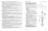
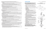
MOUNTING TO A STANDARD OUTLET BOX
MEANS OF SUPPORT MUST BE ERECTED ABOVE OUTLET BOX. BELOW IS ONE SUG-
GESTED METHOD.
1) Screw threaded rod (P) from parts bag into pipe coupling (A) until
threaded pipe is flush with top of pipe coupling. Secure in place by
tightening allen head screw (C) with provided wrench.
2) Slip mounting strap (D) over provided 1/2-13UNC threaded rod (P).
3) Remove knockout in top of outlet box.
4) Support cable from fixture (see sec. 3) must pass through outlet box.
Drill 3/16” diameter hole in outlet box if no other holes are available.
5) In area above outlet box pass threaded rod (P) through hole in center
of outlet box.
6) Lay a 2x4 across ceiling joist on either side of threaded rod (P).
7) Secure 2x4’s in place by toe-nailing or other means.
8) Screw hexnut (H) onto threaded rod (P).
9) Slip ground lug (F) and lockwasher (J) onto threaded rod (p).
10) Thread screw collar loop (L) onto threaded rod (P) until threaded pipe
is flush with hole on lower side of screw collar loop.
11) Secure screw collar loop (L) in place by tightening hexnut (H) down
against ground lug (F), lockwasher (J) and screw collar loop.
12) Temporarily slip canopy (M) over screw collar loop (L). Approximately
one half of the screw collar loop exterior threads should be exposed
below canopy.
13) Temporarily screw threaded ring (N) onto screw collar loop (L).
14) In area above outlet box pull up on threaded rod (P) until canopy is
snug against ceiling.
15) Slide mounting strap (D) down threaded rod (P) and against 2x4’s.
16) Screw pipe coupling (A) down threaded rod (P) until pipe coupling is
snug against mounting strap (D) and canopy (M) is snug against ceiling.
17) Tighten allen head screw (C).
18) Secure mounting strap (D) in place by laying diagonally across both
2x4’s and driving two #10 x 1" sheet metal or equivalent screws
(not provided) through holes at ends of mounting strap. Tighten anti-
rotational hex screw located next to center hole inside mounting strap (D)
with provided allen wrench..
NOTE: Mounting strap (D) must be secured to prevent rotation.
19) Remove threaded ring (N) and canopy (M).
MONTAGE À UNE BOÎTE À PRISES STANDARD
LES MOYENS DE SUPPORT DOIVENT INSTALLÉS AU-DESSUS DE
LA BOÎTE À PRISES. MÉTHODE SUGGÉRÉE
1) Visser la tige filetée (P) qui se trouve dans le sac à pièces sur
l'accouplement du tube (A) jusqu'à ce que la tige filetée soit
alignée avec la partie supérieure de l'accouplement du tube.
Bloquer en serrant les vis Allen (C) avec la clé fournie.
2) Passer le support de montage (D) sur la tige filetée (P) de
1/2-13UNC.
3) Enlever l'alvéole défonçable en haut de la boîte à prises.
4) Le câble de support du luminaire (voir la section 3) doit passer
par la boîte à prises. Percer un trou de 3/16 po de diamètre
dans la boîte à prises si aucun autre trou n'est disponible.
5) Au-dessus de la boîte à prises, passer la tige filetée (P) par le trou au centre de la boîte à
prises.
6) Placer une colombe deux par quatre à travers les solives de plafond de chaque côté de la tige
filetée (P).
7) Fixer bien les colombes en les clouant en biais ou par d'autres moyens.
8) Visser l’écrou hexagonal (H) sur la tige filetée (P).
9) Passer la cosse de masse (F) et la rondelle de blocage (J) sur la tige filetée (P).
10) Visser la boucle à vis (L) sur la tige filetée (P) jusqu'à ce que le tube fileté s'aligne avec le trou
du côté inférieur de la boucle à vis.
11) Fixer la boucle à vis (L) en serrant l'écrou hexagonal (H) contre la cosse de masse (F) et la
rondelle de blocage (J) et la boucle à vis.
12) Passer temporairement le cache (M) sur la boucle à vis (L). La moitié du filetage extérieur de
la boucle à vis doit être visible sous le cache.
13) Visser temporairement la bague filetée (N) sur la boucle à vis (L).
14) Au-dessus de la boîte à prises, tirer sur la tige filetée (P) jusqu'à ce que le cache soit bien
serré contre le plafond.
15) Faire glisser en aval le support de montage (D) le long de la tige filetée contre la partie
supérieure des colombes.
16) Visser l'accouplement du tube (A) sur la tige filetée (P) jusqu'à ce que l'accouplement du tube
soit bien contre le support de montage (D) et que le cache (M) se trouve contre le plafond.
17) Resserrer la vis allen (C).
18) Fixer le support de montage (D) en plaçant diagonalement les deux
colombes deux par quatre et en vissant deux vis à tôle No 10 x 1 po ou des vis équivalentes
(non fournies) par les trous aux extrémités du support de montage. Resserrer les écrous
hexagonaux anti-rotation situés près du trou central à l'intérieur du support de montage (D)
avec la clé allen fournie.
REMARQUE: le support de montage (D) doit être bien fixé pour empêcher toute rotation.
19) Enlever l’anneau fileté (N) puis le cache (M).
F
J
H
FIXTURE ASSEMBLY
For ease in assembly, proceed to section 3. Remaining steps in fixture
assembly can be completed easier with fixture hanging.
1) Slip glass over socket at end of arm and secure in place
with socket ring. (DO NOT over tighten.)
MONTAGE DU LUMINAIRE
Pour faciliter le montage, passer à la section 3.
Les dernières étapes du montage du luminaire peuvent être
exécutées plus facilement avec le luminaire suspendu.
1) Passer le verre par-dessus la douille à l’extrémité du bras et fixer
à l’aide de l’anneau de la douille. (NE PAS serrer avec excès.)
2
LOOP
ANNEAU
GLASS
VERRE
SOCKET RING
ANNEAU DE
DOUILLE
SOCKET
DOUILLE
ARM
BRAS
IS-1675-CB
/


