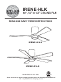
Atlas IR3HLK-BK-WA-42 Operating instructions
- Category
- Household fans
- Type
- Operating instructions
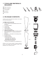
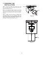
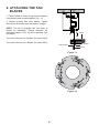
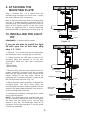
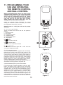
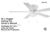
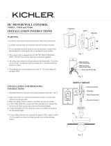
Atlas IR3HLK-BK-WA-42 is a ceiling fan designed for indoor use with a variety of features to enhance comfort and convenience. It comes with a handheld remote control, a wall-mounted control, and a light kit with an LED bulb, giving you multiple options for controlling the fan's speed, direction, and lighting. The fan has three reversible blades, allowing you to customize the airflow direction for your needs, and it can be mounted on ceilings with a minimum clearance of 7 feet from the floor to the trailing edge of the blades.
Atlas IR3HLK-BK-WA-42 is a ceiling fan designed for indoor use with a variety of features to enhance comfort and convenience. It comes with a handheld remote control, a wall-mounted control, and a light kit with an LED bulb, giving you multiple options for controlling the fan's speed, direction, and lighting. The fan has three reversible blades, allowing you to customize the airflow direction for your needs, and it can be mounted on ceilings with a minimum clearance of 7 feet from the floor to the trailing edge of the blades.


-
 1
1
-
 2
2
-
 3
3
-
 4
4
-
 5
5
-
 6
6
-
 7
7
-
 8
8
-
 9
9
-
 10
10
-
 11
11
-
 12
12
-
 13
13
-
 14
14
-
 15
15


Atlas IR3HLK-BK-WA-42 Operating instructions
- Category
- Household fans
- Type
- Operating instructions
Atlas IR3HLK-BK-WA-42 is a ceiling fan designed for indoor use with a variety of features to enhance comfort and convenience. It comes with a handheld remote control, a wall-mounted control, and a light kit with an LED bulb, giving you multiple options for controlling the fan's speed, direction, and lighting. The fan has three reversible blades, allowing you to customize the airflow direction for your needs, and it can be mounted on ceilings with a minimum clearance of 7 feet from the floor to the trailing edge of the blades.
Ask a question and I''ll find the answer in the document
Finding information in a document is now easier with AI
Related papers
-
Atlas IR5H-WH-BW-60 Operating instructions
-
Atlas KC-BN Installation guide
-
Atlas IR5HLK-BK-BW-42 Operating instructions
-
Atlas IR5-TB-BW-42 Operating instructions
-
Atlas IR3HLK-TB-WA-42 Operating instructions
-
-
Atlas IR5H-BRBR-BW-42 Operating instructions
-
Atlas IR3H-WH-BW-42 Operating instructions
-
Atlas DGLK-TB-WD Operating instructions
-
Other documents
-
 Hampton Bay AL383-WH User guide
-
WINGBO WBCF-Q008-NI User manual
-
 Kichler Lighting 370036ALMTR User manual
-
 Greenstone MFS35PG Installation guide
-
Matthews Fan Company BIANCA DIRECIONAL Series Installation Instructions Manual
-
Merra CFN-1105 User manual
-
Merra CFN-1101 User manual
-
Canarm IPL586A03ORB Operating instructions
-
 Hampton Bay 9050H Operating instructions
-
 Lavish Home HW720000 User manual


