
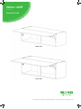
WALL UNIT
1000 Lift
Assembly Guide
For Internal Use: FI.WR.INS.033_WKIN00122_WALL_1000_Lift_Extractor_Housing_Rev5.indd
288 x 1000
360 x 1000

WALL UNIT
1000 Lift
Assembly Guide
For Internal Use: FI.WR.INS.033_WKIN00122_WALL_1000_Lift_Extractor_Housing_Rev5.indd
Page 1
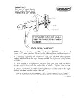
BEFORE YOU START
INSTALLATION
SHOULD BE
PERFORMED BY A
COMPETENT
PERSON ONLY.
THIS PRODUCT COULD
BE DANGEROUS
IF INCORRECTLY
INSTALLED
Panel A
x1 Back Panel
HANGING BRACKET
x2 Inc Screws
(F) x8
Wooden Dowel
REQUIRED TOOLS
NOT to be used
with CAM DOWEL
& CAM LOCK
(G) x8
Cam Dowel
(Expanding)
(H) x8
Cam Lock
(K) x4
30mm
Screw
(L) x8
15mm
Screw
(S) x4
20mm
Screw
(M) x8
Cover Cap
(N) x1
Door
Buer
(T) x10
Back Panel
Support Clip
HANGING BRACKET PLATE
x2 (Screws NOT included)
HINGE MOUNTNG
PLATE x2 Inc Screws
HINGE
x2 Inc Screws
CORNER
GUSSET
x2
HANGING BRACKET
COVER CAP
x2
LIFT HINGE
x2 Inc Screws
Panel B
x2 End Panel
Panel C
x2 Base Panel
Frontal
(packed separately)
x1
Muntin
x1

WALL UNIT
1000 Lift
Assembly Guide
For Internal Use: FI.WR.INS.033_WKIN00122_WALL_1000_Lift_Extractor_Housing_Rev5.indd
Page 2
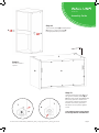
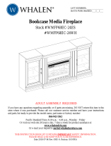
Dowel (F)
& Cam Dowel (G)
location detail
G
G
F
F
F
F
G
G
B
Step 1.
Seat dowel
(F) into holes in
end panel (B) as
shown.
Step 2.
Seat cam dowel
(G) into holes in
end panel (B) as
Step 3.
Attach panels x2 (C) to panel
(B), using cam dowels (G)
& cam locks (H) (in blue),
and also using dowels (F)
(in orange) in positions as
shown.
Step 4.
Slide panel (A) into the groove
of panels (B) and x 2 (C).
Step 5.
Insert cam lock (H).
Hand tighten all
cam locks (H), this
will expand the cam dowels
(G) and tighten the unit
together.
All Cam Locks (H) are to be positioned facing the
outside of the unit carcass, for ease of tightening.
Do not use power tools with
cam dowel (G) or cam lock (H)
B
A
C
C
B
C
C
H
H
G
G
View from undersideView from underside
Seat (G)
cam dowel
into hole as
shown.

WALL UNIT
1000 Lift
Assembly Guide
For Internal Use: FI.WR.INS.033_WKIN00122_WALL_1000_Lift_Extractor_Housing_Rev5.indd
Page 3
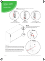
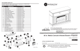
Step 6.
Seat dowel
(F) into holes in
both panels (B)
as shown.
Step 7.
Seat cam dowel
(G) into holes in
both end panels (B)
as shown.
Step 8.
Attach panel (B) to panels
(C) using cam dowels (G)
& cam lock (H) (in blue)
and also using dowels (F)
(in orange) in positions as
shown. Ensure panel (A) is
seated into the groove of
panel (B).
Step 9.
Insert cam lock (H).
Hand tighten all
cam locks (H), this will
expand the
cam dowels (G) and tighten
the unit together.
All Cam Locks (H) are to be positioned facing the
outside of the unit carcass, for ease of tightening.
Do not use power tools with
cam dowel (G) or cam lock (H)
B
B
A
C
H
H
C
B
C
C
H
H
G
G
View from undersideView from underside
Dowel (F)
& Cam Dowel (G)
location detail
G
G
F
F
F
F
G
G
B
Seat (G)
cam dowel
into hole as
shown.

WALL UNIT
1000 Lift
Assembly Guide
For Internal Use: FI.WR.INS.033_WKIN00122_WALL_1000_Lift_Extractor_Housing_Rev5.indd
Page 4
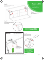
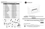
Step 12.
Slide the back panel clips (T) into
the groove of both panels (B) &
(C). The back panel clips (T) should
be evenly spaced as shown and
positioned to allow the hanging
bracket and corner gussets to
be tted. Once in place, tighten
screw.
The side back panel Clips should
be disregarded for the 288 units.
Step 10.
Join muntin panel (D) to both panels
(C) using 4 x 45mm screws (P),
through pilot holes provided.
Step 11.
Ensure carcass is
square.
B A
C
P
P
A
T
A
T

WALL UNIT
1000 Lift
Assembly Guide
For Internal Use: FI.WR.INS.033_WKIN00122_WALL_1000_Lift_Extractor_Housing_Rev5.indd
Page 5
Step a
Insert Hanging
Bracket into pre-drilled holes
Step c
Secure with provided
2 x 20mm screws (S) per bracket
Step b
Rotate locking
lever 180 degrees
S
S
Detail A
Detail A
Detail A
Step 13. Hanging Brackets steps a,b & c to be carried
out on both sides as shown
A
B
Step 14.
Secure corner gussets to the bottom left and
right hand side of the wall unit using
4 x 15mm screws (L) per plate.
L
L
L
L
Detail B
View though
Back Panel
Pilot
hole
M
Detail B
Step 15.
Drill a small pilot hole through the centre of the Corner Gussets.
Use this hole at the end of the process to screw through and
into the wall. Cover the screw heads using the cover caps (M)
provided.
Screws for xing to walls are not provided as these vary
depending on your wall material and construction. Ensure
appropriate xings for wall constructions are used.

WALL UNIT
1000 Lift
Assembly Guide
For Internal Use: FI.WR.INS.033_WKIN00122_WALL_1000_Lift_Extractor_Housing_Rev5.indd
Page 6
Step 16.
Measure and attach Hinge Mounting Plate onto xed shelf (C) as shown,
using screws which are already positioned within the Hinge Plates.
Hinge Plates
Front Front
37 37
Left Right94 94126 126
C
TOP FIXED SHELF
192 192
160 160
Top
Top
Front
Front
37 37
LEFT HAND RIGHT HAND
B B
Step 17.
Measure and attach lift hinge
bracket with 2 x screw per bracket.
The required screws are included
inside lift hinge pack.
Removed from lift hinge
B
B
C
Step 18.
Measure and attach lift hinge bracket to frontal with 2 x screw per
bracket. The required screws are included inside lift hinge pack.
142142
110 110
Back
Back
Left
Right
30
30
FRONTAL
Step 20.
Secure hinges by tightening
2 x screws with plastic grommet
attached. These are already
positioned within the hinges.
Step 19.
Insert hinges into holes provided.

WALL UNIT
1000 Lift
Assembly Guide
For Internal Use: FI.WR.INS.033_WKIN00122_WALL_1000_Lift_Extractor_Housing_Rev5.indd
Page 7
Step 21.
Measure appropriately and attach the 2 x hanging bracket plates onto the
wall screwing through the provided holes into your wall.
Screws for xing to walls are not provided as these vary depending
on your wall material and construction. Ensure appropriate xings for
wall construction are used.
Hanging Bracket
Plate
Step 22.
Hang the cabinet using
the brackets to hook
onto the plate as shown
Step 23.
Using points a, b & c adjust the Cabinet to suit.
Step a.
Rotate the screw clockwise
to move the cabinet up.
Anti-clockwise for down.
Step c.
Screw the red screw until it
touches the plate to lock
in position.
b
c
a
Step 24.
Screw into any side units using the
provided 2x 30mm screws (K) to
secure the unit. Screw just to the
rear of the hinge plate then place a
cover cap on the head to conceal it.
Hanging
Bracket
viewed though
Back Panel
C
a
b
Step b.
Adjust the depth
using centre
screw.
K
Care to be taken. Hanging procedure
is neccesary for a safe installation.

WALL UNIT
1000 Lift
Assembly Guide
For Internal Use: FI.WR.INS.033_WKIN00122_WALL_1000_Lift_Extractor_Housing_Rev5.indd
Page 8
Step 25.
Clip hinges into hinge mounting
plates on the unit.
Step 26.
Clip lift hinge mechanisms
into each bracket.
Step 27.
Use a 4mm allen key to adjust
the strength of the lift hinge for
the door weight.
Step 28.
Fit cover caps to hinge.
Adjust Softclose to suit.
To adjust hinge using a screw
driver, tighten or loosen as
required at points 1 & 2.
Point 1 - In - Out
Point 2 - Left - Right
1
2
FRONTAL HINGE
ADJUSTMENT
View from Inside of Carcase
To release door,
pull catch as shown,
to release hinge from
the hinge plate.
The top and bottom
hinges MUST be
adjusted to the SAME
STRENGTH.
Hinge Cover Caps
The left and right hinges MUST be
adjusted to the SAME STRENGTH.

WALL UNIT
1000 Lift
Assembly Guide

WALL UNIT
1000 Lift
Assembly Guide

-
 1
1
-
 2
2
-
 3
3
-
 4
4
-
 5
5
-
 6
6
-
 7
7
-
 8
8
-
 9
9
-
 10
10
-
 11
11
-
 12
12


Wren Kitchens WALL UNIT 288 x 1000 Assembly Guide
- Type
- Assembly Guide
- This manual is also suitable for
Ask a question and I''ll find the answer in the document
Finding information in a document is now easier with AI
Related papers
-
Wren 1000mm Tall Wall Unit Assembly Manual
-
Wren Kitchens 1000mm Wall Unit Assembly Guide
-
-
-
-
-
-
-
-
Other documents
-
-
-
 Sandusky VFC1301566-05 Operating instructions
-
-
-
B&Q WALL Assembly Manual
-
 ClosetMaid MasterSuite Installer's Assembly, Installation & Reference Manual
-
 Whalen WMFP68EC-24WH User manual
-
 Whalen WSLWFP48-5/1031289 User manual
-
 Whalen WSLWFP54-6 User manual


