Bacharach ECA 450 User manual
- Category
- Measuring, testing & control
- Type
- User manual
This manual is also suitable for

Environmental Combustion Analyzer
Model 450
Instruction 0024-9400
Operation & Maintenance
Rev. 7 – October 2014
Product Leadership • Training • Service • Reliability

ii Instruction 0024-9400
WARRANTY
Bacharach, Inc. warrants to Buyer that at the time of delivery this Product will be free from defects in material and
manufacture and will conform substantially to Bacharach Inc.’s applicable specifications. Bacharach’s liability and
Buyer’s remedy under this warranty are limited to the repair or replacement, at Bacharach’s option, of this Product or
parts thereof returned to Seller at the factory of manufacture and shown to Bacharach Inc.’s reasonable satisfaction to
have been defective; provided that written notice of the defect shall have been given by Buyer to Bacharach Inc. within
one (1) year after the date of delivery of this Product by Bacharach, Inc.
Bacharach, Inc. warrants to Buyer that it will convey good title to this Product. Bacharach’s liability and Buyer’s
remedy under this warranty of title are limited to the removal of any title defects or, at the election of Bacharach, to
the replacement of this Product or parts thereof that are defective in title.
THE FOREGOING WARRANTIES ARE EXCLUSIVE AND ARE GIVEN AND ACCEPTED IN LIEU OF (I) ANY AND
ALL OTHER WARRANTIES, EXPRESS OR IMPLIED, INCLUDING WITHOUT LIMITATION THE IMPLIED
WARRANTIES OF MERCHANTABILITY AND FITNESS FOR A PARTICULAR PURPOSE: AND (II) ANY OBLIGA-
TION, LIABILITY, RIGHT, CLAIM OR REMEDY IN CONTRACT OR TORT, WHETHER OR NOT ARISING FROM
BACHARACH’S NEGLIGENCE, ACTUAL OR IMPLIED. The remedies of the Buyer shall be limited to those provided
herein to the exclusion of any and all other remedies including, without limitation incidental or consequential
damages. No agreement varying or extending the foregoing warranties, remedies or this limitation will be binding
upon Bacharach, Inc. unless in writing, signed by a duly authorized officer of Bacharach.
Note: The probe is considered a consumable item and is therefore not covered under the terms of this warranty.
HAZARDOUS AREA WARNING:
This instrument has not been designed to be intrinsically
safe for use in areas classified as hazardous locations. For your safety,
DO NOT
use it in
hazardous (classified) locations.
COMBUSTIBLE/FLAMMABLE GAS WARNING: This is NOT a safety device. Some flue
gases which this instrument can measure may be combustible/flammable. This instrument
should not be used to monitor combustible flue gases at or above their respective lower
explosive limits (LEL). Immediately correct those conditions in the appliance (e.g. boiler,
furnace…) causing unfired combustible gases before proceeding with the flue gas
measurements.
Register Your Warranty By Visiting
www.mybacharach.com
Notice:
Product improvements and enhancements are continuous, therefore the specifications and information
contained in this document may change without notice.
Bacharach, Inc. shall not be liable for errors contained herein or for incidental or consequential damages
in connection with the furnishing, performance, or use of this material.
No part of this document may be photocopied, reproduced, or translated to another language without the
prior written consent of Bacharach, Inc.
Copyright © 2000−2014, Bacharach, Inc., all rights reserved.
BACHARACH® is a registered trademark of Bacharach, Inc. All other trademarks, trade names,
service marks and logos referenced herein belong to their respective owners.

ECA 450 Contents
Instruction 0024-9400 iii
Table of Contents
1 Introduction .................................................................................................................... 1
1.1 General Description ................................................................................................................................... 1
1.2 Features ..................................................................................................................................................... 1
1.3 Technical Data ............................................................................................................................................ 2
1.4 Operation Overview ................................................................................................................................... 5
1.5 Front Panel Connections and Controls ...................................................................................................... 6
1.5.1 GAS, PRESSURE, T-STACK (Probe) .............................................................................................. 6
1.5.2 T-AIR (Primary Air Thermocouple) ............................................................................................. 7
1.5.3 POWER (AC Adapter) ................................................................................................................. 7
1.5.4 ∆P REF (Differential Pressure) ................................................................................................... 7
1.5.5 RS232 (Computer Interface) ...................................................................................................... 7
1.5.6 OPT (Option) .............................................................................................................................. 7
1.6 Front Panel Keypad Controls ..................................................................................................................... 8
2 Operation ..................................................................................................................... 11
2.1 Turning On the Analyzer .......................................................................................................................... 11
2.2 Turning Off the Analyzer .......................................................................................................................... 11
2.3 Fuel Selection ........................................................................................................................................... 12
2.4 Performing a Combustion Test ................................................................................................................ 13
2.5 Ending a Combustion Test ....................................................................................................................... 15
2.6 Performing a Draft Measurement ........................................................................................................... 15
2.7 Saving Test Data ....................................................................................................................................... 16
2.8 Clearing Memory ..................................................................................................................................... 16
2.9 Recalling Test Data Stored in Memory ..................................................................................................... 17
2.10 Printing Data ............................................................................................................................................ 19
2.11 Downloading Data to a Personal Computer ............................................................................................ 20
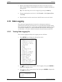
2.12 Data Logging ............................................................................................................................................ 22
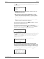
2.12.1 Turning Data Logging On .......................................................................................................... 22
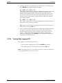
2.12.2 Turning Data Logging Off ......................................................................................................... 24
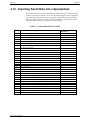
2.13 Importing Saved Data Into a Spreadsheet ............................................................................................... 25
2.14 Primary Air Temperature Measurement ................................................................................................. 27
2.14.1 Thermocouple Method ............................................................................................................ 27
2.14.2 Probe Thermocouple Method ................................................................................................. 27
2.14.3 Thermometer Method ............................................................................................................. 29
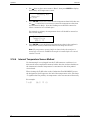
2.14.4 Internal Temperature Sensor Method ..................................................................................... 30
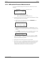
2.15 Differential Pressure Measurement ........................................................................................................ 31
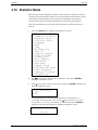
2.16 Statistics Mode......................................................................................................................................... 32
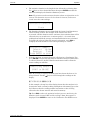
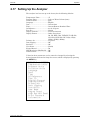
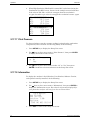
2.17 Setting Up the Analyzer ........................................................................................................................... 35
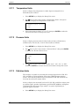
2.17.1 Temperature Units ................................................................................................................... 36
2.17.2 Pressure Units .......................................................................................................................... 36
2.17.3 Pollution Units ......................................................................................................................... 36
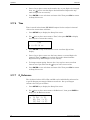
2.17.4 Language .................................................................................................................................. 37
2.17.5 Date .......................................................................................................................................... 37
2.17.6 Time ......................................................................................................................................... 38
2.17.7 O
2
Reference ............................................................................................................................ 38
2.17.8 Test ID ...................................................................................................................................... 39
2.17.8.1 Enter / Edit Test ID Information ......................................................................... 39
2.17.8.2 Select Test ID ...................................................................................................... 40
2.17.8.3 Transmit Test ID.................................................................................................. 41
2.17.8.4 Clearing Test ID Information .............................................................................. 42
2.17.9 Display Timeout ....................................................................................................................... 43
2.17.10 Display Format ......................................................................................................................... 43
2.17.10.1 Changing Display Format .................................................................................... 44

Contents ECA 450
iv Instruction 0024-9400
2.17.10.2 Resetting Display Format Back to Factory Default ............................................. 44
2.17.11 Primary Air ............................................................................................................................... 45
2.17.12 Data Logging ............................................................................................................................ 45
2.17.13 Statistics ................................................................................................................................... 45
2.17.14 User Name ............................................................................................................................... 45
2.17.14.1 Enter / Edit User Name Information................................................................... 45
2.17.14.2 Clear User Name Information............................................................................. 46
2.17.15 Keypad Sound .......................................................................................................................... 46
2.17.16 High Resolution NOx Enable .................................................................................................... 47
2.17.17 Print Pressure ........................................................................................................................... 48
2.17.18 Information .............................................................................................................................. 48
3 Calibration .................................................................................................................... 49
3.1 Initial Sensor Check .................................................................................................................................. 49
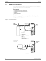
3.2 Calibration Fixtures .................................................................................................................................. 50
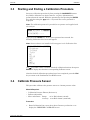
3.3 Starting and Ending a Calibration Procedure ........................................................................................... 51
3.4 Calibrate Pressure Sensor ........................................................................................................................ 51
3.5 Calibrate T-Stack (Stack Temperature) Channel ...................................................................................... 52
3.6 Calibrate T-Air (Ambient Temperature) Channel ..................................................................................... 53
3.7 Calibrate HC Sensor ................................................................................................................................. 54
3.8 Calibrate CO-LO Sensor ............................................................................................................................ 55
3.9 Calibrate SO
2
Sensor ................................................................................................................................ 57
3.10 Calibrate NO Sensor ................................................................................................................................. 58
3.11 Calibrate NO
2
Sensor ................................................................................................................................ 59
3.12 Calibrate CO-HI Sensor ............................................................................................................................. 60
4 Maintenance ................................................................................................................. 61
4.1 Battery Charging ...................................................................................................................................... 61
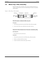
4.2 Water-Trap / Filter Assembly ................................................................................................................... 62
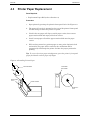
4.3 Printer Paper Replacement ...................................................................................................................... 63
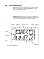
4.4 Sensor Replacement ................................................................................................................................ 64
4.4.1 O
2
, CO, NO, NO
2
, & SO
2
Sensor Replacement .......................................................................... 65
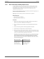
4.4.2 Nitric Oxide Sensor Battery Replacement ................................................................................ 66
4.4.3 HC Sensor Replacement ........................................................................................................... 67
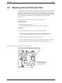
4.5 Replacing Internal Particulate Filter ......................................................................................................... 68
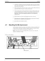
4.6 Cleaning the Probe and Sampling Hoses ................................................................................................. 69
4.7 Resetting the Microprocessor .................................................................................................................. 70
5 Troubleshooting ............................................................................................................ 72
5.1 Analyzer Repair ........................................................................................................................................ 72
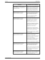
5.2 Problem Messages Displayed After Warm-Up ......................................................................................... 72
5.3 Error Symbols ........................................................................................................................................... 73
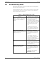
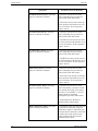
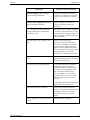
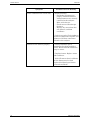
5.4 Troubleshooting Guide ............................................................................................................................ 74
6 Parts & Service .............................................................................................................. 79
6.1 Replacement Parts ................................................................................................................................... 79
6.2 Accessories ............................................................................................................................................... 80
6.3 Service Centers ........................................................................................................................................ 81

ECA 450 Introduction
Instruction 0024-9400
1
1 Introduction
1.1 General Description
The Bacharach Environmental Combustion Analyzer Model 450 (hereafter
referred to as the ECA 450) is an industrial grade environmental and
combustion efficiency analyzer that is designed for the testing of fuel-burning
combustion equipment. This analyzer is for furnace and boiler technicians
who need to determine combustion safety, environmental compliance, and
efficiency of small to large commercial industrial heating systems.
1.2 Features
• Measures and displays O
2
and CO in the flue gas, pressure (draft),
primary air temperature, and stack temperature.
• Calculates combustion efficiency, excess air, and CO
2
.
• Optionally measures and displays NO, NO
2
, SO
2
, HC (methane equivalent
combustibles), and CO (in the high range of 4,000 to 80,000 ppm).
• Optionally calculates NOx (the combination of NO and NO
2
), and
calculates CO, SO
2
, and NOx individually referenced to a user defined
Oxygen level of between 0 and 15%.
• Automatically purges the low-range CO sensor with fresh air if the CO
level exceeds 4,000 ppm. At this time the analyzer also automatically
switches over to its optional high-range CO sensor, if installed.
• Automatically zeros all sensing channels on ambient air when the
analyzer is first turned on.
• Displays temperature in either °C or °F.
• Displays pressure in either inches of water column (inwc), millibars (mb),
Pascals (Pa), or hecto Pascals (hPa).
• Optionally displays pollution conversions for CO, NO, NO
2
, and SO
2
.
Pollution conversions include parts per million (ppm), pounds of pollutant
per million BTU (#/MBTU), milligrams of pollutant per cubic meter of gas
(mg/m
3
), and grams of pollutant per gigajoule (g/GJ).
• Low battery warning message.
• Stores over 1000 individual combustion and/or pressure test records,
which can later be recalled for viewing or printing.
• Stored test records can be downloaded to a personal computer in comma-
delimited format, which can be captured as a text file and then opened in a
spreadsheet program.

Introduction ECA 450
2 Instruction 0024-9400
• Performs data logging. A series of combustion tests can be automatically
started at user-defined intervals, and the data saved for reviewing at the
conclusion of the logging period. The data can be stored in either the
analyzer’s internal memory, sent to a personal computer, or both.
• Utilizes four sources of primary-air temperature information in the
following priority: 1) A thermocouple can be inserted into the primary-air
stream and plugged into the analyzer’s front panel T-AIR connector. 2) A
primary-air temperature reading can be made with the probe’s
thermocouple and stored in memory. 3) An external thermometer can be
used to take a primary-air temperature reading and then entered into
memory using the analyzer’s front panel keypad. 4) If no other primary-air
temperature source is available, the analyzer defaults to an internal case
temperature that is measured the on printed circuit board.
• Stores test identification that is manually entered by an operator. This
information is added to the test records as they are saved, and appears
within each test record when printed.
• Stores user name information that is manually entered by the owner or
user of the analyzer. This information appears at the top of each printout.
• Displays information in either English, French, or Spanish.
• Can be set up to automatically turn off the front-panel display to conserve
battery life.
1.3 Technical Data
The ECA 450 Directly Measures and Displays:
• Oxygen content in flue gas in the range of 0.1 to 20.9% O2.
• Stack gas temperature in the range of –4 to 2400 ºF (–20 to 1315 ºC).
• Primary-air in the range of –4 to 999 ºF (–20 to 999 ºC).
• Pressure in the range of ±27.7 inches of water column (±69 mb).
• Carbon Monoxide content in flue gas in the range of 0 to 4,000 ppm CO
(corrected for the presence of Hydrogen).
Optionally . . .
• Carbon Monoxide in the range of 4,000 to 80,000 ppm CO.
• Nitric Oxide in the range of 0 to 3,500 ppm NO.
• Nitrogen Dioxide in the range of 0 to 500 ppm NO
2.
• Sulfur Dioxide in the range of 0 to 4,000 ppm SO
2.
• Combustibles in the range of 0 to 5% gas.
The ECA 450 Calculates and Displays:
The following is true only when the measured Oxygen level is not above 16.0%,
and the Stack (Flue Gas) temperature is not above 2192 °F (1200 ºC)
• Combustion efficiency in the range of 0.1 to 100%.
• Excess Air in the range of 1 to 250%.
• Carbon Dioxide content in flue gas in the range of 0.1 to a fuel dependent
maximum CO
2
value in percent.
• Carbon Monoxide content referenced to a user defined percentage of
Oxygen in the range of 0 to 99,999 ppm CO.
• Differential pressure in the range of ±27.7 inches of water column
(±69 mb).

ECA 450 Introduction
Instruction 0024-9400
3
Optionally . . .
• NOx content in the range of 0 to 4,000 ppm NOx.
• NOx content referenced to a user defined percentage of Oxygen in the
range of 0 to 17,000 ppm NOx.
• Nitric Oxide content referenced to a user defined percentage of Oxygen
in the range of 0 to 14,900 ppm NO.
• Nitrogen Dioxide content referenced to a user defined percentage of
Oxygen in the range of 0 to 2,100 ppm NO
2.
• Sulfur Dioxide content referenced to a user defined percentage of Oxygen
in the range of 0 to 17,000 ppm SO
2.
Fuels Available for Combustion Calculations:
• Natural Gas • Propane
• Oil #2 • Coal
• Oil #4 • Wood
• Oil #5 • Kerosene
• Oil #6 • Bagasse
Normal Operating Environment:
Temperature:
Analyzer .................... 32 to 104 ºF (0 to 40 ºC).
Probe Tip ................... 1472 ºF (800 ºC) Max.
Humidity:
Analyzer .................... 15 to 90% Relative Humidity, non-condensing.
Air Pressure:
Analyzer .................... Atmospheric.
Probe .......................... 10" H
2O (25 mb) negative pressure max. at probe tip.
Accuracy:
Oxygen .................................... ±0.3% O
2
, on a practical concentration of flue
gas (mixtures of O
2
, CO
2
and N
2
)
Carbon Monoxide .................. ±5% of reading or ±10 ppm, whichever is
greater, between 0 and 2,000 ppm CO, and
±10% of reading between 2,001 and
40,000 ppm CO
Nitric Oxide ............................ ±5% of reading or ±5 ppm, whichever is greater,
between 0 and 2,000 ppm NO
Nitrogen Dioxide .................... ±5% of reading or ±5 ppm, whichever is greater,
between 0 and 500 ppm NO
2
Sulfur Dioxide ........................ ±5% of reading or ±10 ppm, whichever is
greater, between 0 and 2,000 ppm SO
2
Combustibles .......................... ±5% of full scale
Stack Temperature ................ ±4 °F between 32 and 255 °F
(±2 °C between 0 to 124 °C)
±6 °F between 256 and 480 °F
(±3 °C between 125 to 249 °C)
±8 °F between 481 and 752 °F
(±4 °C between 250 to 400 °C)
Primary Air / Ambient
Temperature ....................... ±2 °F between 32 and 212 °F
(±1 °C between 0 to 100 °C)
Pressure ................................. ±2% of reading or ±0.05 mB (0.02 inches of H
2
O),
whichever is greater.

Introduction ECA 450
4 Instruction 0024-9400
Front Panel Controls and Indicators:
Sixteen embossed push-button switches with tactile feedback (refer to
Section 1.6). One POWER LED.
Display:
2¼" × 8", 20 character by 4 line alphanumeric vacuum-fluorescent
display panel.
Power Requirements:
Internal 7.2V battery pack, or AC adapter (100–240 VAC, 50/60 Hz).
Operating Time:
A fully charged battery pack will provide at least 8 hours of continuous
operation with the pump running. Unlimited operating time when using the
AC adapter.
Warm Up Time:
60 seconds.
Printer:
Internal, 2¼" wide paper, 20 characters.
Materials:
• High impact ABS plastic briefcase with storage for the standard probe,
instruction manual, and AC adapter.
• Nickel plated, brass quick-connect hose fittings.
• Stainless steel probe.
Dimensions:
Height: 13.5 in. (343 mm).
Width: 18.5 in. (470 mm).
Depth: 9 in. (229 mm).
Weight:
Approximately 25 lbs (11.34 kg).

ECA 450 Introduction
Instruction 0024-9400
5
1.4 Operation Overview
The ECA 450 is microprocessor controlled, allowing it to be easily operated
and configured to suit each operator’s individual needs. Using a system of
menu selections, the operator is guided through the proper operation and set-
up procedures, signaling the appropriate action, and waiting until the correct
steps are taken.
The analyzer is powered by either its internal battery pack, or by an AC
adapter that operates from any convenient source of 100–240 VAC, 50/60 Hz
power. The analyzer’s control panel consists of a bright and easy-to-read 2¼"
× 8" blue vacuum-fluorescent display, sixteen pushbuttons, and one POWER
LED. A sampling probe and hose assembly with an integral thermocouple
and water/filter trap provides the means of drawing in gas samples, and for
measuring stack temperature and pressure.
A burner’s combustion efficiency is calculated by first entering the fuel being
burned and then allowing the analyzer to measure the burner’s primary air
temperature, stack temperature, and percent Oxygen in the flue gas. This
information is processed by the analyzer, resulting in the display of all the
measured and calculated values that are listed in Section 1.3 Technical Data.
For analyzer models that are equipped for environmental monitoring of
combustion by-products, the gas sample that was drawn into the analyzer
through its probe is applied to an array of electrochemical gas sensors. The
results of the analyzer’s gas analyses are shown on the front panel display.

Introduction ECA 450
6 Instruction 0024-9400
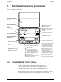
1.5 Front Panel Connections and Controls
Figure 1-1. ECA 450 Components
RS 232
POWER
OPT
T-STACK T-AIR
PRESSUREGAS
P REF
ECA 450
SET UP
CALIBRATE
MEMORY
FUEL
MENU
PRINT
POWER
I/O
RUN
SAVE
ENTER
V
ESC
PRESSURE
PRINT
– Prints contents of either the
Combustion Test or Pressure screen
on local printer.
SAVE – Saves to memory the contents
of the Combustion Test or Pressure
screen. Saved data can later be
recalled for viewing on the display, or
downloaded to a personal computer.
MENU
– Steps display from the
Combustion Test screen through the
Setup List, Calibrate, Fuel, Pressure,
and Memory menu screens.
Alternately, a particular menu screen
can be directly displayed by pressing
its associated shortcut key.
I/O
– Turns analyzer ON and OFF.
RUN – Starts and stops a combustion
efficiency test.
SET UP
– Displays Setup List
screen.
CALIBRATE
– Displays Calibrate
screen.
FUEL
– Displays Fuel screen.
PRESSURE – Displays Pressure
screen.
MEMORY – Displays Memory
screen.
ESC
– Displays previous menu or previously
viewed screen.
– Moves cursor left.
– Moves cursor up through screen, or
increments an alphanumerical value.
– Moves cursor down through screen, or
decrements an alphanumerical value.
– Moves cursor right.
ENTER – Chooses a menu item that has been
selected by the cursor's position.
VACUUM FLUORESCENT
DISPLAY PANEL
(4 Lines by 20 Characters)
PRINTER
BATTERY CHARGER/
AC ADAPTER CONNECTOR
RS 232 CONNECTOR
P REF
– Differential pressure
reference hose connector
GAS – Probe's stack hose connector
PRESSURE – Probe's draft hose
connector
T-STACK – Probe's Flue-gas
thermocouple connector
T-AIR
– Primary air thermocouple
connector
OPT
– Option connector
STORAGE COMPARTMENT
6" x 18" x 3"
SENSOR COMPARTMENT
SHORTCUT MENU KEYS:
P / P
1.5.1 GAS, PRESSURE, T-STACK (Probe)
Attach the supplied probe to the analyzer by connecting its . . .
• flue-gas thermocouple to the analyzer’s T-STACK connector,
• flue-gas hose (yellow band) to the analyzer’s GAS connector,
• draft hose (blue band) to the analyzer’s PRESSURE connector.
Observe that the probe’s connectors are of different sizes and shapes, which
prevent misconnection to their associated connectors on the analyzer.

ECA 450 Introduction
Instruction 0024-9400
7
1.5.2 T-AIR (Primary Air Thermocouple)
If thermocouple 0104-1797 (10 feet long) or Utility Wand 0104-1799 (12 inch
ridged probe with handle and 5 foot coiled cable) is to be used to measure the
burner’s primary air temperature, then connect either thermocouple to the
analyzer’s T-AIR connector.
Refer to Section 2.14 Primary Air Temperature Measurement for alternate
methods of measuring the burner’s primary air temperature.
1.5.3 POWER (AC Adapter)
The analyzer’s internal battery pack is charged by connecting the supplied
AC adapter to any convenient source of 100–240 VAC, 50/60 Hz power, and
then connecting the charger’s output plug to the analyzer’s POWER
connector. Refer to Section 4.1 Battery Charging.
The AC adapter can also be used as an external power supply to simulta-
neously charge and run the analyzer if its battery pack should become
depleted during use.
1.5.4 ∆P REF (Differential Pressure)
The Differential pressure between two areas can be measured by first
connecting pressure hose P/N 0024-1103 to the analyzer’s ∆P REF connector,
and inserting the open end of this hose into the area being used as the
reference pressure. The analyzer’s probe is then inserted into the area who’s
differential pressure is to be measured. Refer to Section 2.15 Differential
Pressure Measurement.
1.5.5 RS232 (Computer Interface)
Data that has been stored in analyzer’s memory can be sent to a personal
computer by connecting serial data cable P/N 0104-4027 (straight through,
6 foot, DB9 male to DB9 female) between the computer’s COM port and the
analyzer’s RS232 connector. Refer to Section 2.11 Downloading Data to a
Personal Computer.
1.5.6 OPT (Option)
Connector for future optional equipment.

Introduction ECA 450
8 Instruction 0024-9400
1.6 Front Panel Keypad Controls
Descriptions of the front panel keypad controls are given below. Note that a
control may perform multiple functions as determined by what screen is
being displayed at the time.
I/O
Turns the analyzer ON and OFF. Note that when the analyzer
is turned OFF, there is a 5 second off-delay period that allows
an operator to turn the analyzer back ON by pressing the RUN
key. Also note that if there are unsafe levels of gas present
inside the analyzer when it is turned OFF, the analyzer’s pump
is automatically started and purges the sensor compartment
with fresh air. The analyzer will turn OFF only after the gas
levels have been reduced. If desired, the purging process can be
aborted by again pressing the I/O key.
RUN
Starts and stops a combustion efficiency test when the Com-
bustion Test RUN/HOLD screen is displayed. Pressing this key
from any of the menu screens returns the analyzer to the
Combustion Test HOLD screen. Pressing this key during the
5 second turn-off-delay period, or from the warm-up screen
whenever sensor errors are being displayed, will also cause the
Combustion Test HOLD screen to be displayed.
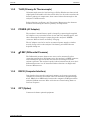
PRINT
Prints the contents of either the Combustion Test or Pressure
screen on the local printer. This key is inactive in all other
screens.
SAVE
Saves the contents of the Combustion Test or Pressure screen
to memory. The saved data can then later be recalled for
viewing on the display and printed or downloaded to a personal
computer.
MENU
Cycles the display from the Combustion Test screen though the
following menu screens: Fuel, Pressure, Memory, Setup List,
and Calibration List. These menu screens can also be directly
accessed by pressing their associated shortcut key.
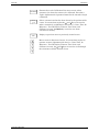
FUEL
Shortcut key to the Fuel menu screen, where operators can
choose which fuel is being burned.
PRESSURE
P / P
Shortcut key to the Pressure menu screen, where operators can
view the pressure being sampled by the probe. Pressing this
key a second time allows an operator to zero the pressure
sensor.
MEMORY
Shortcut key to the Memory menu screen, where operators can
choose to either view the Memory Directory screen, transmit
saved data out the analyzer’s RS232 port, or clear memory.
SETUP
Shortcut key to the Setup List menu screen, where operators
can choose to change various operating parameters of the
analyzer.

ECA 450 Introduction
Instruction 0024-9400
9
CALIBRATE
Shortcut key to the Calibration List menu screen, where
operators can choose the sensor to be calibrated. Note that a
4-place alphanumerical password must first be entered to begin
calibration.
ENTER
Selects a menu item that has been chosen by the position of the
cursor. In screens that require the
∧
and
∨
keys to be used to
make a numerical or alphabetical selection (i.e., Date, Time, O
2
Reference., Test ID, Display Timeout, User Name, and
Calibrate screens), the
ENTER key is used to save those
selections to memory.
ESC
Displays a previous menu or previously viewed screen.
Moves cursor in direction of arrow. In screens that require an
operator to enter alphanumerical data (i.e., Date, Time, O
2
Reference., Test ID, Display Timeout, User Name, and
Calibrate screens), the
∧
and
∨
keys are used to scroll through
the selections available for that screen.

Introduction ECA 450
10 Instruction 0024-9400
Notes:

ECA 450 Operation
Instruction 0024-9400
11
2 Operation
2.1 Turning On the Analyzer
Important! Prior to initially operating the analyzer, be sure to first charge the
battery per Section 4.1.
Before turning on the analyzer, connect the probe’s gas hose, pressure hose,
and thermocouple to the analyzer’s GAS, PRESSURE, and T-STACK
connectors, respectively (refer to Section 1.5.1).
Turn on the analyzer by pressing the I/O key. Observe that all display
segments are briefly turned on to verify their operation. The display then
shows the following information as the analyzer performs its 60 second
warm-up sequence:
BACHARACH, INC
ECA 450
WARM-UP xx
Where: xx = warm-up time, counting down from 60 seconds
Note: The software’s version number is briefly displayed at the bottom of the
screen prior to the start of the warm-up sequence.
At the end of a normal warm-up sequence, the message “No Problems
Detected” is briefly displayed followed by the display of the Combustion Test
HOLD screen. If, however, a problem was detected during warm-up, the
analyzer will display the message “Problem(s) Detected” and sequentially
display a list of those problems at the bottom of the screen, and then wait for
operator intervention. Refer to Section 5.2 Troubleshooting Guide for a list of
possible error messages and the recommended corrective action.
2.2 Turning Off the Analyzer
The analyzer is turned off by again pressing the I/O key. If there is any
residual gas inside the sensor chamber, the message “Purging Sensors” is
displayed while the analyzer purges itself with fresh air. The purging process
continues until all gas concentrations inside the analyzer have reached safe
levels.
Once the sensor chamber has been purged, the analyzer enters its normal 5-
second-delay period; after which the analyzer turns off.
Important! The probe must be removed from the stack during the purging
process to allow fresh air to be drawn through the sensor chamber.
Tips: Pressing the I/O key will abort the purging process. During the off-delay
period, the analyzer can be turned back on by pressing the RUN key.

Operation ECA 450
12 Instruction 0024-9400
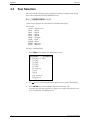
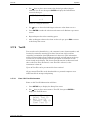
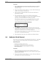
2.3 Fuel Selection
The fuel currently being used for combustion analysis is displayed in the top
line of the Combustion Test RUN/HOLD screen.
«HOLD««««««««««NGAS«
In the above example, the current fuel is NGAS (natural gas).
Fuel Codes:
NGAS = Natural Gas
OIL2 = Oil #2
OIL4 = Oil #4
OIL5 = Oil #5
OIL6 = Oil #6
PROP = Propane
COAL = Coal
WOOD = Wood
KERO = Kerosene
BGAS = Bagasse
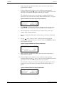
To select a different fuel:
1. Press FUEL key to display the Fuel menu screen.
«««««««FUEL«««««««
ª Natural Gas
Oil#2
Oil#4
Oil#5
Oil#6
Propane
Coal
Wood
Kerosene
Bagasse
2. Use ∧∨ keys to scroll through fuel list until cursor is next to desired fuel.
3. Press ENTER key to store the fuel selection in memory. The
corresponding fuel code should now appear in the upper-right hand corner
of the Combustion Test HOLD screen.

ECA 450 Operation
Instruction 0024-9400
13
2.4 Performing a Combustion Test
Important! When measuring nitrogen dioxide (NO
2
) and sulfur dioxide (SO
2
),
it is recommended that a Sampler Conditioner (Bacharach P/N 0024-7224) be
used to assure accurate readings.
1. If not already done, turn on analyzer (Section 2.1) and select a fuel
(Section 2.3).
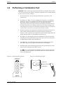
2. See Figure 2-1. Make a ½-inch sampling hole in stack to accommodate
probe stop. Locate this sampling hole before any draft diverter/hood or
barometric damper so that flue gasses are not diluted and stack
temperature has not been decreased by surrounding air used to balance
the draft. Note that as the distance between the last heat exchanger and
sampling point increases, the calculated combustion efficiency will falsely
increase due to heat loss by convection from the flue or stack.
3. If burner’s primary-air temperature is different from that of room air, be
sure to either immerse primary-air thermocouple into primary-air
stream, or take a primary-air temperature measurement using either the
probe’s thermocouple or a thermometer (Section 2.14).
4. See Figure 2-2. Screw probe stop into sampling hole. Next, insert probe
through probe stop, positioning its tip near center of stack. Secure probe
by tightening the probe stop’s thumbscrew.
5. Press RUN key. You should hear the pump start running and see the
word RUN appear in the upper-left hand corner of the display.
6. The ECA 450 is now continuously measuring and calculating the values
shown in the Combustion Test RUN screen.
Use
∧∨ keys to scroll through the following typical set of data (note that
depending on which sensors are installed, some of the data listed below
may not be displayed).
Figure 2-1. Sampling Hole Location Figure 2-2. Installing the Probe
FLUE GAS FLOW
(Downstream)
DRAFT
DIVERTER/
REGULATOR
SAMPLE
HOLE
(Upstream)
FURNACE
BREECHING
PROBE STOP
THUMBSCREW

Operation ECA 450
14 Instruction 0024-9400
7. Tip: Use < > keys to quickly advance to the top and bottom of screen.
Also note that if “– – – –”, “x x x x”, or “* * * *” appear in a data field,
then data cannot be displayed for that measurement. Refer to Section 5.3
Error Symbols for an explanation of these symbols and why data is not
being displayed.
O2 = % Oxygen
CO = Carbon Monoxide
(1)
EFF = % Combustion Efficiency
CO2 = % Carbon Dioxide
T-STACK = Stack Temperature
T-AIR = Room/Primary-Air Temperature
EA = % Excess Air
NO = Nitric Oxide
(1)
NO2 = Nitrogen Dioxide
(1)
NOX = Oxides of Nitrogen (combination of NO and NO
2
)
(1)
SO2 = Sulfur Dioxide
(1,3)
HC = % Combustibles (Methane based)
CO(n) = Carbon Monoxide content referenced to a percentage of
Oxygen
(2)
NO(n) = Nitric Oxide referenced to a percentage of Oxygen
(2)
NO2(n) = Nitrogen Dioxide referenced to a percentage of Oxygen
(2)
NOX(n) = Oxides of Nitrogen (combination of NO and NO
2
)
referenced to a percentage of Oxygen
(2)
SO2(n) = Sulfur Dioxide referenced to a percentage of Oxygen
(2)
(1)
Unit of measure is determined by the selected Pollution Units. Refer to
Section 2.17.3.
(2)
The letter “n” represents the operator’s selected Oxygen reference level
of between 0 and 15%. Refer to Section 2.17.7.
(3)
The SO
2
sensor cannot be installed without the NO
2
sensor also being
installed.
8. Use ∧∨ keys to scroll to the T-STACK reading. Loosen thumbscrew on
probe stop and move probe in and out of the stack until stack’s core
temperature (hot spot) is located; then tighten thumbscrew to prevent
further movement of probe. Locating the highest stack temperature is very
important in obtaining accurate efficiency calculation results.
9. Burner-service procedures can now begin. The readings on the analyzer
will quickly change to show changes in burner performance.
10. If desired, combustion test readings can be saved. Refer to Section 2.7
Saving Test Data.
CAUTION: The sensors could become damaged if water enters the
analyzer. Drain the water condensate in the Water-Trap / Filter Assembly
as necessary during a combustion test as described in Step 10.
11. During an efficiency test, periodically check water level inside the probe’s
Water-Trap / Filter Assembly. With this assembly stood up on its Outlet
End, do not let water condensate build up beyond tip of riser tube. Drain
water condensate after every combustion test. For additional information
on this subject, refer to Section 4.2 Water-Trap / Filter Assembly.

ECA 450 Operation
Instruction 0024-9400
15
2.5 Ending a Combustion Test
1. After performing a combustion test per Section 2.4, press RUN key to end
the test. You should hear the pump stop running.
WARNING: Burn hazard! Take all necessary precautions when handling a
hot probe and probe stop.
CAUTION: Allow a hot probe and probe stop to cool before storing them
inside the analyzer’s carrying case.
2. Loosen thumbscrew on probe stop; then remove probe and probe stop
from stack.
Note: If data was saved during the combustion test, the analyzer can be
safely turned off without loosing the saved data, which can be reviewed at
a later time as described in Section “2.9 Recalling Test Data Stored in
Memory.”
3. Turn off analyzer per Section 2.2 Turning Off the Analyzer.
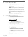
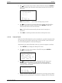
2.6 Performing a Draft Measurement
1. If not already done, turn on analyzer and place probe inside stack as
previously described (Sections 2.1 and 2.4).
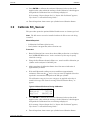
2. Press PRESSURE key to display the Pressure screen.
««««««PRESSURE««««««
n.nn xxxx
Where: n.nn = current pressure reading
xxxx = pressure units (refer to Section 2.17.2)
3. If desired, pressure sensor can be zeroed at this time as described below.
To skip the zeroing procedure, proceed to Step 4.
a) With Pressure screen displayed, again press PRESSURE key to
display the Pressure Zero screen.
Pressure Zero
Disconnect Hose
Then Press ENTER
b) Disconnect probe’s pressure hose from analyzer’s PRESSURE
connector.
c) Press ENTER to zero pressure sensor to atmospheric pressure; after
which, reconnect probe hose that was removed in Step 3b.
Reconnect Hose
4. The Pressure screen is now displaying the stack’s draft value as a
negative pressure.

Operation ECA 450
16 Instruction 0024-9400
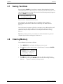
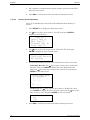
2.7 Saving Test Data
By pressing the SAVE key, data that is currently being displayed in either
the Combustion Test or Pressure screen is stored in one of the analyzer’s over
1000 internal memory locations. Observe that the following message appears
when the SAVE key is pressed.
Saving Memory
Location nnnn
Where: nnnn = memory location number
At a later time, the stored data can be recalled for either viewing or
downloading as described in Section 2.9 Recalling Test Data Stored in
Memory.
Once all memory locations are filled, an attempt to save additional data will
cause the message “Memory Full” to be momentarily displayed. To save
additional data, memory must first be cleared per Section 2.8 Clearing
Memory.
Tip: Before clearing memory, its contents can be downloaded to a personal
computer for permanent storage per Section 2..11.
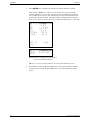
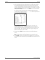
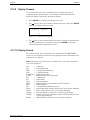
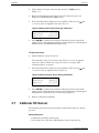
2.8 Clearing Memory
Clear all memory locations as follows:
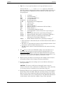
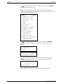
1. Press MEMORY key to display the Memory menu screen.
2. Use ∧∨ keys to place cursor next to “Clear Memory”; then press ENTER.
«««««««MEMORY«««««««
Memory Directory
Transmit Memory
ª Clear Memory
3. Use ∧∨ keys to place cursor next to “Yes” (or “No” if you decide not to
clear memory); then press ENTER. Observe that the message “Clearing
Memory . . .” appears as memory is being cleared.
Page is loading ...
Page is loading ...
Page is loading ...
Page is loading ...
Page is loading ...
Page is loading ...
Page is loading ...
Page is loading ...
Page is loading ...
Page is loading ...
Page is loading ...
Page is loading ...
Page is loading ...
Page is loading ...
Page is loading ...
Page is loading ...
Page is loading ...
Page is loading ...
Page is loading ...
Page is loading ...
Page is loading ...
Page is loading ...
Page is loading ...
Page is loading ...
Page is loading ...
Page is loading ...
Page is loading ...
Page is loading ...
Page is loading ...
Page is loading ...
Page is loading ...
Page is loading ...
Page is loading ...
Page is loading ...
Page is loading ...
Page is loading ...
Page is loading ...
Page is loading ...
Page is loading ...
Page is loading ...
Page is loading ...
Page is loading ...
Page is loading ...
Page is loading ...
Page is loading ...
Page is loading ...
Page is loading ...
Page is loading ...
Page is loading ...
Page is loading ...
Page is loading ...
Page is loading ...
Page is loading ...
Page is loading ...
Page is loading ...
Page is loading ...
Page is loading ...
Page is loading ...
Page is loading ...
Page is loading ...
Page is loading ...
Page is loading ...
Page is loading ...
Page is loading ...
Page is loading ...
Page is loading ...
-
 1
1
-
 2
2
-
 3
3
-
 4
4
-
 5
5
-
 6
6
-
 7
7
-
 8
8
-
 9
9
-
 10
10
-
 11
11
-
 12
12
-
 13
13
-
 14
14
-
 15
15
-
 16
16
-
 17
17
-
 18
18
-
 19
19
-
 20
20
-
 21
21
-
 22
22
-
 23
23
-
 24
24
-
 25
25
-
 26
26
-
 27
27
-
 28
28
-
 29
29
-
 30
30
-
 31
31
-
 32
32
-
 33
33
-
 34
34
-
 35
35
-
 36
36
-
 37
37
-
 38
38
-
 39
39
-
 40
40
-
 41
41
-
 42
42
-
 43
43
-
 44
44
-
 45
45
-
 46
46
-
 47
47
-
 48
48
-
 49
49
-
 50
50
-
 51
51
-
 52
52
-
 53
53
-
 54
54
-
 55
55
-
 56
56
-
 57
57
-
 58
58
-
 59
59
-
 60
60
-
 61
61
-
 62
62
-
 63
63
-
 64
64
-
 65
65
-
 66
66
-
 67
67
-
 68
68
-
 69
69
-
 70
70
-
 71
71
-
 72
72
-
 73
73
-
 74
74
-
 75
75
-
 76
76
-
 77
77
-
 78
78
-
 79
79
-
 80
80
-
 81
81
-
 82
82
-
 83
83
-
 84
84
-
 85
85
-
 86
86


Bacharach ECA 450 User manual
- Category
- Measuring, testing & control
- Type
- User manual
- This manual is also suitable for
Ask a question and I''ll find the answer in the document
Finding information in a document is now easier with AI
Related papers
-
Bacharach PCA® 400 User manual
-
-
Bacharach 24-9448 User manual
-
-
-
-
-
-
-
Other documents
-
 Lascar Electronics EasyLog EL-EnviroPad-TC Quick start guide
-
 AND AX-MX-43 User manual
-
Hach HQ14d User manual
-
 Teledyne Max-5 User manual
-
 UEi Smart Bell PLUS User manual
-
 UEi Smart Bell PLUS User manual
-
 UEi Eagle Owner's manual
-
 MRU Instruments OPTIMA 7 Biogas Operating instructions
-
 UEi Eagle Owner's manual
-
UEi Test Instruments C155 User manual


