INSTALLATION INSTRUCTIONS:
1.
Before installing, disconnect power by turning off circuit breaker
or removing fuse from fuse box .
2.
IMPORTANT: Determine ground side of track (has indented groove on face
and two internal copper bars) and the connector (side of connector with two metal tabs). Can only be assembled
if the grounds are aligned. 3. Loosen set screw on dead end cap at appropriate track end and remove. Loosen
set screw on connector. 4. Aligning the ground sides of the track and connector, push connector into open end of
track. Tighten set screws. 5. Remove steel box cover. Remove 7/8” knokcout and attach appropriate conduit
connector. 6. Place track/connector assembly against ceiling and proceed with installation as described in track
instructions. 7. Attach appropriate conduit with supply wires to conduit connector. 8. Remove connector cover
and feed supply wires through hole on connector. 9. Attach the white (-) wire to silver screw on connector; attach
black (+) wire to brass screw; attach green (ground) wire to green screw on connector. Replace connector cover
and steel box cover.
CONDUIT CONNECTOR
CONECTOR AL CONDUCTO ELÉCTRICO
Connects a track section to flex or hard pipe conduit at track end.
For use with Hampton Bay series track system. 60Hz 120V
INSTRUCCIONES DE INSTALACI
Ó
N Y OPERACI
ÓN:
1.
Antes de comenzar la instalaci
ó
n,
desconecte la electricidad desactivando el disyuntor o quitando el fusible de la caja de fusibles.
2.
IMPORTANTE:Determine cu
a
l es el lado a tierra del rie
l (tiene una ranura en el lado anterior y dos barras
interiores de cobre) y del conector (el lado con dos leng
u
etas de metal). A pesar de no ser un accesorio con
conexi
o
n a tierra,el mismo podr
a
ensamblarse
u
nicamente si los lados a tierra est
a
n alineados.
Quite la cubierta
protecora.
3.
Coloque la cubierta protectora sobre la caja de conexiones del techo.Escoja el lado de las ranuras
que pueda alinearse a la caja de conexiones con los tornillos y marque la cubierta protectora donde van los
mismos.Abra un agu
jero en las marcas.Inserte los cables de suministro de energ
i
a a trav
e
s de la cubierta y
affiance
la misma con los tornillos incluidos en la caja.
4.
Afloje el tornillo sujetador en la cubierta de extremo y
qu
i
telo.Afloje los tornillos.
5.
Quite la tapa de la metal del conector. Quite la parte punchout circular del conector
y coloque el conector apropiado para el conduit. 6. Conloque el ensamblaje de riel y conector contra el techo y
proceda a la instalación tal como está descritaen las instrucciones del riel. 7. Conecte el conduit apropiado con
cables de alimentación al conector del conduit. 8. Quite la cubierta del conector y coloque los cables de
alimentación a través del orificio del conector. 9. Conecte el cable (-) blanco al tornillo plateado del conector,
conecte el cable (+) negro al tornillo de bronce, conecte el cable verde (tierra) al tornillo verde del conector.
Vuelva a colocar las tapas del conector y de la caja de acero.
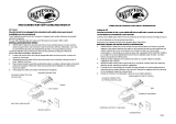
TRACK
CONNECTOR
BLACK WIRE
GROUND WIRE (BARE OR GREEN)
SILVER SCREW
BRASS PLATED SCREW
WHITE WIRE
GROUND SCREW
FLAT HD. SCREW (SMALL)
FLAT HD. SCREW (LARGE)
METAL COVER
CONNECTOR COVER
CONDUIT CONNECTION
RIEL
CONECTOR
CABLE NEGRO
CABLE PARA CONEXI A TIERRA
(PELADO O COLOR VERDE)
TORNILLO PLATEADO
TORNILLO PARA TIERRA
CABLE BLANCO
TORNILLO PARA TIERRA
TORNILLO SUJETADOR (PEQU NO)
TORNILLO SUJETADOR (GRANDE)
CUBIERTA METLICA
CUBIERTA DEL CONECTOR
CONEXIN AL CONDUCTO EL CTRICO
/


