
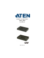
HDBaseT 2.0 KVM Extender
CE820 / CE920
User Manual
www.aten.com

CE820 / CE920 User Manual
ii
Preface
EMC Information
FEDERAL COMMUNICATIONS COMMISSION INTERFERENCE
STATEMENT: This equipment has been tested and found to comply with the
limits for a Class A digital device, pursuant to Part 15 of the FCC Rules. These
limits are designed to provide reasonable protection against harmful
interference when the equipment is operated in a commercial environment.
This equipment generates, uses, and can radiate radio frequency energy and, if
not installed and used in accordance with the instruction manual, may cause
harmful interference to radio communications. Operation of this equipment in
a residential area is likely to cause harmful interference in which case the user
will be required to correct the interference at his own expense.
The device complies with Part 15 of the FCC Rules. Operation is subject to the
following two conditions: (1) this device may not cause harmful interference,
and (2) this device must accept any interference received, including
interference that may cause undesired operation.
FCC Caution: Any changes or modifications not expressly approved by the
party responsible for compliance could void the user's authority to operate this
equipment.
Warning: Operation of this equipment in a residential environment could
cause radio interference.
Suggestion: Shielded twisted pair (STP) cables must be used with the unit to
ensure compliance with FCC & CE standards.
KCC Statement

CE820 / CE920 User Manual
iii
RoHS
This product is RoHS compliant.
User Information
Online Registration
Be sure to register your product at our online support center:
Telephone Support
For telephone support, call this number:
User Notice
All information, documentation, and specifications contained in this manual
are subject to change without prior notification by the manufacturer. The
manufacturer makes no representations or warranties, either expressed or
implied, with respect to the contents hereof and specifically disclaims any
warranties as to merchantability or fitness for any particular purpose. Any of
the manufacturer's software described in this manual is sold or licensed as is.
Should the programs prove defective following their purchase, the buyer (and
not the manufacturer, its distributor, or its dealer), assumes the entire cost of all
necessary servicing, repair and any incidental or consequential damages
resulting from any defect in the software.
The manufacturer of this system is not responsible for any radio and/or TV
interference caused by unauthorized modifications to this device. It is the
responsibility of the user to correct such interference.
The manufacturer is not responsible for any damage incurred in the operation
of this system if the correct operational voltage setting was not selected prior
to operation. PLEASE VERIFY THAT THE VOLTAGE SETTING IS
CORRECT BEFORE USE.
International http://eservice.aten.com
International 886-2-8692-6959
China 86-400-810-0-810
Japan 81-3-5615-5811
Korea 82-2-467-6789
North America 1-888-999-ATEN ext 4988
1-949-428-1111

CE820 / CE920 User Manual
iv
Package Contents
CE820 USB HDMI HDBaseT 2.0 KVM Extender
CE820 Package Contents
1 CE820L USB HDMI HDBaseT 2.0 KVM Extender (Local Unit)
1 CE820R USB HDMI HDBaseT 2.0 KVM Extender (Remote Unit)
1 HDMI KVM Cable Set
2 Power Adapters
2 Mounting Kits
8 Foot Pads
1 User Instructions
CE820L Package Contents
1 CE820L USB HDMI HDBaseT 2.0 KVM Extender (Local Unit)
1 HDMI KVM Cable Set
1 Power Adapter
1 Mounting Kit
4 Foot Pads
1 User Instructions
CE820R Package Contents
1 CE820R USB HDMI HDBaseT 2.0 KVM Extender (Remote Unit)
1 Power Adapter
1 Mounting Kit
4 Foot Pads
1 User Instructions

CE820 / CE920 User Manual
v
CE920 USB DisplayPort HDBaseT 2.0 KVM Extender
CE920 Package Contents
1 CE920L USB DisplayPort HDBaseT 2.0 KVM Extender (Local Unit)
1 CE920R USB DisplayPort HDBaseT 2.0 KVM Extender (Remote
Unit)
1 Microphone Cable
1 Speaker Cable
1 USB Type-A to Type-B Cable
1 DisplayPort Cable
2 Mounting Kits
2 Power Adapters
1 User Instructions
CE920L Package Contents
1 CE920L USB DisplayPort HDBaseT 2.0 KVM Extender (Local Unit)
1 Microphone Cable
1 Speaker Cable
1 USB Type-A to Type-B Cable
1 DisplayPort Cable
1 Mounting Kit
1 Power Adapter
1 User Instructions
CE920R Package Contents
1 CE920R USB DisplayPort HDBaseT 2.0 KVM Extender (Remote
Unit)
1 Mounting Kit
1 Power Adapter
1 User Instructions
Check to make sure that all the components are present and that nothing got
damaged in shipping. If you encounter a problem, contact your dealer.
Read this manual thoroughly and follow the installation and operation
procedures carefully to prevent any damage to the unit, and/or any of the
devices connected to it.

CE820 / CE920 User Manual
vi
* Features may have been added to the HDBaseT 2.0 KVM Extender since this
manual was published. Please visit our website to download the most up-to-
date version of the manual.

CE820 / CE920 User Manual
vii
Contents
Preface
EMC Information . . . . . . . . . . . . . . . . . . . . . . . . . . . . . . . . . . . . . . . . . . . . . ii
RoHS. . . . . . . . . . . . . . . . . . . . . . . . . . . . . . . . . . . . . . . . . . . . . . . . . . . . . .iii
User Information . . . . . . . . . . . . . . . . . . . . . . . . . . . . . . . . . . . . . . . . . . . . .iii
Online Registration . . . . . . . . . . . . . . . . . . . . . . . . . . . . . . . . . . . . . . . .iii
Telephone Support . . . . . . . . . . . . . . . . . . . . . . . . . . . . . . . . . . . . . . . .iii
User Notice . . . . . . . . . . . . . . . . . . . . . . . . . . . . . . . . . . . . . . . . . . . . . .iii
Package Contents . . . . . . . . . . . . . . . . . . . . . . . . . . . . . . . . . . . . . . . . . . iv
CE820 USB HDMI HDBaseT 2.0 KVM Extender . . . . . . . . . . . . . . . . iv
CE820 Package Contents . . . . . . . . . . . . . . . . . . . . . . . . . . . . . . iv
CE820L Package Contents . . . . . . . . . . . . . . . . . . . . . . . . . . . . . . iv
CE820R Package Contents. . . . . . . . . . . . . . . . . . . . . . . . . . . . . . iv
CE920 USB DisplayPort HDBaseT 2.0 KVM Extender . . . . . . . . . . . . v
CE920 Package Contents . . . . . . . . . . . . . . . . . . . . . . . . . . . . . . . v
CE920L Package Contents . . . . . . . . . . . . . . . . . . . . . . . . . . . . . . . v
CE920R Package Contents. . . . . . . . . . . . . . . . . . . . . . . . . . . . . . . v
About this Manual . . . . . . . . . . . . . . . . . . . . . . . . . . . . . . . . . . . . . . . . . . ix
Conventions . . . . . . . . . . . . . . . . . . . . . . . . . . . . . . . . . . . . . . . . . . . . . . . . x
Product Information. . . . . . . . . . . . . . . . . . . . . . . . . . . . . . . . . . . . . . . . . . . x
1. Introduction
Overview . . . . . . . . . . . . . . . . . . . . . . . . . . . . . . . . . . . . . . . . . . . . . . . . . . . 1
Features . . . . . . . . . . . . . . . . . . . . . . . . . . . . . . . . . . . . . . . . . . . . . . . . . . . 2
Requirements . . . . . . . . . . . . . . . . . . . . . . . . . . . . . . . . . . . . . . . . . . . . . . . 3
Consoles . . . . . . . . . . . . . . . . . . . . . . . . . . . . . . . . . . . . . . . . . . . . . . . 3
Computers. . . . . . . . . . . . . . . . . . . . . . . . . . . . . . . . . . . . . . . . . . . . . . . 3
Cables . . . . . . . . . . . . . . . . . . . . . . . . . . . . . . . . . . . . . . . . . . . . . . . . . . 3
Components . . . . . . . . . . . . . . . . . . . . . . . . . . . . . . . . . . . . . . . . . . . . . . . . 5
CE820L Front and Rear View . . . . . . . . . . . . . . . . . . . . . . . . . . . . . . . 5
CE820R Front and Rear View . . . . . . . . . . . . . . . . . . . . . . . . . . . . . . . 6
CE920L Front and Rear View . . . . . . . . . . . . . . . . . . . . . . . . . . . . . . . 7
CE920R Front and Rear View . . . . . . . . . . . . . . . . . . . . . . . . . . . . . . . 8
2. Hardware Setup
Stacking and Rack Mounting . . . . . . . . . . . . . . . . . . . . . . . . . . . . . . . . . . . 9
Stacking. . . . . . . . . . . . . . . . . . . . . . . . . . . . . . . . . . . . . . . . . . . . . . . . . 9
Rack Mounting . . . . . . . . . . . . . . . . . . . . . . . . . . . . . . . . . . . . . . . . . . . 9
Installation . . . . . . . . . . . . . . . . . . . . . . . . . . . . . . . . . . . . . . . . . . . . . . . . 10
Grounding . . . . . . . . . . . . . . . . . . . . . . . . . . . . . . . . . . . . . . . . . . . . . . 10
Setting Up . . . . . . . . . . . . . . . . . . . . . . . . . . . . . . . . . . . . . . . . . . . . . .11
CE820 . . . . . . . . . . . . . . . . . . . . . . . . . . . . . . . . . . . . . . . . . . . . . . 11
CE920 . . . . . . . . . . . . . . . . . . . . . . . . . . . . . . . . . . . . . . . . . . . . . . 13

CE820 / CE920 User Manual
viii
3. Operation
Overview. . . . . . . . . . . . . . . . . . . . . . . . . . . . . . . . . . . . . . . . . . . . . . . . . . 15
LED Display . . . . . . . . . . . . . . . . . . . . . . . . . . . . . . . . . . . . . . . . . . . . 15
Long Reach Mode. . . . . . . . . . . . . . . . . . . . . . . . . . . . . . . . . . . . . . . . 15
Appendix
Safety Instructions . . . . . . . . . . . . . . . . . . . . . . . . . . . . . . . . . . . . . . . . . . 17
General . . . . . . . . . . . . . . . . . . . . . . . . . . . . . . . . . . . . . . . . . . . . . . . 17
Mounting . . . . . . . . . . . . . . . . . . . . . . . . . . . . . . . . . . . . . . . . . . . . . . 19
Technical Support . . . . . . . . . . . . . . . . . . . . . . . . . . . . . . . . . . . . . . . . . . 20
International . . . . . . . . . . . . . . . . . . . . . . . . . . . . . . . . . . . . . . . . . . . . 20
North America . . . . . . . . . . . . . . . . . . . . . . . . . . . . . . . . . . . . . . . . . . 20
Specifications . . . . . . . . . . . . . . . . . . . . . . . . . . . . . . . . . . . . . . . . . . . . . . 21
Limited Warranty. . . . . . . . . . . . . . . . . . . . . . . . . . . . . . . . . . . . . . . . . . . . 23

CE820 / CE920 User Manual
ix
About this Manual
This User Manual is provided to help you get the most from your CE820/
CE920 HDBaseT 2.0 KVM Extender. It covers all aspects of installation,
configuration, and operation. An overview of the information found in the
manual is provided below.
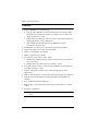
Chapter 1, Introduction, introduces you to the CE820/CE920 units. Their
purposes, features, and benefits are presented, and the functions of their panel
components are described.
Chapter 2, Hardware Setup, describes the steps that are necessary to
quickly and safely set up your CE820/CE920 units.
Chapter 3, Operation, explains the fundamental concepts involved in
operating the CE820/CE920 units.
An Appendix, provides specifications and other technical information
regarding the CE820/CE920 units.

CE820 / CE920 User Manual
x
Conventions
This manual uses the following conventions:
Product Information
For information about all ATEN products and how they can help you connect
without limits, visit ATEN on the Web or contact an ATEN Authorized
Reseller. Visit ATEN on the Web for a list of locations and telephone numbers:
Monospaced Indicates text that you should key in.
[ ] Indicates keys you should press. For example, [Enter] means to
press the Enter key. If keys need to be chorded, they appear
together in the same bracket with a plus sign between them:
[Ctrl+Alt].
1. Numbered lists represent procedures with sequential steps.
♦ Bullet lists provide information, but do not involve sequential steps.
→ Indicates selecting the option (on a menu or dialog box, for
example), that comes next. For example, Start
→
Run means to
open the Start menu, and then select Run.
Indicates critical information.
International http://www.aten.com

1
Chapter 1
Introduction
Overview
The CE820/CE920 HDBaseT 2.0 KVM Extender can extend HDMI (CE820
only), DisplayPort (CE920 only), serial, Ethernet, and USB 2.0 signals up to
100 meters using a single Cat 5e/6/6a or ATEN 2L-2910 cable and HDBaseT
technology. The HDBaseT 2.0 KVM Extender is equipped with USB
connectors which allow you to extend signal transmission of any USB device.
The USB functionality provides support for peripheral sharing, touch panel
control and file transfers. The CE820/CE920 ensures superior video quality
with 4096 x 2160 resolutions so that you get the most out of your HDMI /
DisplayPort-enabled displays.
The CE820/CE920 supports the HDBaseT™ 2.0 technology with which you
can extend the KVM installation up to 150 meters @ 1080p and preserve high-
quality video by enhancing bit error detection and correction to resist signal
interference.
The CE820/CE920 allows access to a computer system from a remote console
(USB keyboard, monitor, and mouse). It is perfect for use in any type of
installation where you need to place the console where it is conveniently
accessible, but you want the system equipment to reside in a safe location –
away from the dust and dirt of the factory floor, or the harsh environmental
influence of a construction site, for example. This allows users to deploy
system equipment over large distances.
The CE820/CE920 is useful for control and security purposes, where you can
have the system in a secure area with the console in the most convenient
location for user access. This is ideal for managing highly confidential data
systems.
The CE820/CE920 is ideal for transportation centers, medical facilities, and
shopping malls, industrial kiosks and for syncing files and folders between
computers. Setup is as easy as can be – simply connect the computer; run the
Cat 5e/6/6a or ATEN 2L-2910 cable up to 100 meters to the remote unit of the
CE820/CE920 and then plug the remote console into the remote unit of CE820/
CE920.

CE820 / CE920 User Manual
2
Features
Supports HDBaseT™ 2.0 technology
Extends video (HDMI for CE820 and DisplayPort for CE920), audio,
USB, RS-232, and Ethernet signals via a single Cat6 / 6a cable or an
ATEN 2L-2910 Cat 6 cable
Enhanced bit error detection and correction to resist signal interference
during high-quality video transmissions
Status detection and LED indication for HDBaseT™ signal
transmission on remote unit
EDID Buffer for smooth power-up and the highest quality display
HDMI: 3D, Deep Color, 1080P, 4K (for CE820)
HDCP 2.2 Compatible (for CE820)
HDCP Compatible (for CE920)
Long distance with superior video quality
HDBaseT™ Standard mode up to 4K @ 100 m (Cat 6/6a or ATEN 2L-
2910 Cat 6 cable)
HDBaseT™ Long-reach mode up to 1080P @ 150 m
Long Reach mode switch – switches between HDBaseT™ Standard and
Long Reach modes in a snap
Supports individual 2-channel stereo audio for high-quality audio
applications
USB 2.0 full speed ports – ensures fast transmission speeds for peripherals
Supports PC wakeup function via single pushbutton through RS-232
channel*
Easy Installation Rack Mounting Kit
Built-in 8KV / 15KV ESD protection (Contact voltage 8KV; Air voltage
15KV)
Firmware upgradeable
Note: * The computer has to support Wake Up Ring for this function to
work.

Chapter 1. Introduction
3
Requirements
Consoles
An HDMI monitor (CE820) or DisplayPort monitor (CE920) capable of
the highest resolution you will be using on any computer in the
installation.
A USB keyboard
A USB mouse
Computers
The following equipment must be installed on each computer that is to be
connected to the system:
An HDMI port (for CE820 only)
A DisplayPort port (for CE920 only)
A USB port for the keyboard/mouse
RS-232 serial port (optional)
Microphone and speaker ports (optional)
Cables
For optimal signal integrity, and reducing layout complexity, we strongly
recommend that you use the high quality custom cables provided in the
package.
For more information about suitable Cat 5e/6/6a or ATEN 2L-2910 cables
and setting up HDBaseT devices, refer to the ATEN HDBaseT Installation
Guide.
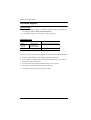
Maximum Cable Distances
CE820
Connection Distance
Computer to Local Unit (CE820L) 1.8 m
Local unit (CE820L) to remote unit (CE820R) 100 m*
Remote Unit (CE820R) to monitor 5 m

CE820 / CE920 User Manual
4
CE920
Note:
The maximum transmission distance using a Cat 5e/6/6a or ATEN
2L-2910 cable is 100m and 150m when Long Reach Mode is enabled
.
Connection Distance
Computer to Local Unit (CE920L) 1.8 m
Local unit (CE920L) to remote unit (CE920R) 100 m*
Remote Unit (CE920R) to monitor 1.8 m

Chapter 1. Introduction
5
Components
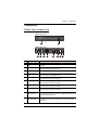
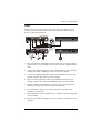
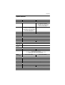
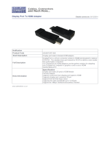
CE820L Front and Rear View
No. Component Description
1 RS-232 Serial
Port
Receives an RS-232 serial cable which connects to the local
computer.
2 LEDs Indicate the Link and Power status of the CE820L. For more
details, see LED Display, page 15.
3 Power Jack Receives the supplied power adapter.
4 HDBaseT Out
Port
Receives a Cat 5e/6/6a cable or an ATEN 2L-2910 cable
which connects to the CE820R unit.
5 Ethernet Port Receives a Cat 5e/6/6a cable or an ATEN 2L-2910 cable
which connects to the local computer.
6 HDMI In Port Receives the HDMI connect from the supplied KVM Cable Set
which connects to the local computer.
7 USB Type-B Port Receives a USB connector from the supplied KVM Cable Set
which connects to the local computer.
8 Audio Ports Receive audio connectors from the supplied KVM Cable Set
which connects to the local computer.
9 Long Reach
Mode Switch
Put the switch to ON to enable the Long Reach Mode to
transmit HDMI signals up to 150m, at 1080p. For details, see
Long Reach Mode, page 15.
10 Firmware
Upgrade Switch
This function is reserved for ATEN Technical Support. If you
would like to do a firmware upgrade yourself, please contact
your dealer.
1
3
3 4 5 7
8
6
11
CE820L Front View
CE820L Rear View
9
10
2

CE820 / CE920 User Manual
6
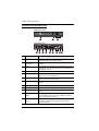
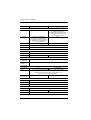
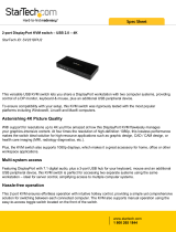
CE820R Front and Rear View
No. Component Description
1 RS-232 Serial Port Receives an RS-232 serial cable which connects to a
hardware/software serial control device.
2 Wake-up PC
Pushbutton
Press this button to remotely wake the computer on the
local side.
3 LEDs The CE820R has three LEDs on its back panel to indicate
its Video Out, Link, and Power status. For more details, see
LED Display, page 15.
4 Power Jack Receives the supplied power adapter.
5 HDBaseT In Port Receives a Cat 5e/6/6a cable or an ATEN 2L-2910 cable
which connects to the CE820L unit.
6 Ethernet Port Receives a Cat 5e/6/6a cable or an ATEN 2L-2910 cable
which connects to a network switch.
7 HDMI Out Port Receives an HDMI cable which connects to an HDMI
monitor.
8 Console Ports Receive the console keyboard and mouse.
9 USB Type-A Port Receives a USB 2.0 device.
10 Audio Ports Receive cables from the speaker (green) and microphone
(pink).
11 Long Reach Mode
Switch
Put the switch to ON to enable the Long Reach Mode to
transmit HDMI signals up to 150m, at 1080p. For details,
see Long Reach Mode, page 15.
12 Firmware Upgrade
Switch
This function is reserved for ATEN Technical Support. If you
would like to do a firmware upgrade yourself, please
contact your dealer.
21 3
12
10
11
4 5 6 7
CE820R Front View
CE820R Rear View
8
9

Chapter 1. Introduction
7
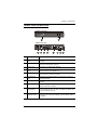
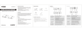
CE920L Front and Rear View
No. Component Description
1 RS-232 Serial
Port
Receives an RS-232 serial cable which connects to the local
computer.
2 LEDs Indicate the Link and Power status of the CE920L. For more
details, see LED Display, page 15.
3 Power Jack Receives the supplied power adapter.
4 HDBaseT Out
Port
Receives a Cat 5e/6/6a cable or an ATEN 2L-2910 cable
which connects to the CE920R unit.
5 Ethernet Port Receives a Cat 5e/6/6a cable or an ATEN 2L-2910 cable
which connects to the local computer.
6 DisplayPort In
Port
Receives the supplied DisplayPort cable which connects to
the local computer.
7 USB Type-B Port Receives the supplied USB Cable which connects to the local
computer.
8 Audio Ports Receive the supplied Microphone and Speaker Cables which
connect to the local computer.
9 Long Reach
Mode Switch
Put the switch to ON to enable the Long Reach Mode to
transmit HDMI signals up to 150m, at 1080p. For details, see
Long Reach Mode, page 15.
10 Firmware
Upgrade Switch
This function is reserved for ATEN Technical Support. If you
would like to do a firmware upgrade yourself, please contact
your dealer.
1
3 4 5 76
10
CE920L Front View
CE920L Rear View
2
8
9

CE820 / CE920 User Manual
8
CE920R Front and Rear View
No. Component Description
1 RS-232 Serial Port Receives an RS-232 serial cable which connects to a
hardware/software serial control device.
2 Wake-up PC
Pushbutton
Press this button to remotely wake the computer on the
local side.
3 LEDs The CE920R has three LEDs on its back panel to indicate
its Video Out, Link, and Power status. For more details, see
LED Display, page 15.
4 Power Jack Receives the supplied power adapter.
5 HDBaseT In Port Receives a Cat 5e/6/6a cable or an ATEN 2L-2910 cable
which connects to the CE920L unit.
6 Ethernet Port Receives a Cat 5e/6/6a cable or an ATEN 2L-2910 cable
which connects to a network switch.
7 DisplayPort Out
Port
Receives the supplied DisplayPort Cable which connects to
a monitor.
8 Console Ports Receive the console keyboard and mouse.
9 USB Type-A Port Receives a USB 2.0 device.
10 Audio Ports Receive cables from the speaker (green) and microphone
(pink).
11 Long Reach Mode
Switch
Put the switch to ON to enable the Long Reach Mode to
transmit HDMI signals up to 150m, at 1080p. For details,
see Long Reach Mode, page 15.
12 Firmware Upgrade
Switch
This function is reserved for ATEN Technical Support. If you
would like to do a firmware upgrade yourself, please
contact your dealer.
21
10
4 5 6 7
CE920R Front View
CE920R Rear View
3
8
9
1211

9
Chapter 2
Hardware Setup
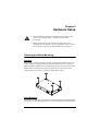
Stacking and Rack Mounting
Stacking
The CE820 / CE920 can be placed on any appropriate level surface that can
safely support its weight plus the weight of its attached cables. To place or
stack the CE820 / CE920, remove the backing material from the bottom of the
rubber feet that came with this package, and stick them onto the switch's
bottom panel at the corners, as shown in the diagram, below:
Rack Mounting
The CE820 / CE920 can be mounted on system racks using the supplied Rack
Mount Kit. For detailed setup instruction, see VE-RMK1U Installation Guide.
1. Important safety information regarding the placement of this
device is provided on page 17. Please review it before
proceeding.
2. Make sure that the power to all devices connected to the
installation are turned off. You must unplug the power cords of
any computers that have the Keyboard Power On function.

CE820 / CE920 User Manual
10
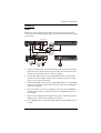
Installation
Grounding
To prevent damage to your installation it is important that all devices are
properly grounded.
1. Use a grounding wire to ground both units by connecting one end of the
wire to the grounding terminal, and the other end of the wire to a suitable
grounded object.
2. Make sure that the computer that connects to the Local Unit and the
monitor that connects to the Remote Unit are also grounded.
Cat 5e/6/6a cable
up to 100 m
Page is loading ...
Page is loading ...
Page is loading ...
Page is loading ...
Page is loading ...
Page is loading ...
Page is loading ...
Page is loading ...
Page is loading ...
Page is loading ...
Page is loading ...
Page is loading ...
Page is loading ...
-
 1
1
-
 2
2
-
 3
3
-
 4
4
-
 5
5
-
 6
6
-
 7
7
-
 8
8
-
 9
9
-
 10
10
-
 11
11
-
 12
12
-
 13
13
-
 14
14
-
 15
15
-
 16
16
-
 17
17
-
 18
18
-
 19
19
-
 20
20
-
 21
21
-
 22
22
-
 23
23
-
 24
24
-
 25
25
-
 26
26
-
 27
27
-
 28
28
-
 29
29
-
 30
30
-
 31
31
-
 32
32
-
 33
33


ATEN CE920 User manual
- Category
- Network extenders
- Type
- User manual
Ask a question and I''ll find the answer in the document
Finding information in a document is now easier with AI
Related papers

Other documents
-
Equip Mini DisplayPort - HDMI User manual
-
-
Kramer Electronics C-MDPMA/MDPMA-25 Datasheet
-
 Cables Direct HDHDPORT-005 Datasheet
-
Sunstech RP-R1100W Datasheet
-
ATEN Technology CE-300 User manual
-
iogear GVE440 Quick start guide
-
 StarTech.com SV231DPU2 Datasheet
-
 EiRA ER2661KVM HDMI KVM Point to Point Extender User manual
-
A-Neuvideo ANI-HDB70 User manual


