
MSC1512
v.1.1
MSC 12V/1,5A-24V/1A/M
PSU module for CCTV.
EN*
Edition: 4 from 30.11.2018
Supersedes the edition: 3 from 16.09.2013

www.pulsar.pl MSC1512
2
Features:
output voltage 12VDC/1,5A or 24VDC/1A
jumper selectable
supply voltage 16÷30VAC or 22÷42VDC
high efficiency: 90% max
LED indication
protections:
SCP short-circuit protection
OLP overload protection
surge protection
warranty – 5 year from the production date
CONTENTS:
1. Technical description.
1.1. General description
1.2. Block diagram
1.3 Description of components and connectors
1.4 Specifications
2. Installation.
2.1. Requirements
2.2. Installation procedure.
3. Operating status indication.
4. Operation and use.
4.1. Overload or short circuit
4.2. Maintenance
1. Technical description.
1.1. General description
The MSC1512 PSU module is intended for supplying devices that require voltage of 12V or 24V DC. The
module is designed as a supplying component in CCTV systems, KD access control, SSWiN alarm systems, etc. It
is intended to be wall-mounted or fixed inside a device (e.g. camera’s enclosure).
- The module delivers current of: 12V with current efficiency of 1,5A or 24V with current
efficiency of 1A.
When supplied with the maximum AC power, the module enables supplying 12V DC cameras for a
longer distance (approx. 2x) than in case of 13,8V DC supply (with the same cross-section and resistance
of the wires). The module does not hale galvanic insolation between input/output (AC-AUX). For correct operation
of the module, the appropriate input voltage and current efficiency of the power source shall be provided.
Voltage drop for typical wires used in CCTV systems (2x 0,5mm2/AWG20):
Load current
(P power of the device)
Voltage drop for the wire:
2 x 0,5mm2/100m (R= ~3Ω x2@100m)
DC, AC
0,5A (P=6W@12VDC)
3V
1A (P=12W@12VDC)
6V
1,5A (P=15W@12VDC)
9V
2A (P=21W@12VDC)
12V

www.pulsar.pl MSC1512
3
1.2. Block diagram (fig.1).
Fig.1. Block diagram of the PSU module.
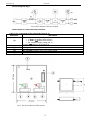
1.3 Description of components and connectors
Table 1. The components of the PSU module (see fig. 2).
Element no.
Description
[1]
J-Uout, pin- AUX output voltage adjustment
J-Uout = voltage AUX=12VDC*
J-Uout = voltage AUX=24VDC*
* - see: module’s supply voltage (tab. 3)
Caption: jumper on, jumper off
[2]
F1 fuse in the module’s power circuit
[3]
AUX, green LED: DC power indication
[4]
DC power output (+AUX= +U, -AUX=GND), see: J-Uout jumper configuration
[5]
AC, red LED: indication of AC (DC) supply voltage
[6]
AC or DC power input (transformer or PSU: II isolation class)
Fig. 2. The view of the MSC1512 module.

www.pulsar.pl MSC1512
4
1.4. Specifications:
- electrical specifications (tab.3)
- mechanical specifications (tab.4)
- operating specifications (tab.5)
Electrical specifications (tab. 3).
Supply voltage
16V÷30V/AC or 22V÷42V/DC @ AUX=12VDC
24V÷30V/AC or 33V÷42V/DC @ AUX=24VDC
(measured at the ~AC~ terminals of the module)
Current consumption
1.9A@16V/AC–1A@30V/AC max. for AUX=12V/1,5A
1.6A@24V/AC–1.3A@30V/AC max. for AUX=24V/1A
Power frequency
50Hz
PSU module’s power
18W max. for AUX=12VDC
24W max. for AUX=24VDC
Efficiency
86% max(AUX=12VDC), 90% max (AUX=24VDC)
Output voltage
12V DC or 24V DC, J-Uout jumper selectable
Output current
1,5A for AUX=12VDC
1A for AUX=24VDC
Output voltage escalation, decrease, and
keeping time
10ms / 34ms / 12ms
Ripple voltage
50ms/10ms/20ms (@12VDC/1,5A, AC=12V/AC)
50ms/50ms/10ms (@24VDC/1A, AC=24V/AC)
Current consumption by the module’s
systems
40mA max.
Short-circuit protection SCP
AUX: 200% ÷ 300% of the module’s power - current limitation,
automatic return
Overload protection OLP
AUX: F 2A fuse, damage requires fuse-element replacement
F1 fuse
F2A/250V
Mechanical specifications (tab. 4).
Dimensions
L=70, W=70, H=28, L
1
=92 [+/- 2 mm]
Fixing
Mounting holes x 2 (fi=3 mm)
Net/gross weight
0,10kg/0,13kg
Connectors
AC: Ф0,41÷1,63 (AWG 26-14)
AUX: connectors Ф0,41÷1,63 (AWG 26-14)
or plug DC-5,5mm/100cm (provided)
Operating specifications (tab.5).
Operating temperature
-10ºC...+40ºC
Storage temperature
-20ºC...+60ºC
Relative humidity
20%...90%, without condensation
Vibrations during operation
unacceptable
Impulse waves during operation
unacceptable
Direct insolation
unacceptable
Vibrations and impulse waves during transport
PN-83/T-42106
2. Installation.
2.1 Requirements
The PSU module is to be mounted by a qualified installer, holding relevant permits and licenses (applicable
and required for a given country) for 230V/AC interference and low-voltage installations. The unit should be
mounted in accordance with the 2nd environmental class, with normal relative humidity (RH=90% maximum,
without condensation) and temperature from -10°C to +40°C.
Before mounting the PSU module, perform a load balance. During normal operation, total current drawn by
the receivers cannot exceed the maximum parameters.
As the PSU module is designed for a continuous operation and is not equipped with a power-switch,
therefore an appropriate overload protection shall be guaranteed in the power supply circuit. Moreover, the user
shall be informed about the method of unplugging (most frequently through separating and assigning an
appropriate fuse in the fuse-box). The electrical system shall follow valid standards and regulations.
The PSU module requires AC or DC power supply with galvanic insolation (II insolation class), short-circuit
and overload protections. The power of the source can be calculated with the following formula:

www.pulsar.pl MSC1512
5
S=1,3 x ( P
AUX
+ P
HEATER
) for AC power supply
P=1,3 x ( P
AUX
+ P
HEATER
) for DC power supply
where: S= minimum power of supplying transformer [VA]
P= minimum power of DC power supply unit [W]
P
AUX
= power of the receiver (receivers) connected to the AUX output (max.)
In order to meet the LVD and EMC requirements, the rules concerning: supply, development and shielding
ought to be followed- accordingly to the application.
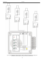
Typical application MSC1512 (fig.2, fig.3).
Fig.3. Connection of the PSU module and a 12VDC camera in an external enclosure.
EXAMPLE:
- 27V/AC power supply (e.g. PSACH04244 PSU, the output switched to U2)
- total current consumption 1,9A of AC power (by the MSC1512 module, load current: 1,5A@12V)
- L= 120m wire 2x 0,5mm2 (R= ~3Ω x2@100m)
- the voltage at the module’s terminals equals 16V/AC
- maximum power to use S= 16V*1,9A=30,4VA
- full power use MSC1512: 18W@12V/DC
2.2. Installation in a CCTV camera enclosure
1. Mount the PSU module (on the wall or inside the intended device) and lay the wires through the cable ducts.
2. Lay on the output voltage from AC transformer or DC power supply unit to the ~AC~ terminals.
3. Configure the J-Uout jumper according to the requirements of the device and the supply voltage.
4. Connect the receivers’ cables to the +AUX, -AUX terminals of the terminal strip, on the module’s pcb.
5. Switch on the AC power (the AC red diode and the AUX diode should be permanently illuminated).
6. Check the output voltage (the module’s voltage without load should amount to12V or 24V).
7. Once the tests and operation control have been completed, the enclosure can be locked.

www.pulsar.pl MSC1512
6
Fig.4. Typical application of the MSC1512 module and the PSACH04244 power supply unit.
(Conditions: camera’s power (a group of cameras) P=13W max.).

www.pulsar.pl MSC1512
7
3. Operating status indication.
The PSU is equipped with 2 LEDs that indicate operating status of: AC and AUX.
AC- red diode: Under normal status (AC power) the diode is permanently illuminated. The absence of AC
power is indicated by the AC diode going out.
AUX- green diode: indicates DC power at the module’s output. Under normal status the diode is
permanently illuminated. In case of a short circuit or an overload at the output, the diode is off.
4. Operation and use.
4.1. Overload or short circuit
In case of a short circuit at the AUX output, the output voltage is automatically cut off which is indicated by
the AUX diode going out. The voltage is restored automatically after limitation of current consumption or removing
the short circuit.
In case of an overload at the AUX output, the output voltage is automatically cut off and/or the F1 fuse
becomes damaged. Restoration of the output voltage requires limitation of current consumption or removing the
short circuit. If the fuse has been damaged, a fuse-element must be replaced.
4.2 Maintenance
The PSU module does not require performing any specific maintenance measures, however, in case of
dust, clean the surface with compressed air. In case of fuse replacement, use a replacement of the same
parameters.
WEEE MARK
According to the EU WEE Directive – It is required not to dispose of electric or electronic
waste as unsorted municipal waste and to collect such WEEE separately.
Pulsar
Siedlec 150, 32-744 Łapczyca, Poland
Tel. (+48) 14-610-19-40, Fax. (+48) 14-610-19-50
http:// www.pulsar.pl, www.zasilacze.pl
-
 1
1
-
 2
2
-
 3
3
-
 4
4
-
 5
5
-
 6
6
-
 7
7


Ask a question and I''ll find the answer in the document
Finding information in a document is now easier with AI
Related papers
-
Pulsar MSC1512 - v1.1 Operating instructions
-
-
-
-
-
-
-
-
-
Other documents
-
Legrand Universal Power Distribution Module - PW1012 Installation guide
-
 Digitsole INWS003RD4445 User manual
-
 Moticon OpenGo Instructions Manual
-
V TAC V-TAC SKU-11410 Dimmable Driver User manual
-
ThermaCELL Heated Insoles Operating instructions
-
-
ViziT BPD24/12-1-1 Operating instructions
-
Lumex LL2D23GSX User manual
-
Shimano TL-SHCFIN Dealer's Manual
-
 King gates Couper 24 User manual


