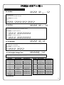
Alarm Lock AD8-PX4041 User manual
- Category
- Security access control systems
- Type
- User manual
This manual is also suitable for

1
Trilogy Series
PDL3000 Programming Instructions
WI1021 10/00© ALARM LOCK 2000
ALARM LOCK
ALARM LOCK
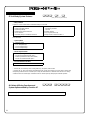
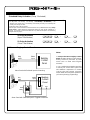
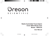
PDL3000 Trilogy Series
Standalone Access Control System
with ProxCard Access
PLUG IN THEN
ENTER YOUR CODE
HIDHID
HID CORPORATION
Prox
Card
Reader
AL-DTM (Version 1)/AL-DTM2
DATA TRANSFER MODULE
PROX CARD READER
AR-IR1 PRINTER
PROX CARD
KEYFOB

2
Features ------------------------------------------------------------------------------------------------------------------------4
Audit Trail ------------------------------------------------------------------------------------------------------------------4
User Features ------------------------------------------------------------------------------------------------------------4
User Access ---------------------------------------------------------------------------------------------------------------4
Prox Card Features -----------------------------------------------------------------------------------------------------4
500 Scheduled Events -------------------------------------------------------------------------------------------------5
Keypad and Computer Programming -------------------------------------------------------------------------------5
Accessories ------------------------------------------------------------------------------------------------------------------5
AL-IR1 Infrared Printer --------------------------------------------------------------------------------------------------5
AL-DTM2 Data Transfer Module -------------------------------------------------------------------------------------5
Prox Card Reader -------------------------------------------------------------------------------------------------------5
Additional Features ------------------------------------------------------------------------------------------------------6
Ambush Function --------------------------------------------------------------------------------------------------------6
Users Associated with more than one Group ---------------------------------------------------------------------6
Service Code -------------------------------------------------------------------------------------------------------------6
Keypad/Prox Card Lockout --------------------------------------------------------------------------------------------6
Non-Volatile Memory ----------------------------------------------------------------------------------------------------6
Error Checking -----------------------------------------------------------------------------------------------------------6
Real Time Clock ---------------------------------------------------------------------------------------------------------6
Programmable Relay Functions --------------------------------------------------------------------------------------6
Programmable Timeout Functions -----------------------------------------------------------------------------------6
Advanced Features ------------------------------------------------------------------------------------------------------6
Group 1 Initiated Functions --------------------------------------------------------------------------------------------6
Wiring and Power Up-----------------------------------------------------------------------------------------------------7
Wiring -----------------------------------------------------------------------------------------------------------------------7
Self Diagnostic Indications --------------------------------------------------------------------------------------------7
Battery Replacement ----------------------------------------------------------------------------------------------------7
Power Up - Retain Lock Programming -----------------------------------------------------------------------------7
Power Up - Erase all Programming ---------------------------------------------------------------------------------7
Preliminary Information ------------------------------------------------------------------------------------------------8
Lock Operation -----------------------------------------------------------------------------------------------------------8
Programming - Notes ---------------------------------------------------------------------------------------------------8
Programming Information ----------------------------------------------------------------------------------------------8
Visible LED and Audible Sounder Indicators ----------------------------------------------------------------------8
Getting Started -------------------------------------------------------------------------------------------------------------9
Battery Installation -------------------------------------------------------------------------------------------------------9
Entering Program Mode ------------------------------------------------------------------------------------------------9
Setting the Clock ---------------------------------------------------------------------------------------------------------9
User Programming -------------------------------------------------------------------------------------------------------10
Programming the PDL3000 for Prox Card Access ---------------------------------------------------------------10
High Security Access (Prox Card + User Code)------------------------------------------------------------------10
Deleting a Prox Card/User Code -------------------------------------------------------------------------------------11
Prox Card Batch Enroll--------------------------------------------------------------------------------------------------11
Printer Functions ----------------------------------------------------------------------------------------------------------11
Printing Time, Date and Day ------------------------------------------------------------------------------------------11
Printing User Code List -------------------------------------------------------------------------------------------------11
Printing the Audit Trail --------------------------------------------------------------------------------------------------11
Methods of Programming --------------------------------------------------------------------------------------------12
Lock Operation -------------------------------------------------------------------------------------------------------------13
Verifying User Codes ---------------------------------------------------------------------------------------------------13
Verifying Prox Card Access -------------------------------------------------------------------------------------------13
Verifying High Security Access (User Code and Prox Card ) -------------------------------------------------13
Quick Reference - Programming Functions ---------------------------------------------------------------14
Programming Functions-----------------------------------------------------------------------------------------------15

3
Function Number
1. New Master Code --------------------------------------------------------------------------------------------------------------15
2. Add/Delete/Change User Codes -----------------------------------------------------------------------------------------15
3.-4. User Enable/Disable ----------------------------------------------------------------------------------------------------------16
5. User Enable with Timeout ---------------------------------------------------------------------------------------------------16
6.-7. User Lockout Mode -----------------------------------------------------------------------------------------------------------16
9. Enable User 300 (Service Code) -----------------------------------------------------------------------------------------16
10. Erase All Users Except the Master Code ------------------------------------------------------------------------------16
12. Clear All Schedules and Timeout Functions --------------------------------------------------------------------------17
13. Clear All Timeout Functions ------------------------------------------------------------------------------------------------17
14.-23. Group Enable/Disable --------------------------------------------------------------------------------------------------------17
25.-34. Group Enable/Disable with Timeout -------------------------------------------------------------------------------------18
35. Group Add/Delete Association --------------------------------------------------------------------------------------------18
38. Set Date --------------------------------------------------------------------------------------------------------------------------19
39. Set Time --------------------------------------------------------------------------------------------------------------------------19
40. Set Weekday---------------------------------------------------------------------------------------------------------------------19
41. Set Daylight Savings Time --------------------------------------------------------------------------------------------------19
43.-44. Clock Adjust----------------------------------------------------------------------------------------------------------------------20
45.-46. Passage Mode Enable/Disable - Schedule will Override ---------------------------------------------------------20
47. Timed Passage Mode --------------------------------------------------------------------------------------------------------20
48.-50. Passage Mode Enable/Disable - Schedule will not Override ----------------------------------------------------21
51. Passage Mode Configuration ----------------------------------------------------------------------------------------------21
52.-54. Pass Time ------------------------------------------------------------------------------------------------------------------------21
55.-57. Printer Functions ---------------------------------------------------------------------------------------------------------------22
58. Upload/Download PC Data--------------------------------------------------------------------------------------------------22
59. AL-DTM2 Door Number -----------------------------------------------------------------------------------------------------23
60.-61. Lockout ----------------------------------------------------------------------------------------------------------------------------23
64.-65. Remote Input --------------------------------------------------------------------------------------------------------------------23
66. Ambush Code -------------------------------------------------------------------------------------------------------------------23
67.-68. Relay / System Features ----------------------------------------------------------------------------------------------------24
69.-70. Enter Key -------------------------------------------------------------------------------------------------------------------------25
72.-73. Scheduled Passage Mode Unlock/Lock -------------------------------------------------------------------------------25
74.-83. Scheduled Group Enable/Disable ----------------------------------------------------------------------------------------25
84.-87. Quick Schedules----------------------------------------------------------------------------------------------------------------26
88.-89. Scheduled Passage Mode - Group 1 Activated----------------------------------------------------------------------26
90.-91. Scheduled Relay Activation - Group 1 Activated---------------------------------------------------------------------27
92.-93. Scheduled Group 4 Enable - Group 1 Activated ---------------------------------------------------------------------28
99. Clear Programming -----------------------------------------------------------------------------------------------------------28
Using Advanced Features -----------------------------------------------------------------------------------------------29
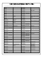
Programming Record Sheet --------------------------------------------------------------------------------------------30
User Code Record Sheet--------------------------------------------------------------------------------------------------31
Schedule Record Sheet ---------------------------------------------------------------------------------------------------32
Definitions ----------------------------------------------------------------------------------------------------------------------33
Warranty--------------------------------------------------------------------------------------------------------------------------36

4
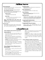
User Features
• 2000 User Codes
• Master, Installer, Manager, Supervisor, Print Only and Basic
User Codes
• 3, 4, 5 or 6 Digit User Codes
• Service Code (One-Time-Only Code)
• User Lockout Mode - Total user lockout except User 1 code
• 4 User Groups
User Access
• User Codes
• Prox Card
• Keyfob
• User Code + Prox Card (Highest Security)
Notes:
Prox Cards and Keyfobs both function the same. Keyfobs can
be replaced for all references to Prox Card.
Keypad Access and Prox Card/Keyfob Access function the
same. All references to Keypad Entry also apply to Prox Cards
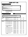
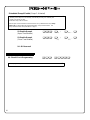
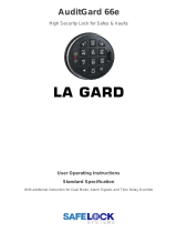
Audit Trail - 40,000 Events *
• Time/Date Stamped Log of all Entries
• Logs Program Mode changes
• View Audit Trail:
Print using the AL-IR1 hand-held printer
Upload using Alarm Lock's DL-WINDOWS Software
Use Alarm Locks AL-DTM2 to upload multiple lock logs
------- AUDIT LOG -------
08/25/00 13:06:35 Tue
13:01:59 001 PROGRAM 56
13:01:29 001 PROGRAM 57
13:00:53 001 ENTRY
13:00:26 013 ENTRY
13:00:03 012 ENTRY
12:56:27 001 PROGRAM 2
12:56:27 001 PROGRAM 40
12:56:04 001 PROGRAM 39
12:55:00 NEW CLCK TIME
12:01:39 OLD CLCK TIME
12:00:45 RAM TEST:PASS
12:00:45 POWER UP
-------------------------
End of Audit Log
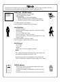
The Alarm Lock PDL3000 Series Trilogy Standalone Access Control System is a State-Of-The-Art
Microprocessor Based Programmable Keypad-Entry and PROX Security Lock.
PROX Features
• Batch Enroll - Quickly and easily enroll multiple PROX Cards/
Keyfobs without the use of a PC.
• HID PROX Compatible - compatible with most HID Prox Cards/
Keyfobs.
Compatible with 26 bit, 33 bit and 37 bit Prox Cards and Keyfobs.
HIDHID
HID CORPORATION
* AL-DTM2 transfers 5,000 events.
AL-DTM (Version 1) transfers first 1,200 events.
* AL-DTM2 transfers 2,000 User Codes.
AL-DTM (Version 1) transfer first 100 User Codes.

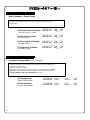
5
The Alarm Lock PDL3000 Series Trilogy Standalone Access Control System is a State-Of-The-Art
Microprocessor Based Programmable Keypad-Entry and PROX Card Security Lock.
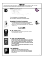
Keypad and Computer Programming
• All programming may be done manually from the keypad, or
from a PC using Alarm Lock's DL-Windows Software.
• Batch Enroll - Allows programming multiple Prox Cards without
the use of a PC.
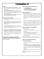
AL-DTM2 Data Transfer Module
• Optional Hand-held Data Transfer Module. The AL-DTM2 may
be used to easily transfer program data between up to 96 locks
and a PC running DL-WINDOWS software. Easily transfer
Audit Trail from multiple locks and then view or print each Audit
Trail from a computer.
• AL-DTM (version 1) may be used; however limited to 48 Locks
and the first 100 users.
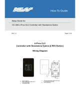
AL-IR1 Infrared Printer
• Optional hand-held infrared printer may be used to print the
Audit Trail and User Code List.
ALARM LOCK
Prox
Card
Reader
Prox Card Reader
• Optional Prox Card Reader allows quick and easy
programming of Prox Cards and Keyfobs without the need to
enter codes when using DL-WINDOWS software to program
PDL3000 locks.
500 Scheduled Events *
• Programmed to Unlock/Lock
• Enable/Disable Users
• Enable/Disable Groups
• Group 1 Activated Events
• 4 "Quick Schedules" - allows programming of the 4 most
common time schedules in one step
* AL-DTM2 transfers all 500 scheduled events.
AL-DTM (Version 1) transfer first 150 scheduled events.

6
Ambush Function
1. Connect relay to a device able to properly monitor dry
contacts for an ambush condition.
2. Program the Relay for Ambush Function Activated
using Program Function 67(10).
3. Set the Ambush Code using Program Function 66.
4. When the ambush code is entered followed by a valid
user code, the relay will close for 2 seconds.
Ambush Code
The ambush code defaults to 99.
User Code
An error will sound if you try to program a new user
code starting with the ambush code.
Users Associated with more than one
Group If a user is associated with more than one group,
all associated groups would have to be disabled before
the user is disabled.
Service Code
User number 300 is the service code. Once the service
code is used, it is disabled. Function 9 or User Number
297 is used to re-enable the service code.
Keypad Lockout
Programmable number of attempts before keypad lockout.
Programmable lockout time.
Non-Volatile Memory
All programming is stored in non-volatile memory.
Error Checking
Extensive keypad program error checking reduces the
likelihood of a programming error.
Real Time Clock
Real time clock allows logging of events to within one
second accuracy. Unique feature (Functions 43/44) allows
speeding up or slowing down the clock providing long term
accuracy of the clock functions to within 3 minutes per year.
Programmable Relay Functions
Relay may be programmed to energize when one or more
selected events occur.
Programmable Timeout Functions
Timeout functions allow enabling/disabling users and
enabling passage mode for a time period without requiring
the user to return to the lock.
Note: The alarm panel will have to be armed at night by
the user or by an automatic schedule function of
the alarm panel.
Example: Open window at 7:00AM using Program
Function 90, Close Window at 8:30AM using Function
91. The relay will close, one time only, when a member
of Group 1 enters their code between 7:00AM and
8:30AM.
Group 1 Member Enables Group 4 Users
1. Use Function 92 to set the time to open the window
allowing any Group 1 member to enable Group 4.
2. Use Function 93 to set the time to close the window.
Note: Group 4 will have to be disabled each night using
Function 17 or schedule Function 82. Example: Open
window at 7:00AM using Function 92, close window at
8:30AM using Function 93.Group 4 will be enabled when
a member of group 1 enters their code between 7:00AM
and 8:30AM (Group 4 users will have to wait outside until
a manager arrives to enable their codes. If a manager
does not arrive between 7:00AM and 8:30AM, Group 4 is
not enabled.
Group 1 Member puts unit in Passage Mode
Feature (88 & 89)
1. Use Function 88 to set an Open Time Window. The
lock will unlock (Passage Mode) when any Group 1
Member enters a code.
2. Use Function 89 to set the time to close the window.
Note: Passage Mode will have to be disabled each night
using Function 46 or schedule Function 73.
Example: Open window at 7:00AM using Function 88,
Close Window at 8:30AM using Function 89.
Lock will unlock when a member of Group 1 enters their
code between 7:00AM and 8:30AM. If no Group
1member arrives between 7:00AM and 8:30AM, the lock
will stay locked all day.
Group 1 Member Disarms Burglary Control
Panel (90 & 91)
1. Connect relay to a burglar control panel with switch
input for disarming.
2. Use Function 90 to set the time to open the window
allowing any Group 1 member to close the relay
for 2 seconds. Note: Only 1 relay closure will occur even
if another member of Group 1 enters their code.
3. Use Function 91 to set the time to close the window.

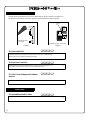
7
Wiring
Red / Black (Operation without Batteries) - Optional
External 7.5 VDC Power Source must be used for operation
without batteries.
White / White (Remote Input) - Wire a Normally Open
Contact to wires (white and white). Momentarily close to
allow person to pass through door. NOTE: Remote Input is
enabled from the factory.
Relay: COM-Blue / NO-Yellow / NC-Green - See Function
67 for programming options for the Relay.
Self Diagnostic Indications
Various system tests are performed at power up and during
operation of the lock.
Steady 4 Second Sounder with a Yellow LED indication
every time a user code is entered - Indicates a Low
Battery Condition.
Continuous Series of Beeps - Indicates the lock detected
a system fault which would not allow any part of the system
to operate. Ensure batteries are good.
Sequence of 7 Beeps Repeated 4 Times with a Yellow
LED Indication, every time a user code is entered -
indicates a non-fatal memory or clock error has been
detected. Under this condition, unexpected operation is
possible. Do not mistake the low battery indication as a
memory or clock error.
Wiring to Disarm a Burglary Control Panel
See illustration on connecting the PDL3000 to an Alarm Panel.
Scheduled Relay Activation - Group 1 Activated (Function
90/91) on on page 27.
The Three Methods of Powering Up are:
• Battery Replacement
• Power-Up Retain Lock Programming
• Power-Up Erase All Programming
Battery Replacement
When a valid code is entered and the batteries are weak the
lock LED will display a yellow color, and the sounder will
sound for 4 seconds. The PDL3000 uses 5 AA-size 1.5 volt
alkaline batteries. The lock will function with weak batteries;
however be sure to replace the batteries as soon as
possible.
Remove the screw at the bottom of the housing and remove
the cover. Pull out the battery pack and replace all 5
batteries quickly - within 1 minute. Note: Do not press any
buttons while replacing the batteries (unless lock
programming is to be erased). Pressing any key will remove
the voltage that is required to keep the system clock.
Power-Up - Retain Lock Programming
(Clock Settings lost)
1. Disconnect battery pack connector.
2. Press any key to insure the locks capacitor is fully
discharged.
3. Re-install battery pack (lock will give 3 short beeps).
4. Do not press any keys for 10 seconds.
5. After the 15 second period the LED will flash red 6 times
and 6 beeps will sound.
The lock is now ready for use. Program is loaded from non-
volatile memory. Set the clock using functions 38, 39 and 40.
Power-Up - Erase All Programming
(Factory Default will be loaded)
1. Remove the battery pack.
2. Press any key to insure locks capacitor is fully
discharged.
3. Re-install the battery pack (lock will give 3 short beeps).
4. Press any key within 5 sec after hearing the 3 beeps.
5. A series of 5 RED LED and 5 beeps will be heard
followed by 10 seconds of silence, 3 GREEN LED and 3
fast beeps.
All programming has been erased and the lock is now ready
for use.
Note: All lock programming can also be erased by entering
Function 99.

8
Lock Operation
Important: Before attempting to program any codes or
functions, Note the following:
• While the lever or knob may be rotated at any time, the latch
will not be engaged to unlock the door unless a valid code
has been entered.
• When a valid code is entered, the lock will unlock
immediately and remain unlocked for about 3 seconds (or
longer, if reprogrammed by functions 53 and 54).
Programming - Notes
It is recommended that all programming be prepared in
advance using the PDL3000 Programming Sheets for
reference while programming. User Code and Schedule
Recording sheets are provided on pages 30, 31 and 32.
Secure Programming Sheets when finished.
PROGRAM LEVELS
You must have the programming authority level equal to the
authority level required to access a programming function.
Programming authority levels can have a value of 1, 2, 3, 4 or
M. A programming authority level of M (Master) is associated
with the Master Code and cannot be associated with any other
user.
CODE TYPES
Program level ability is fixed according to table on page 15.
The codes are defaulted to the tabulated group associations
when adding codes using Program Function 2.
Master Code - User 1: Always enabled and can program all
functions, can't be group associated.
Installer Codes - Users 2 & 3: Allow all functions except
master code change.
Manager Codes - Users 4 - 6: Can program all functions
except functions relating to lock configuration, no default group
association.
Supervisors - User 7 - 9: Can only program functions relating
to day to day operation, no default group association.
Print Only Codes - Users 10 & 11: Allow access to print audit
trail only.
Basic User Codes: No program ability, default group
association.
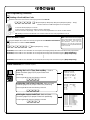
Program Level Required - The
program level required to access
the Function. Possible
Programming Levels of 1,2,3,4 and
M, where M = Master Code.
Program Authority Level of User
must be equal to the Function that
is to be accessed.
3. Disable User
; 3 ; [ _ _ _ ] :
4. Enable User
; 4 ; [ _ _ _ ] :
• User Number must be between 2 and 2000.
2
Enabling/Disabling Users (By User Number)
Programming key sequence.
Function Name
Programming
Information
If a wrong key is pressed during code entry, hold any key continuously until the error sound is heard (7 short beeps),
this will clear the entry. Re-enter the key sequence again.
General Program Mode Information
Visible LED and Audible Sounder Indicators
Normal Battery
Activity LED SOUNDER
Keypress 1 RED Flash 1 Beep
Enter Valid Enabled Code 3 GRN
Flashes
3 Beeps
Enter Invalid No/Wrong Code 6 RED Flashes 6 Beeps
Successful Program Entry 2 GRN
Flashes
2 Beeps
Unsuccessful Program Entry 7 RED Flashes 7 Beeps
Low Battery is indicated by a Yellow Flash during Key Press and a Long Beep.

9
Battery Installation
Remove the back cover and install battery pack. The lock will beep 3 times. To load the default program press any
key within 5 seconds, the lock will beep slowly while the default values are loaded and beep rapidly upon completion.
Entering Program Mode
1. Enter Master Code 1 2 3 4 5 6
Default Master Code
2. Press and hold ; until 8 beeps are sounded.
Program a new Master Code.
; 1 ; [ _ _ _ _ _ _ ] ; [ _ _ _ _ _ _ ] :
New Master Code Confirm New Master Code
Setting the Clock - While still in Program Mode enter the following commands to set the clock.
Program the Date.
; 3 8 ; [ _ _ _ _ _ _ ] :
Date
Program the Time.
; 3 9 ; [ _ _ _ _ ] :
Time
Program the Weekday.
; 4 0 ; [ _ ] :
Day
Program Daylight Saving Time.
; 4 1 ; [ _ _ ] :
For Example: To set time to 8:25 P.M.;
Enter: ; 3 9 ; 2 0 2 5 :
For Example: To set time to 8:25 A.M.;
Enter: ; 3 9 ; 0 8 2 5:
For Example: August 25, 2000;
Enter:
; 3 8 ; 0 8 2 5 0 0 :
For day enter: 1 for Sunday, 2 for Monday, 3 for Tuesday, 4 for Wednesday,
5 for Thursday, 6 for Friday and 7 for Saturday.
Program Mode
The keypad sounder will beep every 6 seconds
and the keypad LED will flash green every 6
seconds while in program mode when no keys
are pressed. NOTE: There is a 3 minute
Timeout if no keys are pressed while in
Program Mode.
For Example: To program the Default DST Mode;
Enter: ; 4 1 ; 1 2 :

10
User Programming
Add a Basic User Code
Program a User Code of 987. Use Function 2, and add the new user as User 12. Refer to Function 2 (page 15).
; 2 ; 1 2 ; 9 8 7 :
Add another Basic User Code
Program a User Code of 246. Use Function 2, and add the new user as User 13. Refer to Function 2 (page 15).
; 2 ; 1 3 ; 2 4 6 :
Programming the PDL3000 for ProxCard Access
Program the PDL3000 for ProxCard Access as User 14.
; 2 ; 1 4 : [Beep Beep Beep ... Beep]
High Security Access (ProxCard + User Code Access)
Program the PDL3000 for High Security Access for User 15. A ProxCard and User Code are required for access.
; 2 ; 1 5 : [Beep Beep Beep ... Beep]
Program a User Code of 7452. Use Function 2, and add the new user as User 15. Refer to Function 2 (page 15).
; 2 ; 1 5 ; 7 4 5 2 :
In order for User 15 to open the Lock, a User Code must be entered and a ProxCard must be presented to the PDL3000 Lock. User may enter
code or present card in either order to open the lock. The sounder will beep for up to 10 seconds, waiting for the User to enter code/present card.
User Code Conflicts
Care should be taken not to program a new user code which matches the first digits of any other user code (only the code with the
least number of digits would be recognized). Example: If user codes 123 and 123456 are both entered in the system only code 123
would be recognized, unless the ENTER Key has been enabled (Function 69).To program user codes that match the first digits of
other codes, see program Function 69. An error will sound if you try to program a new user code which matches the first digits of the
Master User Code.
User Number (12) Code for User 12
User Number (13) Code for User 13
The sounder will beep rapidly for 10
seconds. Present a CARD to the lock
while the sounder is still beeping. The
CARD is now programmed for access
by user 14.
The sounder will beep rapidly for 10
seconds. Present a CARD to the lock
while the sounder is still beeping. The
CARD is now programmed for access by
user 15.
Note: For High Security Access, the user can present the card first or
enter the CODE first. In either case the sounder will beep slowly for up to
10 seconds waiting for the user to complete the sequence.
Present CARD for User 14 within the 10-second period, the beeping
will stop after the Prox Card has been programmed.
Present CARD for User 15 within the 10-second period, the
beeping will stop after the Prox Card has been programmed.
HIHI
HIHI

11
ALARM LOCK SYSTEMS, INC
VERSION 9.00 org REC
08/25/00 13:11:28 Fri
Clock adjust setting +0
Cycle count hex 00000E
F39 day ct hex 00
Door # 01
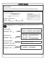
Printing the Lock’s Time, Date and Day. Refer to
Printer Functions (page 22) for proper Printer-Lock
positioning.
From Program Mode enter the following command:
; 5 7 :
User Programming (Continued)
Deleting a ProxCard/User Code
Delete ProxCard Access for the ProxCard programmed for User 12.
; 2 ; 1 2 : [Beep Beep Beep Beep Beep Beep Beep Beep Beep Beep ... Beep]
DO NOT Present a CARD during the 10-second period
The sounder will beep rapidly for 10 seconds.
DO NOT Present a CARD to the lock while the sounder is still beeping.
Wait for the Sounder to stop beeping. The ProxCard and code programmed for user 12 has now been deleted.
Note: Deleting a ProxCard associated with User 12 with also delete the User Code programmed for User 12.
ProxCard Batch Enroll
Program multiple Prox Cards successively using the PDL3000 Batch Enroll Feature.
Program 50 Prox Cards for Users 100-150.
; 2 ; 1 0 0 : [Beep Beep Beep ... Beep]
User 100 (Present CARD for User 100 within 10-second period, the beeping will stop after the ProxCard has been programmed.)
User 101 (Present CARD for User 101 within 10-second period, three beeps will sound at the keypad.) [Beep Beep Beep]
User 102 (Present CARD for User 102 within 10-second period, three beeps will sound at the keypad.) [Beep Beep Beep]
•
•
•
User 150 (Present CARD for User 150 within 10-second period, three beeps will sound at the keypad.) [Beep Beep Beep]
Printer Functions (AR-IR1 PRINTER required)
08/25/00 13:06:35 Fri
USER|USER |GROUP|PROG
NUM |CODE | |LEVL
1 123456 .... 1234
12 987 .... ....
13 246 .... ....
153 7894 .... ....
1843 2457 .... ....
Printing the Lock’s User Code List. Refer to Printer
Functions (page 22) for proper Printer-Lock positioning.
From Program Mode enter the following command:
; 5 6 :
Printing the Lock’s Audit Trail. Refer to Printer
Functions (page 22) for proper Printer-Lock positioning.
From Program Mode enter the following command:
; 5 5 :
ALARM LOCK
------- AUDIT LOG -------
08/25/00 13:06:35 Fri
13:01:59 0001 PROGRAM 56
13:01:29 0001 PROGRAM 57
13:00:53 0001 ENTRY
13:00:26 0013 ENTRY
13:00:03 0012 ENTRY
12:56:27 0001 PROGRAM 2
12:56:27 0001 PROGRAM 40
12:56:04 0001 PROGRAM 39
12:55:00 NEW CLCK TIME
12:01:39 OLD CLCK TIME
-------------------------
End of Audit Log
HIHI
HIHI
Note: Batch Enroll will not program
Users 297 through 300, these are Special
Function User Codes, See Page 15 for
more information. After a Prox Card/
Keyfob for User 296 has been Batch
Enrolled the next card presented will batch
Enroll as User 301.

12
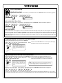
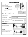
Keypad Programming
Entering Program Mode
1. Enter Master Code 1 2 3 4 5 6
Default Master Code
2. Press and hold ;
Program the Master Code
New Master Code (User Number 1)
; 1 ; [ _ _ _ _ _ _ ] ; [ _ _ _ _ _ _ ] :
New Master Code Confirm Master Code
Exiting Program Mode
There are 2 ways to exit Program Mode:
1. Hold down any key for 3 seconds
2. Press no keys for 3 minutes
(Program Mode Timeout).
ProxCard Enroll and Batch Enroll
; 2 ; [ _ _ _ _ ] :
(User Number)
Communication
The PDL3000 lock can also be programmed using a
computer with Alarm Lock's DL-WINDOWS
Software and AL-PCI cable.
“BeepBeep” “BeepBeep” “BeepBeep” “BeepBeep”
Sounder will sound 2 short beeps 4 times to indicate
the program mode is active.
Program Mode
When no keys are pressed, the keypad sounder
will beep every 6 seconds and the keypad LED
will flash green every 6 seconds. NOTE: There
is a 3 minute Program Mode Timeout if no keys
are pressed while in Program Mode. A steady
tone will sound indicating there is 15 seconds left
to press a key or Program Mode will timeout.
Tri-Color
Status LED
Infrared LED (Printer)
PC Interface/AL-DTM2
2 series of 4 Quick Beeps once
the Exit Sequence has initiated.
“BeepBeepBeepBeep” “BeepBeepBeepBeep”
The PDL3000 lock can also be programmed using Alarm
Lock's AL-DTM2 Data Transfer Module and a computer
running Alarm Lock's DL-WINDOWS Software.
AL-DTM2
Keypad will Beep for 10 seconds, present ProxCard to
PDL3000. When ProxCard has been programmed, beeping
will stop. Present additional card if desired (Batch Enroll)
HIDHID
HID CORPORATION
DL3500 Lock (mounted on door)
IBM COMPATIBLE
LAPTOP COMPUTER
TO SERIAL PORT (DB-9)
E.G. <COM 1>
AL-PCI
-
+
NOTE: Observe Tab Direction
when inserting cable into DL3500 Lock.
PDL3000 Lock (mounted on door)
PDL3000
Note:
AL-DTM2 has been
configured using a
computer running
DL-WINDOWS
software. Refer to
DL-WINDOWS
Software
documentation
OI237.
DL3500 Lock (mounted on door)
-
+
NOTE: Observe Tab Direction
when inserting cable into DL3500 Lock.
-
+
(Tab to the left)
PLUG IN THEN
ENTER YOUR CODE
AL-DTM
PDL3000 Lock (mounted on door)
PDL3000
AL-DTM2
Prox Card/Keyfob

13
Verifying Basic Keypad User Codes
Test User Code Entered in Getting Started for User 12.
Enter 9 8 7
VALID CODE - The Green LED will flash momentarily and the sounder will beep a few times after a valid code is entered.
INVALID CODE - The RED LED will flash several times and the sounder will beep several times after an invalid code is entered.
Use Function 2 to re-program the code.
Verifying Prox Card and Keyfob Access
Test Prox Card programmed for User 14 in Getting Started.
Present the Programmed Card to the PDL3000 lock
VALID CARD - The Green LED will flash momentarily and the sounder will beep a few times after a valid card or keyfob has
been presented to the PDL3000 Lock.
INVALID CARD - The RED LED will flash several times and the sounder will beep several times after an invalid card or keyfob
has been presented to the PDL3000 Lock. Use Function 2 to re-program the code.
Verifying High Security Access (ProxCard + User Code)
Test Prox Card programmed for High Security Access in Getting Started for for User 15. A ProxCard and User Code are
required for access.
1. Enter 7 4 5 2 , The sounder will beep slowly for up to 10 seconds.
2. Present the Card programmed in Getting Started to the PDL3000 Lock.
User may enter code or present card in either order to open the lock. The sounder will beep for up to 10 seconds,
waiting for the User to enter code/present card.
Note: Do not present the Prox Card and enter the User Code simultaneously.

14
For more information on PDL3000 Programming Functions see pages 15 through 28.
; 1
New Master Code
; 4 8
Enable Passage Mode
; 2
Add/Delete/Change User Codes
; 5 0
Disable Passage Mode
; 3
User Disable (By User Number)
; 4 9
Return Lock to Normal Passage
Mode Schedule
; 4
User Enable (By User Number)
; 5 1
Passage Mode Configuration
; 5
User Enable with Timeout
; 5 2 - ; 5 4
Pass Time
; 6
Enable Total User Lockout
; 5 5
Print Audit Trail
; 7
Disable Total User Lockout
; 5 6
Print User Code List
; 8
Reserved
; 5 7
Print Clock Settings and Software
Version
; 9
Enable User 300 (Service Code)
; 5 8
Upload/Download PC Data
; 1 0
Erase All Users Except the
Master Code
; 5 9
AL-DTM2 Door Number
; 1 1
Reserved
; 6 0
Number of Attempt Before Lockout
; 1 2
Clear All Schedules and Timeout
Functions
; 6 1
Set the Attempts Lockout Time
; 1 3
Clear All Timeout Functions
; 6 2 - ; 6 3
Reserved
; 1 4 - ; 1 7
Group 1-4 Disable
; 6 4 - ; 6 5
Disable/Enable Remote Input
; 1 8
Disable All Groups
; 6 6
Ambush Code
; 1 9 - ; 2 2
Group 1-4 Enable
; 6 7
Add Relay/System Features
; 2 3
Enable All Groups
; 6 8
Delete All Relay Functions and
System Options added by Function
67
; 2 4
Reserved
; 6 9 - ; 7 0
Enable/Disable Enter Key
; 2 5 - ; 2 8
Group Disable with Timeout
; 7 1
Reserved
; 2 9
Disable All Groups with Timeout
; 7 2 - ; 7 3
Scheduled Enable/Disable
Passage Mode
; 3 0 - ; 3 3
Group Enable with Timeout
; 7 4 - ; 7 7
Schedule Enable Group 1 - 4
; 3 4
Disable All Groups with Timeout
; 7 8
Schedule Enable All Groups
; 3 5
Group Add/Delete Association
; 7 9 - ; 8 2
Schedule Disable Group 1 - 4
; 3 6 - ; 3 7
Reserved
; 8 3
Schedule Disable All Groups
; 3 8
Set Date
; 8 4 - ; 8 7
Quick Schedules - Enable Group
; 3 9
Set Time
; 8 8
Passage Mode
(Open Time Window)
; 4 0
Set Weekday
; 8 9
Passage Mode
(Close Time Window)
; 4 1
Set Daylight Savings Time
; 9 0
Relay Activation
(Open Time Window)
; 4 2
Reserved
; 9 1
Relay Activation
(Close Time Window)
; 4 3
Speed Up Clock
; 9 2
Enable Group 4
(Open Time Window
; 4 4
Slow Down Clock
; 9 3
Enable Group 4
(Close Time Window
; 4 5 - ; 4 6
Passage Mode Enable/Disable
; 9 4 - ; 9 8
Reserved
; 4 7
Timed Passage Mode
; 9 9
Clear All Lock Programming

15
1. New Master Code (User Number 1)
2. Add/Delete/Change User Codes 2-2000
; 1 ; [ _ _ _ _ _ _ ] ; [ _ _ _ _ _ _ ] :
(New Master Code) (Confirm New Master Code)
Users programmed with Function 2 will default to a Group
Association and a Program Level Ability as follows:
USER TYPE USER NUMBER GROUP DEFAULT
ASSOCIATION
PROGRAM
LEVEL ABILITY
Master Code 1 - 1, 2, 3, 4, Master
Installer Codes 2 & 3 none 1, 2, 3, 4
Manager Codes 4 - 6 none 1, 2, 3
Supervisor Codes 7 - 9 none 1, 2
Print Only Codes 10 - 11 none 1
Basic User Codes 12 - 50 none none
Basic User Codes Group 1 51 - 100 1 none
Basic User Codes Group 2 101 - 150 2 none
Basic User Codes Group 3 151 - 200 3 none
Basic User Codes Group 4 201 - 250 4 none
Basic User Codes 251 - 296 none none
Quick Enable User 300 Code 297 none none
Quick PC Access Code 298 none none
AL-DTM2 Code 299 none none
Service Code 300 none none
Basic User Codes 301-2000 none none
; 2 ; [ _ _ _ _ ] * ; [ _ _ _ _ _ _ ] :
(User Number)
• User Number must be between 2 and 2000.
• To delete a code/card, leave the User Code blank and wait for the rapid beeping to stop
• User Code must be 3-6 digits.
• Deleting a ProxCard also deletes the associated User Code.
• Master Code must be 6 digits-only.
• Master Code is Keypad Code Access only, Prox Cards and Keyfobs cannot be
programmed as the Master Code.
3
M
USERS
User 299 is a Non-Pass Code. This is the only code that will initiate data transfer with the AL-DTM2.
NOTE:
* To Program ProxCard, enter
: AND Present ProxCard.

16
USERS (Continued)
; 6 :
6. Enable Total User
7. Disable Total User Lockout
; 7 :
User Lockout Mode
Enables/Disables all User Codes (Except User 1 Code) from operating the lock. Note: No other
programming functions or schedules will re-enable users. Users must be re-enabled with function 7
M
5. User Enable with Timeout
(Enter Timeout, XXX Hours)
; 5 ; [ _ _ _ _ ] ; [ _ _ _ _ ] :
(User Number) (XXX Hours)
• User Numbers must be between 2-2000.
• Hours must be between 1 - 999.
• Can override a disabled user.
2
; 1 0 ; 0 0 0 :
10. Erase All Users Except the Master
Service Code is a One-Time-Only Code. Once it is used, it is disabled until enabled again.
NOTE: User Number 297 can also be used to reset Service Code Use.
; 9 :
9. Enable User 300 (Service Code)
Erases all user codes except the Master Code (User 1).
2
M
11. Reserved
3. Disable User
; 3 ; [ _ _ _ _ ] :
(User Number)
4. Enable User
; 4 ; [ _ _ _ _ ] :
(User Number)
User Enable/Disable (By User Number)
• User Number must be between 2 and 2000.
NOTE: Will Enable/Disable users even if the user is associated with an enabled group.
2
8. Reserved

17
; 1 2 ; 0 0 0 :
12. Clear All Schedules and Timeout
; 1 3 ; 0 0 0 :
Clears all programmed Timeout Functions. Includes functions 5, 25 to 34 and Function 47.
NOTE: Only 4 Timeout Functions are allowed at any one time. An error beep will sound when
attempting to program more than 4 Timeout Functions. Scheduled/Timeout features must be manually
reset.
Clears all programmed Schedules and all Timeout Functions. Includes Schedule Functions 72 to 93.
Includes Timeout Functions 5, 25 to 34 and Function 47. NOTE: Up to 4 Timeout Functions may
be pending at any one time. An error beep will sound when attempting to program more than 4
Timeout Functions. Scheduled/Timeout features must be manually reset.
3
3
13. Clear All Timeout Functions
CLEAR FUNCTIONS
; 1 4 :
Group Enable/Disable
; 1 5 :
16. Disable Group 3
; 1 6 :
17. Disable Group 4
; 1 7 :
18. Disable All Groups
; 1 8 :
19. Enable Group 1
; 1 9 :
20. Enable Group 2 ; 2 0 :
21. Enable Group 3 ; 2 1 :
22. Enable Group 4
; 2 2 :
23. Enable All Groups
; 2 3 :
Enter the functions below to Enable/Disable Groups.
14. Disable Group 1
15. Disable Group 2
2
GROUPS
24. Reserved
1. Disabled Users
2. Enabled Groups
3. Disabled Groups
4. Enabled Users
Priority Order

18
GROUPS
; 2 5 ; [ _ _ _ ] :
(XXX Hours)
25. Timed Disable Group 1
Group Enable/Disable with Timeout (Enter Timeout, XXX Hours)
• Hours must be between 1 - 999.
Enter the functions below to Enable/Disable groups for the amount of time entered in hours.
NOTE: Only 4 Timeout Functions are allowed at any one time. An error beep will sound
when attempting to program more than 4 Timeout Functions.
2
; 3 5 ; [ _ _ _ ] ; [ _ _ _ _ ] :
(User Number) (Groups)
35. Group Add/Delete Association
• Groups that are not Selected are then Disassociated from the User (See Group Default
Association on page 15).
• User Number must be between 2 and 2000.
• 1 or more (1-4) groups to associate with user may be selected.
Add Example: To associate user 67 with groups 1, 2 and 4;
Enter: ; 3 5 ; 6 7 ; 1 2 4 :
Delete Example: To remove all group associations for user 67;
Enter: ; 3 5 ; 6 7 :
NOTE: If a user is associated with more than one group, all associated groups would have
to be disabled before the user is disabled.
; 2 6 ; [ _ _ _ ] :
(XXX Hours)
26. Timed Disable Group 2
; 2 7 ; [ _ _ _ ] :
(XXX Hours)
27. Timed Disable Group 3
; 2 8 ; [ _ _ _ ] :
(XXX Hours)
28. Timed Disable Group 4
; 2 9 ; [ _ _ _ ] :
(XXX Hours)
29. Timed Disable All Groups
; 3 0 ; [ _ _ _ ] :
(XXX Hours)
30. Timed Enable Group 1
; 3 1 ; [ _ _ _ ] :
(XXX Hours)
31. Timed Enable Group 2
; 3 2 ; [ _ _ _ ] :
(XXX Hours)
32. Timed Enable Group 3
; 3 3 ; [ _ _ _ ] :
(XXX Hours)
33. Timed Enable Group 4
; 3 4 ; [ _ _ _ ] :
(XXX Hours)
34. Timed Enable All Groups
3
36 - 37. Reserved
Clear All Timeout Functions by entering Function 13.NOTE:

19
; 3 8 ; [ _ _ _ _ _ _ ] :
(Date)
38. Set Date
42. Reserved
• Use Month Day Year format - MMDDYY - Single digit months and days are entered with
a preceding zero.
• Enter Only the last two digits of the year.
For Example: March. 8, 2000;
Enter:
; 3 8 ; 0 3 0 8 0 0 :
3
39. Set Time
; 3 9 ; [ _ _ _ _ ] :
(Time)
• Time must be 4 digits
• Use 24 Hour Format (add 12 hours to program P.M. time)
For Example: To set time to 8:25 P.M.;
Enter: ; 3 9 ; 2 0 2 5 :
For Example: To set time to 8:25 A.M.;
Enter: ; 3 9 ; 0 8 2 5 :
3
; 4 0 ; [ _ ] :
(Day)
40. Set Weekday
• For day enter: 1 for Sunday, 2 for Monday, 3 for Tuesday, 4 for Wednesday, 5 for Thursday, 6
for Friday and 7 for Saturday.
For Example: To set day to Sunday;
Enter: ; 4 0 ; 1 :
3
41. Set Daylight Savings Time
; 4 1 ; [ _ _ ] :
(DST Mode)
NOTE: Daylight Savings Time (DST) Adjustment is programmable as shown in the table below.
All modes adjust time at 2AM. * Default DST Mode is 12.
4
CLOCK SETTINGS
DST Mode Time Forwarded Time Regressed
01 No DST Adjustment
02 1st Sunday in March 4th Tuesday in Sept.
03 Last Sat. in March Last Sat. in Sept.
04 Last Sunday in March Last Sunday in Sept.
05 Last Sunday in March 4th Sunday in Oct.
06 Last Sunday in March Last Sunday in Oct.
07 Last Sunday in March 1st Sunday in Sept.
08 April 1st September 30th
09 April 1st October 1st
10 April 1st Last Sunday in Oct.
11 1st Sunday in April 2nd Sunday in Oct.
* 12 (U.S.A. &
Canada)
1st Sunday in April Last Sunday in Oct.
DST Mode Time Forwarded Time Regressed
13 Last Friday in April Last Thurs. in Sept.
14 May 1st September 30th
15 1st Sunday in Sept. 1st Sunday in April
16 2nd Tuesday in Sept. 3rd Tuesday in April
17 1st Sunday in Oct. Last Sunday in Feb.
18 1st Sunday in Oct. 3rd Sunday in March
19 1st Sunday in Oct. Last Sunday in Mar.
20 2nd Sunday in Oct. 2nd Sunday in Mar.
21 3rd Sunday in Oct. 2nd Sunday in Feb.
22 Last Sunday in Oct. 1st Sunday in March
23 Last Sunday in Oct. Last Sunday in Mar.
24 1st Sunday in Nov. Last Sunday in Feb.

20
CLOCK ADJUST
; 4 3 ; [ _ _ ] :
(seconds)
43. Speed Up Clock
; 4 4 ; [ _ _ ] :
(seconds)
44. Slow Down Clock
• Number of seconds to Speed Up/Slow Down clock each day must be 0-55 seconds.
Always consider the current setting when using this function. (Use of this function is not
cumulative.) For example, if the clock needs to be sped up 10 seconds per day and the
current setting is 10, program 20 seconds using Function 43.
Example 1: Clock is losing 13 seconds every day, enter:
; 4 3 ; 1 3 :.
This example assumes that the clock adjust setting was at the factory default of zero.
Function 57 can be used to print the current clock adjust setting.
Example 2: Clock is gaining 13 seconds every day, enter:
; 4 4 ; 1 3 :.
This example assumes that the clock adjust setting was at the factory default of zero.
Function 57 can be used to print the current clock adjust setting.
Example 3: To set the clock adjust setting back to the factory default of zero, enter:
; 4 3 : or ; 4 4 :
Clock Adjust
4
; 4 5 :
45. Enable Passage Mode
; 4 6 :
46. Disable Passage Mode
47. Timed Passage Mode
; 4 7 ; [ _ _ _ ] :
(XXX Hours)
• Allows passage through the door without the need for a code using Function 45. Re-
Lock using Function 46.
• Programmed Schedules will override the state of the lock using Functions 45 and 46. If it
is required that programmed schedules do not override passage mode, Enable/Disable
Passage Mode Enable/Disable - Schedule will Override
2
• Hours must be between 1 - 999.
Allows passage through the door without the need for a code for the programmed amount
of time.
2
PASSAGE MODE
Page is loading ...
Page is loading ...
Page is loading ...
Page is loading ...
Page is loading ...
Page is loading ...
Page is loading ...
Page is loading ...
Page is loading ...
Page is loading ...
Page is loading ...
Page is loading ...
Page is loading ...
Page is loading ...
Page is loading ...
Page is loading ...
Page is loading ...
-
 1
1
-
 2
2
-
 3
3
-
 4
4
-
 5
5
-
 6
6
-
 7
7
-
 8
8
-
 9
9
-
 10
10
-
 11
11
-
 12
12
-
 13
13
-
 14
14
-
 15
15
-
 16
16
-
 17
17
-
 18
18
-
 19
19
-
 20
20
-
 21
21
-
 22
22
-
 23
23
-
 24
24
-
 25
25
-
 26
26
-
 27
27
-
 28
28
-
 29
29
-
 30
30
-
 31
31
-
 32
32
-
 33
33
-
 34
34
-
 35
35
-
 36
36
-
 37
37


Alarm Lock AD8-PX4041 User manual
- Category
- Security access control systems
- Type
- User manual
- This manual is also suitable for
Ask a question and I''ll find the answer in the document
Finding information in a document is now easier with AI
Related papers
-
Alarm Lock T3 Prox Cheat List
-
-
-
-
-
-
-
-
-
Other documents
-
Philips 32PF1700T 32" LCD HD Ready widescreen flat TV User manual
-
LockeyUSA GE370 Operating instructions
-
 Oregon Scientific RM323A User manual
-
 Titan Controls Apollo 7 Operating instructions
-
Tork DIN100A Operating Instructions Manual
-
MESA MRX1000E User guide
-
 La Gard AuditGard 66e User Operating Instructions
-
 U-Prox U-Prox CLC Controller User guide
-
-
Buffalo 801460 User guide


