Kenmore Power Miser 12 153.320492 HT User manual
- Category
- Water heaters & boilers
- Type
- User manual

Owners
Manual
FOR POTABLEWATER
HEATING ONLY
NOT SUITABLEFOR
SPACEHEATING
Model No.
153.320392HT 30 Gal.
153.320393HT 30 Gal.
153.320492HT 40 Gal.
153.320493HT 40 Gal.
153.320592HT 50 Gal.
153.320593HT 50 Gal.
153.320692HT 66 Gal.
153.320693HT 66 Gal.
153.320892HT 80 Gal.
153.320893HT 80 Gal.
Caution:
Read and Follow
All Safety Rules and
Operating Instructions
Before First Use of
This Product.
Save this Manual for Future Reference.
POWER MISER TM 12
LECTRIC
WATER HEATER
• Safety Instructions
• Installation
• Operation
• Care and Maintenance
• Troubleshooting
• Parts List
GAMA certificationappliesto all residential electric water heaters with
capacitiesof 20 to 120Gallons. Input rating of 12Kw or less at avoltage
no greater than 250
_i,WARNING
READ THE GENERAL SAFETY SECTION BEGINNING ON INSIDE COVER
AND THEN THIS ENTIRE MANUAL BEFORE INSTALLING OR OPERAT-
ING THIS WATER HEATER.
Sears, Roebuck and Co., Hoffman Estates, IL 60179 U.S.A.

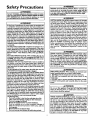
Safety Precautions
_, WARNING I
I
Improper installation, adjustment, alteration, serviceor mainte- I
nancecan causeDEATH, SERIOUS BODILY INJUI_, OR PROP-
ERTY DAMAGE. Refer to this manual for assistanceor consult
your ocal SearsService Center for further nformation.
A WARNING
At thetime ofmanufacturethiswater heaterwasprovidedwith
a combinationtemperature-pressuresreliefvalvecer_dfledbya
nationally recognizedtestinglaboratorythat maintainsperiodic
inspectionof productionof listedequipmentor materials, as
meetingthe requirementsfor ReliefValvesand AutomaticGas
ShutoffDevicesfor Hot Water SupplySystems,and the latest
editionof ANSI Z2h22 andthe cederequirementsofASME.If
replaced,the valvemust meet the requirementsoflocalcodes
but not lessthana combinationtemperatureandpressurerelief
valvecertifiedasmeetingtherequirementsfor ReliefValvesand
AutomaticGasShutoffDevicesfor Hot Water SupplySystems,
ANSI Z21.22 bya nationally recognizedtestinglaboratorythat
maintainsperiodic inspectionofproductionoflistedequipment
or materials.
The valvemust bemarkedwith a maximum setpressurenotto
exceedthe markedhydrostaticworkingpressureof the water
heater(150 Ibsdsq.in.)and adischargecapacitynotlessthanthe
water heater input rate as shownon the modelrating plate.
(Electricheaters, wattsdividedby 1000x 3415equal BTU/Hr.
rate.)
Yourlocaljurisdictionalauthority,whilemandatingthe useofa
temperature-pressurerelief valvecomplyingwith ANSI Z2h22
andASME,mayrequire avalvemodel differentfromthe onefur-
nishedwiththe waterheater.
Compliancewith suchlocalrequirements mustbe satisfiedby
the installeror enduserof thewater heaterwith a locallypre-
scribedtemperature-pressurerelief valveinstalledinthe desig-
nated openingin the water heater in placeof the factoryfur-
nishedvalve.
Forsafeoperationofthewater heater,the reliefvalvemustno_
beremovedfromit'sdesignatedopeningor plugged.
The temperature-pressurereliefvalvemust beinstalleddirectly
intothe fittingofthewater heaterdesignatedfor thereliefvalve.
Positionthe valvedownwardandprovidetubing sothat anydis-
chargewill exit onlywithin 6 inchesabove,or at any distance
belowthe structuralfloor.Be certainthat no contactismade
with anyliveelectricalpart.The dischargeopeningmustnot be
blockedor reducedin sizeunderany circumstances.Excessive
length,over 30feet,or useof more thanfour elbowscancause
restriction andreducethedischargecapacityufthe valve.
No valveor otherobstructionisto beplacedbetweentherelief
valveandthetank. Do not connecttubingdirectlyto discharge
drainunlessa 6"air gapisprovided.Topreventbodilyinjury,haz.
ardto life,or propertydamage,the reliefvalvemustbeallowed
todischargewaterinquantitiesshouldcircumstancesdemand.If I
the dischargepipeisnot connectedto a drainor othersuitabh
means,thewater flowmaycausepropertydamage.
The DischargePipe:
Mustnot be smallerinsizethantheoutletpipesizeofthe
valve,or haveanyreducingcouplingsor otherrestrictions.
Mustnot bepluggedor blocked.
Mustbeofmateriallistedfor hotwater distribution.
Must be installed so as to allow complete drainage
both the temperature-pressure relief valve, and the
dischargepipe.
Mustterminateat anadequatedrain.
Mustnot haveanyvalvebetweenthe reliefvalveandtank.
AWARNING
HAZARD OF ELECTRICAL SHOCKI Before removing any
access panels or servicing the water heater, make sure the
electrical supply to the water heater isturned "OFF". Fmluro
to do this could result in DEATH, SERIOUS BODILY INJU"
OR PROPERTY DAMAGE.
AWARNING
HOTTER WATERCAN SCALD:Water heatersare intended
to producehot water. Water heatedto a temperaturewhich
willsatisfyspaceheating,clotheswashing,dishwashing,and
other sanitizingneedscanscaldand permanentlyinjureyou
uponcontact.Somepeoplearemore likelyto bepermanent-
lyinjuredbyhotwater thanothers.Theseincludetheelderly,
children,the infirm, or physically/mentallyhandicapped.If
anyoneusing hot water in your home fits into one of these
groupsor if there isa localcodeor statelawrequiring a cer-
tain temperature water at the hot water tap, then youmust
takespecialprecautions.In additionto usingthe lowestpossi-
bletemperature settingthat satisfiesyourhot water needs,a
means suchasa mixing valve,shallbe usedat the hot water
taps usedby these people or at the water heater. Mixing
valvesare availableat plumbingsupplyor hardwarestores.
Follow manufacturers instructions for installation of the
valves.Beforechangingthe factory settingon the thermo-
stat, read the "Temperature Regulation" section in this
manual.
2
AWARNING
WATER HEATERS EQUIPPED FOR ONE VOLTAGE ONLY:
This water heater is equipped for one type voltage only.
Check the rating plate near the bottom accesspanel for the
correct voltage. DO NOT usethis water heater with any volt-
age other than the one shown on the model rating platt
Failure to use the correct voltage can cause problems which
can result in DEATH, SERIOUS BODILY INJURY, OR PROP-
ERTY DAMAGE. If you have any questions or doubts consult
your electric company.
_,WARNING
INSULATING JACKETS: When installing an external water
heater insulation jacket on an electric water heater:
a. DO NOT coverthe temperature-pressure relief valve.
b. DO NOT put insulation over the access covers or any
accessareas.
c. DO NOT cover or remove operating instructions, and safe-
ty related warning labels and materials affixed to the water
heater.
_,WARNING
Do not usethis applianceif any part of it hasbeen under
water. An electrical short or malfunction couldoccur.The
water heater shouldbereplaced.
• , CAUTION
WATER HEATERS EVENTUALLY LEAK: Installation of the
water heater must be accomplished in such a manner that if
the tank or any connections should leak, the flow of water
will not cause damage to the structure. For this reason, it is
not advisable to install the water heater in an attic or upper
floor. When such locations cannot be avoided, a suitable
drain pan should be installed under the water heater. Drain
pansare available at your oca Sears Store. Such a drain pan
must be piped to an adequate drain. Under no circumstances I
isthe manufacturer or Sears to be held liable for any water
damage in connection with this water heater.

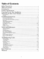
Table of Contents
_€,,,-.oal,._yPrecautions ...............................................................................................................................................2
Table of Contents ................................................................................................................................................3
Introduction ...............................................................................................................................................................4
Product
bpecihcations ..................................................................................................................................4
Preparing for the New Installation .............................................................................................4
Materials and Basic Tools Needed ...............................................................................................5
Materials Needed ...................................................................................................................................................................... 5
Basic Tools ................................................................................................................................................................................ 5
Installation Instructions ........................................................................................................................6-15
Removing the Old Water Heater ............................................................................................................................................... 6
Facts to Consider About the Location ....................................................................................................................................... 7
Facts to Consider About the Convertible Lower Element ............................................................................................. 7
Water Piping ............................................................................................................................................................................. 8
Temperature-Pressure Relief Valve............................................................................................................................................. 9
Filling the Water Heater ............ .............................. 10
Converting the Lower Element .......................................................................................................................................... 10-12
Wiring Diagrams .................................................................................................................................................................... 13
Wiring .................................................................................................................................................................................... 14
Installation Checklist .............................................................................................................................................................. 15
Service and
1 I A
Adjustment ......................................................................................................................16-20
Temperature Regulation .......................................................................................................................................................... 16
Thermostats ............................................................................................................................................................................ 16
Thermostat Settings ...................... . ........................................................... 16
Upper Thermostat Adjustment ............................................................................................................................................... 16
Lower Thermostat Adjustment ............................................................................................................................................... 17
Temperature-Pressure Relief Valve Operation .......................................................................................................................... 17
Draining ................ 17
.................. ......). ............. +*..)._
Element Cleaning and Replacement .................................................................................................................................. 18-20
Drain Valve Washer Replacement ........................................................................................................................................... 20
Service .................................................................................................................................................................................... 20
"_ " ""lroubleshooting Guide ........................................................................................................................21-24
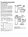
Start Up Conditions .......... . 21
Thermal Expansion ............................................................................................................................................................... 21
Strange Sounds ..................................................................................................................................................................... 21
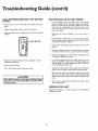
Operational Conditions ..................................................................................................................................................... 22-23
Smelly Water ......................................................................................................................................................................... 22
Air n Hot Water Faucet's..................................................................................................................................... 22
Rumbling Noise .................................................................................................................................................................... 22
High Temperature Shut Off System................................................................................................................................. 22-23
Not Enough or No Hot Water .............................................................................................................................................. 23
Water is Too Hot .................................................................................................................................................................. 23
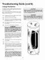
Leakage Checkpoints .............................................................................................................................................................. 24
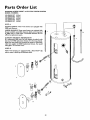
Parts Order List ...............................................................................................................................................28-31
Warranty ........................................................................................................................................................................32
3

Introduction
Thank You for purchasing a Sears water heater.
Properly installed and maintained, it should give you years of
trouble free service. If you should decide that you want the new
water beater professionally installed, contact the local Sears
Service Center or any Sears store. They will arrange for prompt,
quality installation by Sears authorized contractors.
Abbreviations Found In This Instruction Manual
U.L.-Underwriters Laboratories, 333 Pfingsten R
Northbrook, IL 60062
National Electrical Code-This publication is available from your
local government or public library or electric company or by
writing to U.L. above.
ANSI-American National Standards Institute
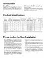
Product Specifications
MODEL
NUMBER
153.320392HT
153.320393HT
153.320492HT
153.320493HT
153.320592HT
153.320593HT
153.320692HT
153.320693HT
153.320892HT
153.320893HT
TANK
CAPACITY
IN GALLONS
30
40
50
66
80
DIMENSIONS IN INCHES
DIAMETEI HEIGHT
20 46_
20 60_
22 58_
24 61
26¼ 62
RECOVERY RATE
GALS. PER HOUR
@ 90°E RISE
17.3
25.0
17.3
25.0
17.3
25.0
17.3
25.0
17.3
25.0
ELEMENT
WATTAGE
AT 240 VOLTS
UPPER LOWER
3800 3800
3800 5500
3800 3800
3800 5500
3800 3800
3800 5500
3800 3800
3800 5500
3800 3800
3800 5500
MINIMUM
WIRE SIZE*
(GAUGE)
12
10
12
I0
12
10
12
10
12
10
MAXIMUM FUSE
OR CIRCUIT
BREAKER
SIZE (AMPS)
20
30
20
30
20
30
20
30
20
30
*Wiring size based on standard 60°C copper wire. If distance from fuse box to water heater is more than 90 feet, refer to your local electri-
cal code.
Preparing for the New Installation
• Read the "Safety Precautions" section, page 2 of this manual
first and then the entire manual carefully. If you don't follow
the safety rules, the water heater will not operate properly. It
could cause DEATH, SERIOUS BODILY INJURY
AND/OR PROPERTY DAMAGE.
This manual contains instructions for the installation, opera-
tion, and maintenance of this electric water heater. It also
contains warnings throughout the manual that you must read
and be aware or. All warnings and all instructions are essen-
tial to the proper operation of the water heater and your safe-
ty. Since we cannot put everything on the first few pages,
READ THIS ENTIRE MANUAL BEFORE ATTEMPT-
1NG TO INSTALL OR OPERATE THE WATER
HEATER.
• The installation must conform with the instructions in this
manual; electric company rules; and Local Codes, or in the
absence of Local Codes, with the latest edition of the
National Electrical Code. This publication is available from
your local government or public library or electric company
or by writing Underwriters Laboratories, 333 Pfingsten
Road, Northbrook, IL 60062.
If afrer reading this manual you have any questions or do not
understand any portion of the instructions, call Sears Service
Center.
Carefully plan the place where you are going to put the water
heater. Correct electrical wiring and connections are very
important in preventing death from possible electrical shock
and fires.
Examine the location to ensure the water heater complies with
the "Facts to Consider About the Location" section.
For California installation this water heater must be braced,
anchored, or strapped to avoid falling or moving during an
earthquake. See instructions for correct installation proce-
dures. Instructions may be obtained from your local dealer,
wholesaler, public utilities or California office of the State
Architect, 400 P Street, Sacramento, CA 95814

Materials and Basic Tools Needed
Materials Needed
To simplify the installation Sears has available the installation
parts shown below. You may or may not need all of these materi-
als, depending on your type of installation.
WATER HEATER HEAT TRAPS
HELP REDUCE HEAT LOSS DUE
TO THERMAL SYPHONING
WATER HEATER INSTALLA-
TION KIT WITH FLEXIBLE
CONNECTORS FOR 314" OR
t/2" THREADED OR COPPER
LUMBING
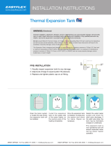
EXPANSION TANKS FOR THERMAL
EXPANSION CONDITIONS AVAILABLE
IN 2 GALLON AND 5 GALLON CAPACITY
THROUGH LOCAL SEARS SERVICE
CENTERS
DRAIN PANS AVAILABLE IN 20"
DIAMETER FOR WATER HEATERS
HAVING A DIAMETER 18" OR LESS,
24" DIAMETER FOR WATER HEATERS
HAVING A DIAMETER 22" OR LESS
AND AVAILABLE IN 28" DIAMETER
FOR WATER HEATERS HAVING A
DIAMETER 26" OR LESS
Basic Tools
You may or may not need all of these tools, depending on your
type of installation. These tools can be purchzsed at your local
Sears Stole.
Pipe Wrench (2)
Screwdriver
6 Foot Tape or Folding Rule
Garden Hose
Drill
Pipe Dope or Teflon Tape
6 FOOT TAPE
GARDEN HOSE
SLOT-HEAD SCREW DRIVER
PHILLIPS SCREWDRIVER
WRENCH
PIPE DOPE(SQUEEZE TUBE)
ROLL OF TEFLON TAPE DRILL
(Use only on water connections)
ADDITIONAL TOOLS NEEDED
WHEN SWEAT SOLDERING
Tubing Cutters or Hacksaw
Propane Torch
Soft Solder
Solder Flux
Emery Cloth
Wire Brushes
PROPANE TORCH
ROLL OF LEAD FREE
SOFT SOLDER
ROLL OF EMERY SOLDER TUBING
CLOTH FLUX CUTTER

Installation Instructions
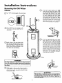
Removing the Old Water
Heater
OTurn "OFF" electrical supply to the water heater.
Q Turn "OFF" the water supply to the
water heater at the water shutoffvalve or
water meter.
QAttach a hose to the water heater drain
valve and put the other end in a floor
drain or outdoors. Open the water heater
drain valve. Open a nearby hot water
faucet which will relieve pressure in the
water heater and speed draining.
Q a. you copper piping to
If have
the
heater, the two copper water pipes can be
cut with a hacksaw approximately 4" away
from where they connect to the water
heater. This will avoid cutting off the pipes
too short. Additional cuts can be made
later if necessary. Disconnect the tempera-
ture-pressure relief valve drain line. When
the water heater is drained, disconnect the
hose from the drain valve. Close the drain
valve. The water heater is now completely
disconnected and ready to be removed.
Qb. you galvanized pipe to the water
If
have
heater, loosen the two galvanized pipe5
with a pipe wrench at the union in eadn
line. Also disconnect the piping remaining
to the water heater. These pieces should be
saved since they may be needed when
reconnecting the new water heater.
Disconnect the temperature-pressure relief
valve drain line. When the water heater is
drained, disconnect the hose from the
drain valve. Close the drain valve. The
water heater is now completely disconnect-
I ed and ready to be removed.
AWARNING [
The water passingout of the drain valvemay be extreme- J
ly hot. To avoid being scalded, make sure all connectionsI
are tight and that the water flow is directed away from
anyperson.
Q Cbeck again ,to make sure the electrical supply is
turned OFF to the water heater. Then disconnect
the electrical supply connection from the water
heater junction box.
• , CAUTION I
Mineral buildup or sediment may have accumulated in the
old water heater. This causes the water heater to be J
much heavier th.an normal and this residue, if spilled out,
could cause staining. I

Installation Instructions (cont'd)
Facts to Consider About the Facts to Consider About The
Location Convertible Lower Element
You should carefully choose an indoor location for the new
water heater, because the placement is a very important consid-
eration for the safety of the occupants in the building and for
the most economical use of the appliance. This water heater is
not intended for outdoor installation.
Whether replacing an old water heater or putting the water
heater in a new location, the following critical points must be
observed.
• The location selected should be indoors as close to and as
centralized with the water piping system as possible. This
water heater, as well as all water heaters, will eventually leak.
Do not install without adequate drainage provisions where
water flowwill cause damage.
-_ CAUTION
WATER HEATERS EVENTUALLY LEAK: Installation of
the water heater must be accomplishedin sucha manner
that if the tank or any connectionsshouldleak, the flowof
water will not cause damage to the structure. For this
reason, it isnot advisableto install the water heater in an
attic or upper floor.When suchlocationscannotbe avoid-
ed, a suitable drain pan should be installed under the
water heater. Drain pansare availableat your local Sears
stores. Such a drain pan must be piped to an adequate
drain. Under no circumstances is the manufacturer or
Searsto be held liable for any water damage in connec-
tion with this water heater.
CAUTION
INSTALLATION IN RESIDENTIAL GARAGES. The
water heater must be located and/or protected so it is
not subjectto physicaldamagebya mov ngvehcle.
The Upper Element (if a double element model), is a conven-
tional 3800 watt element which only operates at its rated
wattage on 240 volts. (See rating plate on water heater).
The Lower Element of the water heater can be converted from
operation at 3800 watts to 5500 watts on a 240 volt system.
Read and follow water heater warnings and instructions. If after
reading these instructions in this manual, if you do not under-
stand any portion, call Sears Service Center.
iI WARNING
Before making the conversionto 5500 watts, check the
(I) power supply...must be 240 volts,(2) wiring...10 gauge
AWG, Type TW, 60°C or equivalent, and (3) Circuit
breakers or fusing...capableof 30 amp loading.Also, the
installation must conform with this manual, local codes
and electric utility rules. Failure to comply can result in
DEATH. SERIOUS BODILY INJURY. OR PROPERTY
DAMAGE.
150
• The location selection must provide adequate clearances for
servicing and proper operation of the water heater.
NOTE: Whether or not the element conversion is made the
model rating plate must be marked. Using a hard point ink
pen, check the appropriate block within the model rating
plate, which is located adjacent to the lower access panel.

Installation Instructions (cont'd)
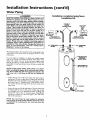
Water Piping
AWARNING
HOTTER WATER CAN SCALD: Water heaters are
intended to produce hot water. Water heated to a tem-
perature whichwill satisfyspaceheating,clotheswashing,
dish washing, and other sanitizing needs can scald and
permanently injure you upon contact. Some people are
more likelyto be permanently injured by hot water than
others. These includethe elderly, children, the infirm, or
)hysically/mentally handicapped. If anyone using hot
water in your home fits into one of these groups or
there isa local code or state law requiring a certain tem-
perature water at the hot water tap, then you must take
specialprecautions. In addition to usingthe lowest possi-
ble temperature setting that satisfies your hot water
needs, a means such as a mixing valve, shall be used at
the hot water taps used by these people or at the water
heater. Mixing valvesare available at plumbing supplyor
hardware stores. Follow manufacturers instructions for
installationof the valves.Before changingthe factory set-
ting on the thermostat, read the "Temperature
Regulation" sectionin this manual.
The illustration shows the attachment of the water pipin,_ to the
water heater. The water heater is equipped with ¾ water
connections.
If a water heater is installed in a closed water supply system;
such as one having a back-flow preventer, check valve, water
meter with a check valve, etc. in the cold water supply; means
shall be provided to control thermal expansion. Contact the
local utility or local Sears Service Center on how to control this
situation.
NOTE: If using copper robing, solder tubing to an adapter
before attaching the adapter to the cold water inlet connec-
tion. Do not solder the cold water supply line directly to the
cold water inlet. It will harm the dip tube and damage the
tank.
• Look at the top cover of the water heater. The water outlet is
marked hot. Put two or three turns of teflon tape around the
threaded end of the threaded-to-sweat coupling and around
both ends of the _" threaded nipple. Using flexible connec-
tors, connect the hot water pipe to the hot water outlet of the
water heater.
• Look at the top cover of the water heater. The cold water inlet
is marked cold. Put two or three turns of teflon tape around
the threaded end of the threaded-to-sweat coupling and
around both ends of the ¾ threaded nipple. Using flexible
connectors, connect the cold water pipe to the cold water
inlet of the water heater.
Installation completed using Sears
Installation Kit
FLEXIBLE
WATER SHUT-OFF
CONNECTORS VALVE
HOT OUTLET COLD INLET
TO HOUSE WATER LINE
THREADED TO THREADED TO
SWEAT COUPLING SWEAT COUPLING
O
TEMPERATURE-
PRESSURE
RELIEF VALVE
-- DISCHARGE PIF
(Do not cap or pk
6" AIR GAP
FLOOR DRAIN
NOTE: Your water heater is super insulated to minimize
heat loss from the tank. Further reduction in heat loss can be
accomplished by insulating the hot water lines from the
water heater.

Installation Instructions (cont'd)
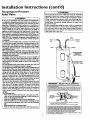
Temperature-Pressure
Relief Valve
A WARNING
At thetime ofmanufacturethiswaterheaterwasprovidedwith
a combinationtemperature-pressuresrelief valvecertifiedbya
nationallyrecognizedtestinglaboratorythat maintainsperiodic
inspectionof productionof listedequipmentor materials,as
meetingthe requirementsfor ReliefValvesandAutomaticGas
ShutoffDevicesfor Hot Water SupplySystems,and the latest
edition ofANSI Z21.22andthe coderequirementsof ASHE.If
replaced,the valvemustmeet the requirementsof localcodes
butnot lessthan a combinationtemperature andpressurerelief
valvecertifiedasmeetingthe requirementsfor ReliefValvesand
AutomaticGasShutoffDevicesfor Hot Water SupplySystems,
ANSI Z21.22 bya nationally recognizedtestinglaboratorythat
maintainsperiodicinspectionof productionof listedequipment
ormaterials.
The valvemustbe markedwith a maximum setpressurenot
to exceedthe marked hydrostaticworking pressureof the
water heater (150 Ibsdsq.in.) and a dischargecapacitynot
lessthan the water heater input rate asshownon the model
rating plate.(Electricheaters- watts dividedby 1000x 3415
equalBTU/Hr. rate,)
Yourlocaljurisdictionalauthority,whilemandatingthe useofa
temperature-pressurerelief valvecomplyingwith ANSI Z21.22
andASME,mayrequire avanemodeldifferentfromtheonefur-
nishedwith thewaterheater.
Compliancewith suchlocalrequirements must besatisfiedby
the installeror end userofthe water heaterwith a locallypre-
scribed temperature-pressurerelief valveinstalledin the desig-
natedopeningin the water heaterin placeof the factoryfur-
nishedvalve.
Forsafeoperationofthe waterheater,thereliefvalvemustnot
beremovedfromit'sdesignatedopeningor plugged.
The temperature-pressurereliefvalvemustbe installeddirectly
intothefittingofthe water heaterdesignatedforthe reliefvalve.
Positionthe valvedownwardand providetubing sothat anydis-
chargewillexit onlywithin 6 inchesabove,or at any distance
belowthe structuralfloor.Be certainthat no contactismade
with anyliveelectricalpart.The dischargeopeningmustnot be
blockedor reduced in sizeunderanycircumstances. Excessive
length,over30feet,or useof morethan fourelbowscancause
restriction andreducethedischargecapacityofthe valve.
No valveor otherobstructionisto beplacedbetweenthe relief
valveandthe tank.Do not connecttubingdirectlyto discharge
drainunlessa 6" air gapisprovided.To preventbodilyinjury,
hazardto life,or property damage,the relief valvemust be
allowedto dischargewater in quantitiesshouldcircumstances
demand.If the dischargepipeisnot connectedto a drainor
i other suitable means,the water flow may causeproperty
damage.
:The DischargePipe:
: Mustnot be smallerinsizethan the outlet pipesizeofthe
valve,or haveanyreducing couplingsor other restrictions.
Mustnot be pluggedor blocked.
• Mustbe ofmateriallistedfor hotwater distribution.
! Mustbe installedsoasto allow completedrainageof both
the temperature-pressurerelief valve,and the discharge
pipe.
t Mustterminate at anadequatedrain.
Mustnot haveanyvalvebetween the rolief valveandtank.
&WARNING
The temperature-pressure relief valve must be manually
operated at leastonce a year. Caution shouldbe taken to
ensurethat (I) no one is in front of or around the outlet
of the temperature-pressure relief valve discharge line,
and (2) the water manually dischargedwill not causeany
bodilyinjury or property damage becausethe water may
be extremely hot.
If after manually operating the valve, it failsto completely
reset and continues to release water, immediately, close
the coldwater inlet to the water heater,follow the drain-
ing instructions, and replace the temperature-pressure
relief valvewith a newone.
HOT
.TEMPERATURE-
PRESSURE
RELIEF VALVE
(Do not cap or plug)
6" AIR GAP
FLOOR DRAIN
T&P RELIEF
VALVEPROBE
INTO TANK
TEMPERATURE-
PRESSURE
RELIEF VALVE
T&P
SHANK
NIPPLE ' ' ' LENGTH
• If a shor_shank (le_s than 2") temperature-pressureielie$valve isto be installed
(as shown),a nippleand couplingmust _ used
• _fa longshank(2" or longer)isto be inst_led,de not use thenipple and co_ng
InStallTemperalu_ePressurep_otectNeeou_nent_quired by_c_.aleodes,b_ notlessthana comb+ha.
bo,, Temperature Pressure Relief Valve certified as meeting the requi;ements for Relief Valves and
AutomaticGasShutoff_ 1o'Hot-water Supd.ySystems¸A_S 72122by _ na_0nally_ecc_zed test.
mglab_aton/that _ periodc_specaca ofpn:ducbt_olIm_:l equprnemor marshalsTheva;ve
rn_ beode_l_, pmV,ded _€_hM:ing, c<_ mstal_d soI_ d_so3an_ecanexatonlyw_n 6 _ch_s
above,ot atanydistancebelowB-,as_tural IIo_, andcannotcontactanyliveelectricalpa_
Forsaleope_on c+If_ wate_heater,the gekefValvem_str,_ bet_',o_d or p_gge¢
See rnar_Jalheading- Temperatule-pressureRel+elValve for installal_ona_ maintenanceof Relief
Valve¸clschargepipeandc6_etsafetypre_ubor,s
9

Installation Instructions (cont'd)
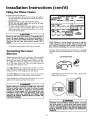
Filling the Water Heater
To fill the water hearer with water:
• Close the water heater drain valve by turning the handle to
the right (clockwise). The drain valve is on the lower front of
the water hearer.
Open the cold water supply valve to the water heater.
NOTE: The cold water supply valve must be left open
when the water heater is in use.
To insure complete filling of the tank, allow air to exit by
opening the nearest hot water faucet. Allow water to run
until a constant flow is obtained. This will let air out of the
water heater and the piping.
A CAUTION
Never usethis water heater unlessit iscompletely full of
water. To prevent damage to the tank and heating ele-
ment, the tank must be filled with water. Water must
flow from the hot water faucet before turning "ON"
power.
Check all new water piping for leaks. Repair as needed.
Converting the Lower
Element
NOTE: Whether or not the element conversion is made the
model rating plate must be marked. Using a haxdpoint ink
pen, check the appropriate block within the model rating
plate, which is located adjacent to the lower access panel.
Necessary element conversion parts are located in a small bag
contained within the electrical junction box on top of the water
heater.
These instructions only cover the conversion of the convertible
element, read this entire manual before attempting to install or
operate the water heater. The water heater is factory set to oper-
ate at 3800 watts. The lower element can be converted to oper-
ate at 5500 watts. Refer to the "Facts to Consider About the
Convertible Lower Element" section.
The Upper Element, (if a double element model) is a conven-
tional 3800 watt element which only operates at its rated
wattage on 240 volts, (See rating plate on water heater).
The Lower Element of the water heater can be converted from
operation at 3800 watts to 5500 watts on a 240 volt system.
If after reading these instructions and this manual, if you do not
understand any portion, call Sears Service Center.
CONVERSION PARTS
BUSS BAR
I. Before beginning the conversion turn "OFF" electric power
supply to the water heater.
AWARNING
Before making the conversion to 5500 watts, check the
(I) power supply...mustbe 240 volts, (2) wiring...10 gauge
AWG, Type TW, 60°C or equivalent, and (3) Circuit
breakers or fusing...capableof 30 amp loading. Also, the
installation must conform with this Manual, local codes
and electric utility rules. FAILURE TO COMPLY CAN
RESULT IN DEATH, SERIOUS BODILY INJURY OR
PROPERTY DAMAGE.
AWARNING
HAZARD OF ELECTRICAL SHOCK! Before removing
any access panels or servicing the water heaterp make
sure the electrical supply to the water heater is turned
"OFF". FAILURE TO DO THIS COULD RESULT IN
DEATH, SERIOUS BODILY INJURY, OR PROPERTY
I DAMAGE.
10

Installation Instructions (cont'd)
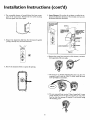
2. The convertible element is located behind the lower access
panel of the water heater. Remove the two screws securing
the access panel, and remove panel.
5. Lower Element: LiE out the tab as shown to unclip the ter-
minal cover from the thermostat. The terminal cover can now
be removed from the thermostat.
3. Remove the adjustment dial from the thermostat by gently
pulling it directly away from the thermostat.
4. Remove the insulation block to expose the opening.
Lift out tab to until!
ternllnaJ cover from
t_ermosta_
,AC
TERMINAL COVER
CLIPPED TO THER-
P"O%?TATTH's
PLASTIC TABS ON
'BOTH SIDES OF
TERMINAL COVER
HOLD IT IN
PLACE.
THERMOSTAT
BRACKET
q(--- TANK
_LEMENT
6. Remove the screws from terminal 2 of the element, and move
the looped end of the wire aside.
7. The buss bar is labeled 5500 W. Place the buss bar over
terminals 2 and 3 with the 5500 W visible. Install the extra
screw provided into terminal 3.
8. The wire removed from terminal 2 has a looped end. It must
remain looped and now be placed (as shown) on top of the
buss bar, over the opening of terminal 2, and secured using
the remaining screw.
11

Installation Instructions (cont'd)
Converting the Lower
Element (cont'd)
9. Tighten terminals 2 and 3 to ensure proper electrical
connection.
AWARNING_
Failure to lighten terminal screws can cause a fire which
can result in DEATH, SERIOUS BODILY INJURY, OR I
PROPERTY DAMAGE. 1
10. Replace terminal cover on the thermostat, making sure the
notch is in place over the tab.
12. The adjustment dial has a "D" shaped opening that matches
a "D" shaped shaft on the thermostat. Align the opening in
the dial to the shaft and gently push the dial onto the shaft.
13. Replace the access panel.
AWARNING
Make sure the thermostat is flush against the tank, the
terminal cover is in place, and the insulation is replaced.
Failure to do so can result in DEATH, SERIOUS BODILY
NJURY, OR PROPERTY DAMAGE.
l 1. Replace the insulation block so that it completely covers the
thermostat and element.
14. Complete wiring to the water heater, or if completed, turn
"ON" electric power to the water heater after filling the
tank with water.
A CAUTION
Never use this water heater unless it is completely full ofl
water. To prevent damage to the tank and heating ele-
ment, the tank must be filled with water. Water must J
flow from the hot water faucet before turning "ON"
power. I
12

Installation Instructions (cont'd)
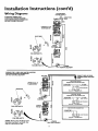
Wiring Diagrams
STANDARD WIRING FOR
2 WIRE LEAD WATER HEATERS
NON.SIMULTANEOUS OPERATION
240 VOLT DOUBLE ELEMENT
TO ELECTRIC
POWER SUPPLY
LJNCTION
BLACK
RED
UPPER E.C,O. &
THERMOSTAT
BUSS BAR _O
\ °
_ a
FOR 5500 WATTS
UPPER-"
ELEMENT
EOR3800W=" ENT
WIRING FOR 3 WIRE LEAD WATER HEATERS
NON-SIMULTANEOUS OPERATION
240 VOLT DOUBLE ELEMENT
UPPER E.C.O. &
THERMOSTAT
BUSS BAR
FOR 5500 WATTS
FOR 3800 WATTS
ELEMENT
LOWER
T'STAT
LOWER
HEATING ELEMENT
THREE TYPES OF FIELD
t ONNECTIONS YOU MAY
HAVE
TIME CLOCK SWITCH
OPERATES BOTTOM ELEMENT ONLY
TO ELECTRIC _ L2 _ TO TIME
POWER SUPPLY L[ L2 L2 CLOCK SWITCH
JWL_BI A NCTION BOX
YELLO CK
"OFF PEAK" METER
OPERATES BOTTOM ELEMENT ONLY
TO ELECTRIC *_--r_L2LIL2 -'P TO "OFF
POWERSUPPLY Li _ PEAK'METER
IUNCTION BOX
YELLO LACK
FOR TWO WIRE CONNECTION
TO ELECTRIC
POWER SUPPLY
LI L2
OW_J UNCTION BOX
YELL _CK
*NOTE: Some Lower Hi-Temp Limit
Switches may have 4 terminals. Use
onlythe 2 terminals on left.
13

Installation Instructions (cont'd)
Wiring
A CAUTION I
Never use this water heater unless it is completely full of
water. To prevent damage to the tank and heating ele-
ment, the tank must be filled with water. Water must
flow from the hot water faucet before turning on power.
You must provide all wiring of the proper size outside of the
water heater. You must obey local codes and electric company
requirements when you install this wiring.
If you are not familiar with electric codes and practices, or if you
have any doubt, even the slightest doubt, in your ability to con-
nect the wiring to this water heater, obtain the service of a com-
petent electrician. Contact your Sears salesperson to arrange for
a professional electrician.
C. Flexible metal conduit or flexible metallic tubing shall be
permitted for grounding if all the following conditions are
met:
1. The length in any ground return path does not exceed
6 feet.
2. The circuit conductors contained therein are protected
by overcurrent devices rated at 20 amperes or less.
3. The conduit or tubing is terminated in fittings
approved for grounding.
For complete grounding details and all allowable exceptions,
refer to the latest edition of the National Electrical Code.
4. A standard _" conduit opening has been made in the water
heater junction box for the conduit connection.
AWARNING
WATER HEATERS EQUIPPED FOR ONE VOLTAGE
ONLY: This water heater isequippedfor one type voltage
only.Check the rating plate near the bottom accesspanel
for the correct voltage. DO NOT use this water heater
with anyvoltage other than the one shownon the model
rating plate. Failure to usethe correct voltagecan cause
problems which can result in DEATH SERIOUS BODILY
NJURY,OR PROPERTY DAMAGE. If you have anyques-
tionsor doubtsconsultyour electric company.
A CAUTION
If wiring from your fuse box or circuit breaker box was
aluminum for your old water heater, replace it with cop-
per wire. If you wish to reuse the existing aluminum wire,
have the connection at the water heater made by a com-
petent electrician. Contact your Sears salesperson to
arrange for a professional electrician.
1. Provide a way to easily shut off the electric power when work-
ing on the water heater. This could be with a circuit breaker
or fuse block in the entrance box or a separate disconnect
switch.
2. Install and connect a circuit directly from the main fuse or
circuit breaker box. This circuit must be the right size and
have its own fuse or circuit breaker. Refer to the chart in the
"Product Specifications" section for the correct size wire and
fuse or circuit breaker.
5.
6.
7.
Wiring Diagrams (See Wiring Diagrams Section) have been
supplied showing the two most common types of connec-
tions between the water heater and the power supply. You can
easily see which type connection you have by removing the
junction box cover on top of the water heater.
A. Two Wire Connection Diagrams: is the most common
requiring you to simply connect red to red, black to black,
and the ground wire to the green ground screw in the junc-
tion box of the water heater.
B. Three Wire Connection Diagram: is used when you aa
connecting the water heater to power a supply that has a
"T'me Clock" or Off Peak Meter. To make these connec-
tions refer to block 1 or 2 in this wiring diagram for the type
of system you have.
NOTE: If you have purchased a three wire connection
water heater but you are not on a "Time Clock" or "Off
Peak" meter and have a standard two wire connection
lower supply, simply follow the connection diagram in
lock 3. of the Three Wire Connection Diagram.
Use wire nuts and connect the power supply wiring to the
wires ins'de the water heaters junction.
The water heater must be electrically "grounded" by the
installer. A green ground screw has been provided on the
water heater's junction box. Connect ground wire to this
location.
8. Replace the wiring junction cover using the screw provided.
3. If metal conduit is used for the grounding conductor:
A. The grounding electrode conductor shall be of copper,
aluminum, or copperclad aluminum. The material shall
be of one continuous length without a splice or joint.
B. Rigid metal conduit, intermediate metal conduit, or elec-
trical metallic tubing may be used for the grounding
means if conduit or tubing is terminated in fittings
approved for grounding.
CONDUIT
'GREEN
SCREW
14

Installation Instructions (cont'd)
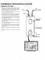
Installation Checklist
Whether or not the element conversion is made, the model
rating plate must be marked. Using a hard point ink pen,
check the appropriate block within the model rating plate,
which is located adjacent to the lower access panel.
Is the fuse or circuit breaker size correct as shown in the chart
in the "Product Specifications" section?
Are the wires from the circuit breaker or fuse service to the
water heater's junction box on the correct wire size (gauge) as
shown in the chart m the Product Speclficauons section.
Is the new temperature-pressure relief valve properly
installed, and piped to an adequate drain? See "Temperature-
Pressure Relief Valve" section.
ls the water heater completely filled with water? See "Filling
the Water Heater" instructions in the "Installation
Instructions" section.
Will a water leak damage anything? See "Facts to Consider
About the Location sectmn.
Are the cold and hot water lines connected to the water heater
correctly? See "Water Piping" instructions in the "Installation
Instructions" section.
Is there adequate clearance for maintenance around the water
heater?
Do you need to call your electric company to check your
wiring?
HOT COLD
TEMPERATURE-
PRESSURE
RELIEFVALVE
_DISCHARGE PIPE
(Do notcap or plug)
I6 AIR GAP
De
FLOOR DRAIN
MODEL RATING PLATE
15

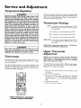
Service and Adjustment
Temperature Regulation
A WARNING
HOTTER WATER CAN SCALD: Water heaters are
intended to produce hot water. Water heated to a tem-
perature whichwill satisfyspaceheating,clotheswashing,
dish washing, and other sanitizing needs can scald and
permanently injure you upon contact. Some people are
more likely to be permanently injured by hot water than
others. These includethe elderly, children,the infirm, or
physically/mentally handicapped. If anyone using hot
water in your home fits into one of these groups or if
there isa localcode or state law requiring a certain tem-
perature water at the hot water tap, then you must take
specialprecautions. In addition to usingthe lowest possi-
ble temperature setting that satisfies your hot water
needs, a means suchas a mixing valve, shallbe used at
the hot water taps used by these people or at the water
heater. Mixing valvesare available at plumbing supplyor
hardware stores. Follow manufacturers instructions for
installationof the valves.Before changingthe factory set-
ting on the thermostat, read the "Temperature
Regulation"sectionin this manual.
The lower thermostat is factory set at its lowest position which
approximates 120°F (Hot) and is adjustable if a different water
temperature is desired. Read all warnings in this manual and on
the water heater before proceeding.
Temperature Settings
HOT-Is a thermostat setting of approximately 120°F,
which will supply hot water at the most economi-
ca] temperatures.
A-Is a thermostat setting of approximately 130°E
B-Is a thermostat setting of approximately 140°E
C-Is a thermostat setting of approximately 150°E
VERY HOT-Is a thermostat setting of approximately 160°E It
is recommended that the dial be set lower when-
ever possible.
AWARNING ]
Never allow small children to use a hot water tap, or to|
draw their own bath water. Never leave a child or handi-|
capped person unattended in a bathtub or shower. ]
Thermostats
The thermostat(s) of this water heater have been factory set at
their lowest position which approximates 120°F (Hot) to reduce
the risk of scald injury.
The upper thermostat is factory set at its lowest position which
approximates 120°F (Hot) and is adjustable if a different water
temperature is desired. Read all warnings in this manual and on
the water heater before proceeding.
4
OI
NOTE: Water temperature range of 120°--140°F recom-
mended by most dishwasher manufacturers.
Upper Thermostat
Adjustment
NOTE: It is not necessary to adjust the upper thermostat.
However, if it is adjusted above the factory set point of
120°F (HOT) it is recommended that it not be set higher
than the lower thermostat setting.
The upper thermostat is adjustable if a different water tempera-
ture is desired. Read all warnings in the "Temperature-
Regulation" section before proceeding.
1. Turn "OFF" the electrical power to the water heater at the
junction box.
2. Take "OFF" the access panel.
3. The slotted adjustment (using a screwdriver) can be turned
clockwise (___.J) to increase the temperature setting or
counter clockwise (k.._.._) to decrease the temperature set-
tmg.
4. Replace the access panel.
5. Turn "ON" the power supply.
UPPER THERMOSTAT ADJUSTABLE
BEHIND UPPER ACCESS PANEL
16

Service and Adjustment (cont'd)
Lower Thermostat
Adjustment
The lower thermostat is adjustable if a different water tempera-
ture is desired. Read all warnings in the "Temperature-
Regulation' section before proceed'ng.
Failure to install and maintain a new properly listed tempera-
ture-pressure relief valve will release the manufacturer from any
claim which might result from excessive temperature or pressure.
The adjustment dial can be turned clockwise (_...J) to
increase the temperature setting or counter clockwise to
( _ ) decrease the temperature setting.
A WARNING
If the temperature-pressure relief valve on the appliance
weeps or discharges periodically, this may be due to ther-
mal expansion. Your water heater may have a check valve
installed in the water line or a water meter with a check
valve. Consult your local Sears Service Center for further
information. Do not plug the temperature-pressure relief
valve.
Draining
LOWER THERMOSTAT ADJUSTABLE
THROUGH LOWER ACCESS PANEL
Temperature-Pressure Relief
Valve Operation
The temperature-pressure relief valve must be manually operated
at least once a year.
TEMPERATURE-PRESSURE
RELIEFVALVE
DISCHARGE PIPE
AWARNING
The temperature-pressure relief valve must be manually
operated at least once a year. Caution should be taken to
ensure that (I) no one is in front of or around the outlet of
the temperature-pressure relief valve discharge line, and (2)
the water manually discharged will not cause any property
damage or bodily injury. The water may be extremely hot.
If after manually operating the valve, it fails to completely
reset and continues to release water, immediately close the
cold water inlet to the water heater, follow the draining
instructions, and replace the temperature-pressure relief
valve with a new one.
The water heater should be drained if being shut down during
freezing temperatures. Also periodic draining and cleaning of
sediment from the tank may be necessary.
• Before beginning turn "OFF" the electric power supply to the
water heater.
AWARNING I
HAZARD OF ELECTRICAL SHOCK! Before removing I
any access panels or servicing the water heater, make
sure the electrical supply to the water heater is turned I
"OFF". Failure to do this could result in DEATH, SERI-
OUS BODILY INJURY, OR PROPERTY DAMAGE.
• CLOSE the cold water inlet valve to the water heater.
• OPEN a nearby hot water faucet and leave open to allow for
draining.
• Connect a hose to the drain valve and terminate to an
adequate drain or outdoors.
• OPEN the water heater drain valve to allow for tank draining.
NOTE: If the water heater is going to be shut down and
drained for an extended period, the drain valve should be
left open with hose connected allowing water to terminate
to an adequate drain.
• Close the drain valve.
• Follow "Filling the Water Heater" instructions in the
Installat on Instrucnons secnon.
• Turn "ON" power to the water heater.
A CAUTION I
N_.ver use this water heater unless it is completely full I
water. To prevent damage to the tank and heating ele-
ment, the tank must be filled with water. Water must I
flow from the hot water faucet before turning "ON"
power.
17

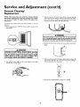
Service and Adjustment (cont'd)
Element Cleaning/
Replacement
NOTE: These instructions are written for element cleaning
and element replacement for the lower element. If it is neces-
sary to dean or replace the upper element, then repeat these
instructions.
3. Attach a hose to the water heater drain valve and put the
other end in a floor drain or outdoors. Open the water heater
drain valve. Open a nearby hot water faucet which will relieve
pressure in the water heater and speed draining.
To remove the element from your tank in order to clean or
replace it:
1. Before beginning turn "OFF" the electric power supply to the
water heater.
AWARNING
HAZARD OF ELECTRICAL SHOCK! Before removing I
any access panels or servicing the water heater, make I
sure the electrical supply to the water heater is turned]
"OFF". Failure to do this could result in DEATH, SERI- I
OUS BODILY INJURY, OR PROPERTY DAMAGE. |
2. Turn off the water supply to the water heater at the water
shutoffvalve or water meter.
AWARNING ]
The water passingout of the drainvalvemay be extremely]
hot.Toavoidbeingscalded,makesureallconnectionsaretight
andthat the waterflowisdirectedawayfromanyperson.
4. Remove the two screws securing the access panel, and remove
panel.
5. After you have removed the lower access panel, remove the
adjustment dial from the thermostat by gently pulling it
directly away from the thermostat.
6. Remove the insulation block to expose the opening.
18

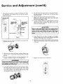
Service and Adjustment (cont'd)
7. Lift out the tab as shown to unclip the terminal cover from
the thermostat. The terminal cover can now be removed
from the thermostat.
Lif_ out tab to uncli F
terminal ¢Gver from
I_ ernl°stat"
TERMINAL COVER
CLIPPED TO THER-
+ATT"'s
LOWER THERMOSTAT
PLASTIC TABS ON
'BOTH SIDES OF
TERMINAL COVER
HOLD IT IN
PLACE,
THERMOSTAT
BRACKET
,ill-- TAN K
-ELEMENT
8. Disconnect the two wires on the element and unscrew the
old element from the tank.
12. Close the water heater drain valve by turning the handle to
the right (clockwise). The drain valve is on the lower front
of the water heater.
13. Open the cold water supply valve to the water heater.
NOTE: The cold water supply valve must be left open
when the water heater is in use.
14. To insure complete filling of the tank, allow air to exit by
opening the nearest hot water faucet. Allow water to run
until a constant flow is obtained. This will let air out of the
water heater and the piping.
A CAUTION
Never usethis water heater unlessit iscompletely full of I
water. To prevent damage to the tank and heating ele- I
ment, the tank must be filled with water. Water must I
flow from the hot water faucet before turning "ON"
power.
15. Check element for water leaks. If leakage occurs, tighten
element or repeat steps 2 and 3, remove element and reposi-
tion gasket. Then repeat steps 11 through 15.
16. Reconnect the two wires to the element and then check to
make sure the thermostat remains firmly against the surface
of the tank.
9. Clean the area around the element opening. Remove any
sediment from or around the element opening and inside
the tank.
10. lfyou are cleaning the element you have removed, do so by
scraping or soaking in vinegar or a de-liming solution.
AWARNING 1
Replacement elements must (I) be the samevoltage and
(2) no greater wattage than listed on the model rating
p ate affixedto the water heater.
11. A new gasket should be used in all cases to prevent a possi-
ble water leak. (See Element Gasket in the Parts Order
List" Chart). Place the new element gasket on the thread
side of the cleaned or new element and screw into tank,
securing tightly using an element wrench.
17. Replace the terminal cover on thermostat.
19

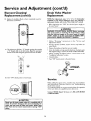
Service and Adjustment (cont'd)
Element Cleaning/
Replacement (cont'd)
18. Replace the insulation block so that it completely covers the
thermostat and element.
19. The adjustment dial has a "D" shaped opening that matches
a D shaped shaft on the thermostat. Align the opening in
the dial to the shaft and gently push the dial onto the shaft.
j
20. Turn "ON" electric power to water heater.
Drain Valve Washer
Replacement
NOTE: For replacement, use a '%/' x _" x %" thick washer
available at your nearest hardware store. For ordering a
replacement washer, refer to the "Parts Order List" section.
• Before beginning turn "OFF" the electrical power supply to
the waterbeater.
AWARNING
HAZARD OF ELECTRICAL SHOCK! Before removing
any access panels or servicing the water heater, make
sure the electrical supply to the water heater is turned I
"OFF". Failure to do this could result in DEATH, SERI-
OUS BOD LYINJURY,OR PROPERTY DAMAGE.
• Follow "Draining" instructions in the "Service and
Adjustment" section.
• Turning counter clockwise, remove the hex cap below the
screw handle.
• Remove the washer and put the new one in place.
• Screw the handle and cap assembly back into the drain valve
and retighten using a wrench. DO NOT OVER TIGHTEN.
• Follow "Filling the Water Heater" instructions in the
"Installation Instructions" section.
• Check for leaks.
• Turn "ON" electric power to the water heater.
_ HANDLE AND
)._ CAP ASSEMBLY
_ WASHER
Service
Before calling for repair service, read the Start Up Conditions
and Operational Conditions found in the Troubleshooting
Guide of this manual.
If a condition persists or you are uncertain about the operation
of the water heater, let a qualified person check it out.
Contact SEARS Repair Services at 1-800-4-MY-HOME
(1-800-469-4663).
A CAUTION [
Never usethis water heater unlessit iscompletely full of]
water. To prevent damage to the tank and heating ele- I
ment, the tank must be filled with water. Water must I
flow from the hot water faucet before turning "ON"
power.
2O
Page is loading ...
Page is loading ...
Page is loading ...
Page is loading ...
Page is loading ...
Page is loading ...
Page is loading ...
Page is loading ...
Page is loading ...
Page is loading ...
Page is loading ...
Page is loading ...
-
 1
1
-
 2
2
-
 3
3
-
 4
4
-
 5
5
-
 6
6
-
 7
7
-
 8
8
-
 9
9
-
 10
10
-
 11
11
-
 12
12
-
 13
13
-
 14
14
-
 15
15
-
 16
16
-
 17
17
-
 18
18
-
 19
19
-
 20
20
-
 21
21
-
 22
22
-
 23
23
-
 24
24
-
 25
25
-
 26
26
-
 27
27
-
 28
28
-
 29
29
-
 30
30
-
 31
31
-
 32
32


Kenmore Power Miser 12 153.320492 HT User manual
- Category
- Water heaters & boilers
- Type
- User manual
Ask a question and I''ll find the answer in the document
Finding information in a document is now easier with AI
Related papers
-
Kenmore 153.31206 User manual
-
-
Sears 53.329563 POWER MISER 9 153.329662 User manual
-
-
-
-
-
-
Sears 153.326562 55 GAL. User manual
-