Maytag HE21250PC User manual
- Category
- Water heaters & boilers
- Type
- User manual
This manual is also suitable for

IVIAYIAG
Series Twelve PC
INTELLIGENTELECTRIC
WATER HEATER _o_, Numbers
USER'SGUIDE _:_0_
FOR POTABLE WATER
HEATING ONLY
GAMA certification applies to all residential
electric water heaters with capacities of 20 to NOT SUITABLEFOR
120 Gallons. Input rating of 12 Kw or lessat a SPACE HEATING
voltage no greater than 250 V.
Caution:
AWARNING Read and Follow All
READ THE GENERAL SAFETY SECTION BEGINNING ON INSIDE Safety Rules and
COVERAND THENTHIS ENTIREMANUAL BEFOREINSTALLINGOR Operating Instructions
OPERATINGTHISWATERHEATER. Before First Use of
Save this Manual for Future Reference. This Product.

Safety Instructions
Improper installation, adjustment, alteration, service |At the time of manufacture this water heater was pro-|
or maintenance can cause DEATH, SERIOUS BODILY |vided with a combination temperature-pressures relief |
INJURY,OR PROPERTYDAMAGE. Refer to this manu- /valve certified by a nationally recognized testing labora-
al for assistance consult your local utility or call tory that maintains periodic inspection of production of
Maytag Customer Service at 1-800-788-8899 for an listed equipment or materials, as meeting the require-
authorized servicer for further information, ments for Relief Valves and Automatic Gas Shutoff
Devices for Hot Water Supply Systems, and the latest
edition of ANSI Z21.22 andthe code requirements of
ASME. If replaced, the valve must meet the require-
ments of local codes, but not lessthan a combination
_, WARNING
temperature and pressurerelief valve certified as meet-
HAZARD OF ELECTRICAL SHOCK! Before removing ing the requirements for Relief Valves and Automatic
any access panels or servicing the water heater, GasShutoff Devicesfor Hot Water Supply Systems,ANSI
make sure the electrical supply to the water heater Z21.22 by a nationally recognized testing laboratory
is turned "OFF". Failure to do this could result in that maintains periodic inspection of production of list-
DEATH, SERIOUS BODILY INJURY, OR PROPERTY ed equipment or materials.
DAMAGE. The valve must be marked with a maximum set pressure
not to exceed the marked hydrostaticworking pressure
of the water heater (150 Ibs./sq. in.) and a discharge
capacity not less than the water heater input rate as
shown on the model rating plate. (Electric heaters -
AWARNING ]
watts divided by 1000 x 3415 equal BTU/Hr. rate.)
HOTTER WATER CAN SCALD: Water heaters areI Your local jurisdictional authority, while mandating the
intended to produce hot water. Water heated to a I use of a temperature-pressure relief valve complying
temperature which will satisfy clothes washing, I with ANSI Z21.22 and ASME, may require a valve model
dish washing, and other sanitizing needs can scald I different from the one furnished with the water heater.
and permanently injure you upon contact. Some l _liancewith such local requirements must be satis-
people are more likely to be permanently injured by the installer or end userof the water heater with
hot water than others. These include the elderly, )rescribed temperature-pressure relief valve
children, the infirm, or physically/mentally handi- the designated opening in the water heater
capped. If anyone using hot water in your home fits in placeof the factory furnished valve.
into one of these groups or if there isa local code or For safe operation of the water heater, the relief valve
state law requiring a certain temperature water at must not be removed from it's designated opening or
the hot water tap, then you must take special pre-
plugged.
cautions, In addition to using the lowest possible The temperature-pressure relief valve must be installed
temperature settingthat satisfies your hot water directly into the fitting of the water heater designated
needs, a means such as a mixing valve, should be for the relief va ve. Position the va ve downward and
used at the hot water taps used by these people or providetubing sothat any dischargewill exit only with-
at the water heater, Mixing valves are available at in 6 inches above, or at any distance below the struc-
plumbing supply or hardware stores. Follow manu- tural floor. Be certain that no contact is made with any
facturers instructions for installation of the valves.
live electrical part. The discharge opening must not be
Before changing the factory setting on the thermo- blocked or reduced in size under any circumstances.
stat, read the "Temperature Regulation" section in Excessivelength, over 30 feet, or useof more than four
this manual, elbows can cause restriction and reduce the discharge
capacity of the valve.
No valve or other obstruction is to be placed between
the relief valve and the tank. Do not connect tubing
AWARNING directly to discharge drain unless a 6 air gap is provJd-
INSULATING JACKETS: When installing an external ed. To prevent bodily injury, hazard to life, orproperty
water heater insulation jacket on an electric water damage, the relief valve must be allowed to discharge
heater: water in quantities should circumstancesdemand. If the
• DO NOT cover the temperature-pressure relief dischargepipe is not connected to a drain or other suit-
valve, able means, the water flow may cause property dam-
. DO NOT put insulation over the access covers or _lqe"
any accessareas, e DischargePipe:
• Must notbe smaller in size than the outlet pipesize of
• DO NOT cover or remove operating instructions,
and safety related warning labels and materials the valve, or have any reducing couplings or other
affixed to the water heater, restrictions.
• Must not be plugged or blocked.
• Must be of materl_allistedfor hot water distribution.
• Must be installed so asto allow complete drainage of
i both the temperature-pressure relief valve, and the
AWARNING
dischargepipe.
| Do not use this appliance if any part of it has been • Must terminate at an adequate drain.
|under water. An electrical short or malfunction could • Must not have any valve between the relief valve and
Loccur. The water heater should be replaced, tank.
2

Safety Instructions (cont'd)
_,WARNING
WATER HEATERS EQUIPPED FOR ONE VOLTAGE
ONLY: This water heater is equipped for one type
voltage only. Check the rating plate near the bot-
tom access panel for the correct voltage. DO NOT
use this water heater with any voltage other than
the one shown on the model rating plate. Failure to
use the correct voltage can cause problems which
can result in DEATH. SERIOUS BODILY INJURY. OR
PROPERTY DAMAGE. If you have any questions or
doubts consult your electric company.
ACAUTION
WATER HEATERS EVENTUALLY LEAK: Installation of[
the water heater must be accomplished in such a )
manner that if the tank or any connections should I
leak, the flow of water will not cause damage to the [
structure. For this reason, it is not advisable to install I
the water heater in an attic or upper floor. When
such locations cannot be avoided, a suitable drain
pan should be installed under the water heater.
Drain pans are available at your local hardware
store. Such a drain pan must have a minimum diam-
eter of at least 1'/, inches greater than the water
heater diameter and must be piped to an adequate
drain. Under no circumstances isthe manufacturer to
be held liable for any water damage in connection
with this water heater.

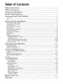
Table of Contents
Safety Instructions ...........................................................................................................................................2-3
Table of Contents .............................................................................................................................................4
Customer Information ............................................................................................................................s
Product
Spedfications ..............................................................................................................................s
Accessories and Tools Needed .........................................................................................................6
Accessories ....................................................................................................................................................................... .6
TOOLS ...................,...,.............................................________''''.._*_______'_.....'''________`____'_'''...''__._____'._.'''''''______________...'''______'_.._'_'6
Instructions for Installation ............................................................................................................7-2e
Removing the Old Water Heater ....................................................................................................................................... 7
Locating the New Water Heater ...................................................................................................................................... A_
Typical Installation ............................................................................................................................................................... 8
The Convertible Lower Element .................................................................................................................................... .9
Water Piping .................................................................................................................................................................... 10
Temperature-Pressure Relief Valve ................................................................................................................................... 11
Filling the Water Heater ................................................................................................................................................. 12
Converting the Lower Element ................................................................................................................................. 12-14
Wiring Diagram ............................................................................................................................................................. 15
Wiring ............................................................................................................................................................................... 16
Selecting Thermostat Location ........................................................................................................................................ 17
Routing Wire Harness to Location ................................................................................................................................ 17
Thermostat Removal ........................................................................................................................................... 17,18
Remote Thermostat Wiring at Water Heater .................................................................................................. 18-20
Remote Thermostat Installation and Wiring ......................................................................................................... 20,21
Installation Checklist .................................................................................................................................................. .22
Instructions for
Operation ..............................................................................................................23-26
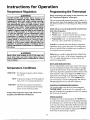
Temperature Regulatiom .................................................................................................................................................. .23
J.
Temperature Conditions ................................................................................................................................................. .,23
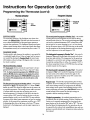
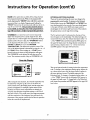
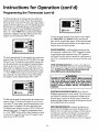
Programming the Thermostat ..................................................................................................................................... .23-26
Service and Maintenance ..................................................................................................................27-3a
Temperature-Pressure Relief Valve Operation .................................................................................................................... 27
Draining ............................................................................................................................................................................ 27
Element Cleaning and Replacement ......................................................................................................................... .28-30
Drain Valve Washer Replacement ...................................................................................................................................... 31
Service ............................................................................................................................................................................... 31
Tr_ub_pes_ha_t_[ng..::..2::::::::::::::::::::::::::::..:::::::::::::::::::::::::::::::::::::::.7:::::::::::::::::::::::::::::::::::::::::::::::7=========================::2._3_
Thermal Expansion ....................................................................................................................................................... .32
Strange Sounds. ............................................................................................................................................................ .32
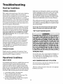
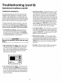
Operational Conditions ............................................................................................................................................. 32,33
Smelly Water .............................................................................................................................................................. .32
Air in Hot Water Faucets ............................................................................................................................................ .32
Rumbling Noise ............................................................................................................................................................ 32
High Temperature Shut OffSystem ...................................................................................................................... 32,33
Not Enough Hot Water ................................................................................................................................................ 33
Water is Too Hot ...................................................................................................................................................... .33
Thermostat Diagnostics ............................................................................................................................................... .34
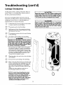
Leakage Checkpoints ................................................................................................................................................ 35
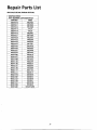
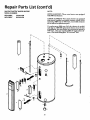
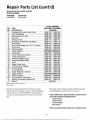
---RepairParts List ..........................................................................................................................................37-39
Warranty ...................................................................................................................................................................40
4

Customer Information
Thank You for purchasing a Maytag water heater. • The installation must conform with the instructions in this
Properly installed and maintained, it should give you years of manual; electric company rules; and Local Codes, or in the
trouble free service. It is strongly suggested that this new absence of Local Codes, with the latest edition of the
water heater be professionally installed, car Maytag Customer National Electrical Code. This publication is available from
Service at 1-800-788-8899 for recommended installers, your local government or public library or electric company
or by writing Underwriters Laboratories, 333 Pfingsten
Abbreviations Found In This Instruction Manual Road, Northbrook, IL 60062.
U.L.- Underwriters Laboratories, 333 Pfingsten Rd.,
Northbrook, IL 60062 • If after reading this manual you have any questions or do
National Electrical Code-This publication is available from not understand any portion of the instructions, call Maytag
Customer Service at 1-800-788-8899 for an authorized
your local government or pubfic library or electric company or servicer.
by writing to U.L above.
ANSI-American National Standards Institute
• CarefiAIy plan the place where you are going to put the
water heater. Correct electrical wiring and connections are
• Read the "Safety Instructions" section, pages 2 and 3 of this
very important in preventing death from possible electrical
manual, first and then the entire manual caxefi_ly. If you shock and fires.
don't follow the safety rules, the water heater will not oper-
Examine the location to ensure the water heater compiles
ate properly. It could cause DEATH, SERIOUS BODILY
INJURY AND/OR PROPERTY DAMAGE. with the "Locating the New Water Heater" section.
This manual contains instructions for the installation, oper-
ation, and maintenance of this electric water heater. It also • For California installation this water heater must be braced,
contains warnings throughout the manual that you must anchored, or strapped to avoid falling or moving during an
read and be aware of. All warnings and all instructions are earthquake. See instructions for correct installation proce-
essential to the proper operation of the water heater and dures. Instructions may be obtained from the California
office of the State Architect, 400 P Street, Sacramento, CA
your safety. Since we cannot put everything on the first few
95814.
pages, READ THIS ENTIRE MANUAL BEFORE
ATTEMPTING TO INSTALL OR OPERATE THE
WATER HEATER. Massachusetts Code requires this water heater to be
installed in accordance with Massachusetts 248-CMR 2.00:
State Plumbing Code and 248-CMR 5.00.
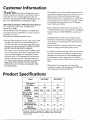
Product Specifications
Model HE21250PC HE21282PC
Tank Capacity
In Gallons 50 80
Element Upper 3800 3800
Wattage I I
at240Voh Lower 3800 ] 5500 3800 ] 5500
I I
Recovery Rate Upper 17.3 17.3
In Gals Per Hr.
I I
@90*FRise Lower 17.3 I 25 17.3 I 25
Diameter 22" 26.25"
Height 58.5" 62"
Maximum Fuse or
Circuit Breaker Size 20 30 20 30
Minimum
Wire Size (Gauge)* 12 10 12 10
*Wiring size based on standard 60°C copper wire. If distance from
fuse box to water heater is more than 90 feet, refer to your local
electrical code.
5

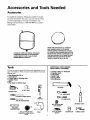
Accessoriesand ToolsNeeded
Accessories
To simpfify the installation Maytag has available the installa-
tion parts shown below. You may or may not need all of these
accessories depending on your type of installation. Call
Maytag Customer Service at 1-800-788-8899 for an autho-
rized installer.
DRAINPANSAVAILABLEIN 22" DIAMETER
(PARTNUMBER66001011) FORWATER
HEATERSHAVINGA DIAMETER20" OR LESS,
EXPANSIONTANKSFORTHERMALEXPANSION 24" DIAMETER(PARTNUMBER66001105) FOR
WATERHEATERSHAVINGA DIAMETER22" OR
CONDITIONSAVAILABLEIN 2 GALLON(PART LESSAND AVAILABLEIN 28"DIAMETER(PART
NUMBER66001013) AND SGALLON(PART NUMBER66001012) FORWATERHEATERS
NUMBER66001014) CAPACITY HAVINGA DIAMETER26.25" OR LESS
TOOLS ADDITIONAL TOOLS NEEDED
WHEN SWEAT SOLDERING
You may or may not need all of these tools, depending on your
type of installation. These tools can be purchased at your local * Tubing Cutters or Hacksaw
lVlaytag store. • Propane Torch
• Soft Solder
• Pipe Wrenches (2) 14"
• Screwdriver • Solder Flux
• Emery Cloth
• 6 Foot Tape of Folding Rule • Wire Brushes
• Garden Hose
• Drill
• Pipe dope or Teflon Tape
6 FOOTTAPE
GARDENHOSE
314_WIREBRUSH
SLOT-HEADSCREWDRIVER PIPE
- WRENCH 1/2" WIREBRUSH
PHILLIPSSCREWDRIVER _ _ PROPANETORCH
ROLLOFLEADFREE
PIPEDOPE _ SO. SOLDER(SQUEEZETUBE) _
ROLLOF TEFLONTAPE DRILL ROLLOF EMERY SOLDERFLUX TUBINGCUTTER
(Use only onwater connec- CLOTH
tions)
6

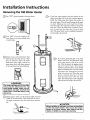
Installation Instructions
Removing the Old Water Heater
Turn "OFF" electrical supply to the water heater. @ a. If you have copper piping to the water heater, the two
copper water pipes can be cut with a hacksaw approxi-
_ mately four inches away from where they connect to
the water heater. This will avoid cutting off the pipes
too short. Additional cuts can be made later if neces-
sary. Disconnect the temperature-pressure relief valve
drain line. When the water heater is drained, discon-
nect the hose from the drain valve. Close the drain
valve. The water heater is now completely disconnect-
ed and ready to be removed.
@ T:::r "hOeF[]'orwater meter.:hlh:a::t_::PuPlY__C tff°vtab: Q_ _'li _ Q
Attach hose the heater drain
a
to water
valve and put the other end in a floor _1_ t1 @b. If you have galvanized pipe to the water
drain or outdoors. Open the water I_ ] heater, loosen the two galvanized pipes
heater drain valve. Open a nearby hot with a pipe wrench at the union in each
water faucet which will relieve pressure line. Also disconnect the piping remain-
in the water heater and speed draining, ing to the water heater. These pieces
should be saved since they may be needed
__ _ when reconnecting the new water heater.
Disconnect the temperature-pressure
relief valve drain line. When the water
heater is drained, disconnect the hose
from the drain valve. Close the drain
valve. The water heater is now completely
disconnected and
ready
to be removed.
_i WAR N IN G I-_-_-'1
The water passing out of the drain _ _
valve may be extremely hot. To
avoid being scalded, make sure all
connections are tight and that the
water flow is directed away from
any person.
Check again to make sure the electrical supply is turned
"OFF" to the water heater. Then disconnect the electri-
cal supply connection from the water heater junction
box.
Mineral buildup or _y have accumulated
in the old water heater. This causes the water /
__1_ heater to bemuch heavier than normal and this I
residue, if spilled out, could cause staining. ]
7

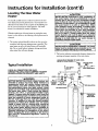
Instructions for Installation (cont'd)
Locating The New Water ACAUTION I
Heater WATER HEATERS EVENTUALLY LEAK: Installation of
the water heater must be accomplished in such a i
You should carefiany choose an indoor location for the new manner that if the tank or any connections should I
water heater, because the placement is a very important con- leak, the flow of water will not cause damage to the
structure. For this mason, it is not advisable to install I
sideration for the safety of the occupants in the building and the water heater in an attic or upper floor. When
for the most economical use of the appliance. This water such locations cannot be avoided, a suitable drain
heater is not intended for outdoor installation, pan should be installed under the water heater.
Drain pans are available at your local hardware
store. Such a drain pan must have a minimum diam-
Whether replacing an old water heater orpurring the water eter of at least 1'14inches greater than the water
heater in a new location, the following critical points must be heater diameter and must be piped to an adequate
drain. Under no circumstances tsthe manufacturer or
observed. Maytag to be held liable for any water damage in
connection with this water heater.
1. The location selected should be indoors as close to and as
centralized with the water piping system as possible. This _kCAUTION
water heater, as well as all water heaters, will eventually INSTALLATION IN RESIDENTIAL GARAGES: The water [
leak. Do not install without adequate drainage provisions heater must be located and/or protected so it is not [
where water flow will cause damage, subject to phys cal damage by a mov ng veh tie. [
2. The location selection must provide adequate clearances for
servicing and proper operation of the water heater.
VACUUMRELIEFREQUIREDBYSOMECODES
(REFERTOLOCALCODES)_ __
SHUTOFFVALVE
Typical Installation
CHECK ALL CONNECTIONS FOR LEAKS. _OUTL COLDWATERINLET
CONSULT THE LOCAL UTILITY COMPANY TO EXAM-
INE INSTALLATION FOR PROPRIETY AND SAFETY. ;=_ E_I ELBOW
HOTTER WATER CAN SCALD: Water heaters are
TEMPERED
intended to produce hot water. Water heated to a WATE_D
temperature which will satisfy clothes washing, OUTLET*MIXING VALVE ' L_--J_IE _-J JXPIPEINSULATION
dish washing, and other sanitizing needs can scald PIPE INSULATION / _'J_'_J
and permanently injure you upon contact. Some
people are more likely to be permanently injured by _ __
hot water than others. These include the elderly,
|
]1
children, the infirm, or physically/mentally handi-
capped. If anyone using hot water in your home fits ) _-.[-_TEMPERATURE-
into one of these groups or if there is a local code or PRESSURE
i RELIEFVALVE
state law requiring a certain temperature water at
the hot water tap, then you must take special pre-
cautions. In addition to using the lowest possible
temperature settingthat satisfies your hot water
needs, a means such as a mixing valve, should be
used at the hot water taps used by these people or I I .i --DISCHARGE PIPE
at the water heater. Mixing valves are available at _ plug)(D°notcapor
_alumbing supply or hardware stores. Follow manu-cturers instructions for installation of the valves.
Before changing the factory setting on the thermo- I
stat, read the "Temperature Regulation" section in
this manual.
8

Instructions for Installation (cont'd)
The Convertible Lower
Element
The Upper Element, is a conventional 3800 watt element
which only operates at its rated wattage on 240 volts.
(See rating plate on water heater).
The Lower Element of the water heater can be converted
from operation at 3800 watts to 5500 watts on a 240 volt
system.
Read and follow water heater warnings and instructions. If
after reading these instructions in this manual, if you do not
understand any portion, call Maytag Customer Service at
1-800-788-8899 for an authorized servicer.
AWARNING
Before making the conversion to 5500 watts, check
the (1) power supply...must be 240 volts, (2)
wiring...10 gauge AWG @ Type TW, 60oC or equiva-
lent, and (3) Circuit breakers or fusing...capable of
30 amp loading. Also, the installation must conform
with this manual, local codes and electric utility
rules. Failure to comply can result in DEATH, SERI-
OUS BODILY INJURY,OR PROPERTYDAMAGE.
NOTE: Whether or not the dement conversion is made the
model rating plate must be marked. Using ahard point ink
pen, check the appropriate block within the model rating
plate, which is located adjacent to the lower access panel.

Instructions for Installation (cont'd)
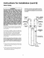
Water Piping
A WARNING NOTE: Your water heater is super insulated to minimize
HOTTER WATER CAN SCALD: Water heaters are heat lossfrom thetank. Further reductionin heatlosscan
intended to produce hot water. Water heated to a be accomplished by insulating the hot water lines fromthe
temperature which will satisfy clothes washing, water heater.
dish washing, and other sanitizing needs can scald
tnd permanently injure you upon contact. Some
_eople are more likely to be permanently injured by
lot water than others. These include the elderly,
children, the infirm, or physically/mentally handi-
capped. If anyone using hot water in your home fits
into one of these groups or if there is a local code or
state law requiring a certain temperature water at HOTOUTLETTO SHUT-OFF COLDINLET
the hot water tap, then you must take special pre- HOUSE VALVE (_) WATT_ERLINE
cautions. In addition to using the lowest possible '_ i1_1 _-_n
temperature settingthat satisfies your hot water _-_ _ % _ _-_ u----_ []_
i needs, a means such as a mixing valve, should be
usedotw--''h'--OrTHOOT:TH--TO
at the water heater. Mixing valves are available at SWEAT COUPLING I
plumbing supply or hardware stores. Follow manu-
I._1_ ATCOUPLING
facturers instructions for installation of the valves.
Before changing the factory setting on the thermo- INsuFI_ION U I I _ PIPEstat, read the "Temperature Regulation" section in U INSULATION
this manual.
3/4" THREADED---_--_/'_ _ 3/4"THREADED
The illustration shows the attachment of the water piping to NIPPLE _ NIPPLE
the water heater. The water heater is equipped with V. inch
water connections, i r ;
r
If a water heater is installed in a closed water supply system; [ J
.I
TEMPERATURE-
fPRESSURE RELIEF
( VALVE
such as one having a back-flow preventer, check valve, water b
meter with a check valve, etc. in the cold water supply;
means shall be provided to control thermal expansion.
Contact the local utility or call Maytag Customer Service at
1-800-788-8899 for an authorized servicer on how to con-
trol this situation. DISCHARGEPIPE
(Donotcaporplug)
NOTE: If using copper tubing, solder tubing to an adapter
before attaching the adaptor to the cold water inlet connec-
t/on. Do not solder the cold water supply line directly to the
cold water inlet. It will harm the dip tube and damage the
tank. L_
-7-
1. Look at the top cover of the water heater. The water outlet _ ( T 6"AIRGAP
is marked hot. Connect the hot water pipe to the hot water _ _ _'_
outlet of the water heater. "_ _
FLOORDRAIN
2. Look at the top cover of the water heater. The cold water
inlet is marked cold. Connect the cold water pipe to the
cold water inlet of the water heater.
10

Instructions for Installation (cont'd)
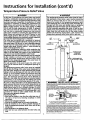
Temperature-Pressure Relief Valve
&WARNING J AWARNING
At the time of manufacturethis water heater was provid- 7he temperature-pressure relief valve must be manu-
eclwith a combination temperature-pressuresrelief va ve ally operated at least once a year. Caution should be
taken to ensure that (1) no one is in front of orcertified bya nationally recognizedtesting laboratory that
maintains periodic inspection of production of listed I around the outlet of the temperature-pressure relief
equipment or materials, as meeting the requirementsfor valve discharge line, and (2) the water manually dis-
ReliefValves and Automatic GasShutoff Devicesfor Hot !charged will not cause any bodily injury or property
Water Supply Systems, and the latest edition of ANSI damage because the water may be extremely hot.
ZZ1.22 and the code requirements of ASME. If replaced,
IIf after manually operating the valve, it fails to corn-
the valve mustmeet the requirementsof localcodes,but pletely reset and continues to release water, immedi-
not lessthan a combination temperature and pressure ately close the cold water inlet to the water heater,
relief valve certified as meeting the requirements for follow the draining instructions, and replace the
Relief Valvesand Automatic Gas Shutoff Devicesfor Hot ,temperature-pressure relief valve with a new one.
Water SupplySystems,ANSI Z21.22 by a nationally recog-
nized testing laboratorythat maintainsperiodicinspection _
of productionof listedequipmentor materials. H_OT CO<_LD
The valve must be marked with a maximum set pressure _-- _ _
not to exceedthe marked hydrostaticworkJngpressureof PIPE'-_-_ L _ L.t VALVE PIPE
the water heater (150 Ibs./sq.in.) and a dischargecapacity
not lessthan the water heater input rate as shownon the INSULATION _ _j_. _ _j_ INSULATION
model rating plate. (Electric heaters - watts divided by
1000x 3415 equal BTU/Hr.rate.)
Your localjurisdictional authority, while mandating the CONDUIT_ _ 3
useof a temperature-pressurerelief valve complyingwith ,' ' _ TEMPERATURE-
ANSIZ21.22 and ASME,may requirea valve model differ- _ PRESSURE
ent from the one furnishedwith the water heater. RELIEFVALVE
Compliancewith suchlocalrequirementsmust besatisfied
by the installer or end user of the water heater with a
locally prescribed temperature-pressure relief valve _ DISCHARGEPIPE
installedin the designatedopening in the water heater in _(Do notcapor plug)
placeof the factoryfurnishedvalve.
\
Forsafe operation of the water heater, the relief valve
must not be removed from it's designated opening or
pugged.
temperature-pressure relief valve must be installed
:ctly intothe fitting of the water heater designatedfor
reliefvalve. Positionthe valve downward and provide
tubing sothat any dischargewill exit only within 6 inches
above, or at any distance below the structural floor. Be ! _ j
certain that no contact is made with any live electrical
[
6"AIRGAP
part. The discharge opening must not be blocked or _ k,
E
treducedin size under any circumstances.Excessivelength, _ =_, ,; _ BF-
over 30 feet, or use of more than four etbows can cause FLOORDRAIN
r
restrictionand reducethe dischargecapacityofthe valve,
No valve or other obstructionisto be placedbetween the WARNING "RELIEF VALVE OPENING"
relief valveand the tank. Do not connecttubing directlyto Thdswaterheaterispf0_ded_thar_mbmatJonTernpeca_Jr_PressureReliefValve_stedascomplyingwi_
1hesianda_dforReliefWives_uTdAutomahcGasShutoffDevicesforHotWaterSupplySYstems,AJ_SZ21.22
discharge drain unlessa 6" air gap is provided.To prevent andlhecodete_JirementsofASME.
bodily injury,hazardto life, or propertydamage,the relief Yourlocaludsdic_lof,aia_, whilernardafi_lheuseofaTemoerature-PressureRel_fVal_complying
WI_ANSZ2 22andASME,mayrequ_'eavaJvemodedrlerentfromlheonelumshedv,_hthewaterheaer
valve must be allowed to discharge water in quantities C0mpliancewJlhsuc_lccalrequirementsmustbesa_s_edbylheinslal_r_endu_r_w=_h_ter_a locallypr¢scnbedTemperature-Pressute ReliefValveir_tailedinI_e des_gnateJopeninginthe water
shouldcircumstancesdemand, If the dischargepipe is not _r
connectedto a drain or other suitable means, the water
TANK _; l_ ,_ACK_
TANK '/ __' ' BRASS
FITFING COUPLING
VALVEPROBE TEMPERATURE
The DischargePipe:
MUST EXTEND PRESSURE
• Must not be smaller in size than the outlet pipe size of
IN3"OTANK _ _ RELtEFVAWE
the valve, or have any reducing couplings or other
BRASS
IPP ' SHANK
restrictions. _ _'_ _'_-_H
Must not be pluggedor blocked. • Ifashodshank(lessthan2")temperature=pressurereliefvalveistobeinstalled
I: Must be of material listed for hot water dislribution. _ _*_1,_,w_,__ _=_ ._Must be installed so as to allow complete drainage of • if a longshank(2" or longer}is to beinstalled,donotusethe nippleand coupling
both the temperature-pressurereliefvalve,andthedis- .=_, Temperature-PressureproteobveequipmentrequiredbyIocaJcodes,butnottessthana cc_nbma
t_onTemperature.PressureRelief VaJvecertified_s meetin the requirementsfor _elief Valves =lnd
charge pipe. Au_o_,_ GasShutoffDevicesfc_Hot-WaterSupplySysle_s,_S 721 22bya nafionaJlyrecognized_st-
I," M ust terminate at an adequate drain. _ lab°t_d°_ _hatr_a_l_tail_Pen°dieinspecb°r'of pr°dt¢_°_ Ollisteds_uipr°entOImaterialsThe valve
mustbe oriented,prowdedwilhtubing,c_ol_eaviseinstalledsothatdischargeca_exit0nlywilhin6 inches
Must not have any valve between the relief va ve and ._o_,,oratanydistar¢ebelow_ sbucturalfloor,andcannotcc_tactanyIweelecinc_rpad"
Forsafeoperat_nofIhewaterheater,IPeReliefValvemustnotberemovedor p_ugged.
tank. see manualheading =Temperature-PressureReliefValve' forinstallationand maintenanceof Relief
Valve,dischargepipeandolhelsafetyp_ecauhons

Instructions for Installation (cont'd)
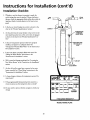
Filling the Water Heater
To £dl the water heater with water: [ AWARNING ]
1. Close the water heaterdrain valve by turning the handle to tiBefore making the conversion to 5500 watts, checkll
the right (clockwise). The drain valve is on the lower front I the (1) power supply...must be 240 volts, (2) /
of the water heater. I wiring...10 gauge AWG @ Type TW, 60"C or equiva-|
]lent, and (3) Circuit breakers or fusing...capable ofl
2. Open the cold water supply valve to the water heater. [ 30 amp loading. Also, the installation must conform |
NOTE: The coldwater supplyvalve must beleft open I with this ma nual, local codes and electric utility I
when the water heater is in use. ]rules. Failure to comply can result in DEATH, SERI-]
3. To insure complete fdling of the tank, allow air to exit by [ OUS BODILYINJURY, OR PROPERTY DAMAGE. ]
opening the nearest hot water faucet. Allow water to run
until a constant flow is obtained. This will let air out of the
water beater and the piping.
ACAUTION
Never use this water heater unless it is completely
full of water. To prevent damage to the tank and
heating element, the tank must be filled with
water. Water must flow from the hot water faucet
before turning "ON" power.
4. Check all new water piping for leaks. Repair as needed.
Converting the Lower
Element
These instructions only cover the conversion of the convert- NOTE: Whether or not the element conversion is made the
ible dement, read this entire manual before attempting to model rating plate must be marked. Using a hard point ink
install or operate the water heater. The water heater is factory pen, check the appropriate block vAthln the model rating
set to operate at 3800 watts. The lower element can be con- plate, which is located adjacent to the lower access panel.
vetted to operate at 5500 watts. Refer to "The Convertible
Lower Element" section. Necessary element conversion parts are located in a small bag
contained within the large plastic manual envelope attached
The Upper Element is a conventional 3800 watt element to the side of the water heater.
which only operates at its rated wattage on 240 volts. (See rat-
ing plate on water heater).
CONVERSIONPARTS
The Lower Element of the water heater can be converted
from operation at 3800 watts to 5500 watts on a 240 volt sys- /_
tern.
If after reading these instructions and this manual, if you do
not understand any portion, call Maytag Customer Service at
1-800-788-8899 for an authorized servicer. BUSSBAR
22

Instructions for Installation (cont'd)
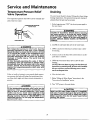
Converting the lower Element
(cont'd)
1. Before beginning the conversion turn "OFF" electric 4. Remove the screws from terfninal 2 of the element, and
power supply to the water heater, move the looped end of the wire aside.
@i,
WARNING 5. The buss bar is labeled 5500 W. Place the buss bar over ter-
minals 2 and 3 with the 5500 W visible. Install the extra
HAZARD OF ELECTRICAL SHOCK! Before removing
any access panels or servicing the water heater, screw provided into terminal 3.
make sure the electrical supply to the water heater
is turned "OFF". FAILURE TO DO THIS COULD
RESULT IN DEATH, SERIOUS BODILY iNJURY, OR
PROPERTYDAMAGE.
2. The convertible element is located behind the lower access
panel of the water heater. Remove the screw securing the
access panel, and remove panel.
6. The wire removed from terminal 2 has a looped end. It
must remain looped and now be placed (as shown) on top
of the buss bar, over the opening of terminal 2, and secured
_, using the remaining screw.
3. Remove the flap of insulation to expose the opening.
7. Tighten terminals 2 and 3 to ensure proper electrical con-
nection.
AWARNING l
Failure to tighten terminal screws can cause a fire]
which can result in DEATH, SERIOUS BODILY INJURY,[
OR PROPERTYDAMAGE.
/
13

Instructions for Installation (cont'd)
Converting the Lower Element
(cont'd)
8. Press the insulation back in place so that it completely cov- 10. Complete wiring to the water heater, or if completed, turn
ers the thermister and element. "ON" electric power to the water heater after filling the
tank with water.
ACAUTION ]
9. Replace the access panel. Never use this water heater unless it is completely /
full of water. To prevent damage to the tank andJ
__ heating element, the tank must be filled with water. |[
Water must flow from the hot water faucet before|
turning "ON" power.
_P
i4

Instructions for Installation (cont'd)
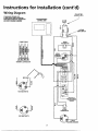
Wiring Diagram TOELECTRIC
POWER SUPPLY
STANDARD WIRING FOR
2 WIRE LEAD WATER HEATERS
NON-SIMULTANEOUS OPERATION PROGRAMMABLE
240 VOLT DOUBLE ELEMENT CONTROL UNIT AC 240
6_z
HI-TEMP
¢¢
,_ ,,n
i J
6-WIRE CABLE UPPER
THERMISTOR
z m 3
< =_ UPPER
O HEATING
ELEMENT
6 4321
I " ' """J
TERMINAL CONNECTOR
FOR 5500 WATTS
RELAYS &
BOARD
THERMISTOR
FOR 3800 WA'I-rS
LOWER
HEATING ELEMENT
15

Instructions for Installation (cont'd)
Wiring
•i_ CAUTION C. Flexible metal conduit or 3 metallic tubing shall be per-
Never use this water heater unless it is completely mitted for grounding if all the following conditions are
full of water. To prevent damage to the tank and met:
heating element, the tank must be filled with 1. The length in any ground return path does not exceed
water. Water must flow from the hot water faucet 6 feet.
before turning on power. 2. The circuit conductors contained therein are protected
by overcurrent devices rated at 20 amperes or less.
You must provide all wiring of the proper size outside of the 3. The conduit or tubing is terminated in fittings
water heater. You must obey local codes and electric company approved for grounding.
requirements when you install this wiring. For complete grounding details and all allowable exceptions,
refer to the latest edition of the National Electrical Code.
Ifyun are not familiar with electric codes and practices, or if
A s andar 1/,, -
you have any doubt, even the slightest doubt, in your ability to 4. t d ,_ conauit opening has been made in the water
connect the wiring to this water heater, obtain the service of a heater junction box for the conduit connection.
competent electrician. Call Maytag Customer Service at 5. A wiring diagram (See "Wiring Diagram" Section) has been
1-800-788-8899 for an authorized servicer, suppfied showing the connections between the water heater
and the power supply. You can easily see the connection by
WARNING removing the junction box cover on top of the water heater.
WATER HEATERS EQUIPPED FOR ONE VOLTAGE Connect red to red, black to black, and the ground wire to
the green ground screw in the junction box of the water
ONLY: This water heater is equipped for one type
voltage only. Check the rating plate near the bot- heater.
tom access panel for the correct voltage. DO NOT
use this water heater with any voltage other than 6. Use wire nuts and connect the power supplywiring to the
the one shown on the model rating plate. Failure to wires inside the water heater's junction box.
use the correct voltage can cause problems which
can result in DEATH, SERIOUS BODILY INJURY, OR 7. The water heater must be electrically "grounded" by the
PROPERTY DAMAGE. If you have any questions or
doubts consult your electric company, installer. A green ground screw has been provided on the
water heater's junction box. Connect ground wire to this
A CAUTION location.
If wiring from your fuse box or circuit breaker box 8. Replace the wiring junction cover using the screw provided,
was aluminum for your old water heater, replace it
with copper wire. If you wish to reuse the existing
aluminum wire, have the connection at the water
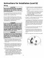
Mayta_ Customer Service at 1-800-788-8899 for an WIRE
authorized servicer. T
1. Provide away to easily shut off the electric power when CONDUIT _ /
working on the water beater. This could be with a circuit ,@GsGR_ _--
breaker or fuse block in the entrance box or a separate dis- /_
connect switch.
2. Install and connect a circuit directly from the main fuse or
circuit breaker box. This circuit must be the right size and
have its own fuse or circuit breaker. Refer to the chart in
the "Product Specifications" section for the correct size
wire and fuse or circuit breaker.
3. If metal conduit is used for the grounding conductor:
A. The grounding electrode conductor shall be of copper,
aluminum, or copperclad aluminum. The material shall
be of one continuous length without a splice orjoint.
B. Rigid metal conduit, intermediate metal conduit, or
electrical metallic tubing may be used for the grounding
means if conduit ortubing is terminated in fittings
approved for grounding. 16

Instructions for Installation (cont'd)
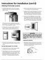
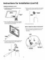
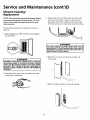
Selecting Thermostat Location
1. The programmable thermostat control module is shipped 6. Probe for any obstruction in the partition. In a clear area drill
attached to the front of the water heater, located behind the a %" hole through the wall at the selected location.
hinged cover panel.
7. Through this hole in the wall, drop a light chain or short chain
attached to a strong cord. Snag the cord with a hooked wire
from the basement. (In a home with no basement, drop the
cord from ceiling and snag it at the thermostat hole location.
8. Attach one end of the wiring harness to the cord. Pull the
cable through the hole in the wall so that 6 inches of cabh
protrudes. Other end of cable is to be routed back to the junc-
finn box on top of the water heater (Step 21). Before proceed-
ing, turn "OFF" the electric power supply to the water heater.
If this thermostat location is acceptable to the homeowner,
proceed directly to the "Installation Checklist" on page 22 and
then to "Temperature Regulation" on page 23.
2. The thermostat control module can alsobe installed next to
the home's heating or heating/coofing thermostat, or in
another convenient location remote from the water heater.
_WARNING
HAZARD OF ELECTRICAL SHOCK! Before removing I
any access panels or servicing the water heater, I
make sure,the electrical supply to the water heater I
is turned OFF . Failure to do this could result in
DEATH, SERIOUS BODILY INJURY, OR PROPERTY
DAMAGE.
THERMOSTATREMOVAL
3. The remote location should be about 5 feet above the floor 9. Holding fingers along the top and thumb on bottom, between
on any wall with good air circulation at average room tern- the thermostat and wall plate, gently remove thermostat from
perature, the wall plate. The thermostat will be installed at the selected
remote location in Steps 32 and 33.
ROUTINGWIREHARNESSTOLOCATION
4. A wiring harness kit for up to 50 feet of wiring is available j.._'_,
(see Repair Parts list) from your Maytag Dealer. ___
5. Before drilling ahole in the wall at the selected location, take _'_
up floor moulding (quarter round or other) and drill a small
guide hole for sighting. From the basement, drill a V/' hole in
partition floor next to guide hole (in homes with no base-
ment, drill a V/' hole through ceiling abovethe partition),
17

Instructions for Installation (cont'd)
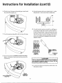
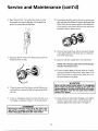
THERMOSTAT REMOVAL (cont'd)
10.C_tte_u_y discozln_ witiRg harfleasternlJflltlconnector 13.Presstheend ofthe thermostatcablebackintothe insulating
frombackofthermostat, bushing.No other connectionswillbe madeto thisend of
__RAMBOLES the cable.
_, BACKOF INSULATING
THERMO_$_T. _ RUSHING
TAT WIRING
HARNESS
TERMINAL
CONNECTOR
11.Removethewallplatefromthewater heaterbyunscrewing
the two mountingscrews.Thewall platewii1beinstalledat
the selected location in Steps 28 and 29. 14. Close and latch outer door.
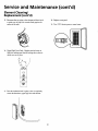
REMOTETHERMOSTATWIRINGATWATERHEATER
15.Removemountingscrewandrightjunctionboxcover.Also
liftup andremoveblackplugon leftjunctionboxcover,
Discardplug.
BLACK
MOUNTING_7SCREWS _ GIPLUG
12.Looseneachscrewin the terminalconnectorandremovethe /] ,i
wireends.The terminal connectorwillbe installedatthe
2
selected remote location in Step 31.
W.R.NG R,.HT'
.AR.E_S BOXCOVER\
BOX COVER
SCREW _ o
SLOTS- TERMINAL
CONNECTOR
c<
18

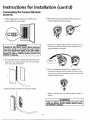
Instructions for Installation (cont'd)
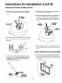
16. Find the loop of thermostat wiring cable (grey colored) inside 19. Strip the thermostat cable outer insulation back I_A inches.
the junction box and pull it out. Strip the ends % inch on each of the sixcolored wires.
LOOP _ m ud
__ J_ O _ ._ 1.250"
20. A second terminal connector is provided in a small bag con-
tained within the large plastic manual envelope attached to
the side of the water heater. Loosen each screw in the termi-
nal connector. Insert the sixcolored wires of the thermostat
17. Cut the thermostat wiring cable in half at the top of the loop. cable into the terminal connector and tighten each screw to
secure each wire. Be sure to arrange wires in exact color
sequence asshowm
6-WIRECA"LE
Lu _ =
z _ =
TERMINAL
6 A 2 1 _TCONNECTOR
TERMtNAL ( _ THERMOSTAT
CONNECTOR _E
18. The wire side of the loop which does not have the red tape
strip on it should be cut off or pressed into the junction box
out of the way. A CAUTION
The six colored insulated wires must be installed in
the terminal connector exactly as shown for the
thermostat to operate correctly.
I TH_AT 21. Locate the end of the remote thermostat cable routed to the
water heater in Step 8.
R_RTIApPE
ACTIc_ ALF
19

Instructions for Installation (cont'd)
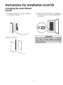
SelectingThermostatLocation(cont'd)
22. Guide the end of the remote thermostat cable through the 25. Carefully press the terminal connector and connected wires
hole where the black plug was removed in the left junction down into the water heater junction box.
box cover.
26. A strain-relief bushing is also provided in the small bag that
X REMOTE contained the terminal connector. Open the bushing and
HERMOSTAT place it around the remote thermostat cable exiting the junc-
CABLE
tion box. Press the bushing into the hole in the left junction
box cover,
INSULATING
REMOTE STRAIN-RELIEF
THERMOSTAT BUSHING
TERMINAL
CONNECTOR
23. Strip the end of the remote thermostat cable outer insulation
back 11/4inches. Strip the ends 1/4inch on each of the six col-
ored wires.
m ua _.250"
b- t- u_
"_ _ _" _ 27. Replace the right junction box cover using the screw provid-
_t it !_ !t !t _t_SO" heater,ed'This completes the remote thermostat wiring at the water
28. Locate the 6 inches of remote thermostat cable protruding
24. Loosen each screw in the terminal connector one at a time through the wall opening (from Step 8). Using the wall plate
and insert wire with the same color insulatlon into each removed in Step 11, pull the cable through opening near cen-
nmnbered slot. Tighten each screw securely making sure ter of wall plate.
both wires in each slot are tight.
TERMINAL
REMOTE _ff CONNECTOR
THERMOSTAT /_Y_vt-J- THERMOSTAT \ _TH'ER'MOSI"AT -_
CABLEfJ--/ CABLEFROM CABLE
_/ _ WATER HEATER
r _ _ j
20
Page is loading ...
Page is loading ...
Page is loading ...
Page is loading ...
Page is loading ...
Page is loading ...
Page is loading ...
Page is loading ...
Page is loading ...
Page is loading ...
Page is loading ...
Page is loading ...
Page is loading ...
Page is loading ...
Page is loading ...
Page is loading ...
Page is loading ...
Page is loading ...
Page is loading ...
Page is loading ...
-
 1
1
-
 2
2
-
 3
3
-
 4
4
-
 5
5
-
 6
6
-
 7
7
-
 8
8
-
 9
9
-
 10
10
-
 11
11
-
 12
12
-
 13
13
-
 14
14
-
 15
15
-
 16
16
-
 17
17
-
 18
18
-
 19
19
-
 20
20
-
 21
21
-
 22
22
-
 23
23
-
 24
24
-
 25
25
-
 26
26
-
 27
27
-
 28
28
-
 29
29
-
 30
30
-
 31
31
-
 32
32
-
 33
33
-
 34
34
-
 35
35
-
 36
36
-
 37
37
-
 38
38
-
 39
39
-
 40
40


Maytag HE21250PC User manual
- Category
- Water heaters & boilers
- Type
- User manual
- This manual is also suitable for
Ask a question and I''ll find the answer in the document
Finding information in a document is now easier with AI
Related papers
-
Maytag HE31282T User manual
-
-
Intertherm H3HK Large Package Electric Heater Kit (includes Wiring Diagrams) Product information
-
-
-
-
-
-
Maytag HP41250X User manual
-
Other documents
-
State Water Heaters ES6-20-SOMS-K User manual
-
State Water Heaters P6-30-2OT1 User manual
-
Kenmore 153.318031 User manual
-
-
Sears 53.329563 POWER MISER 9 153.329662 User manual
-
-
-
-
-