Page is loading ...

THIS MANUAL MUST ACCOMPANY THE EQUIPMENT AT ALL TIMES.
To find the latest revision of this
publication, visit our website at:
www.mqpower.com
®
MODEL SG1400C3
3-POSITION SWITCH/PARALLELING
1400 AMP STUDIO GENERATOR
(CUMMINS QSB7-G5 DIESEL ENGINE)
Revision #0 (10/05/11)
OPERATION MANUAL
EE55916

PAGE 2 — SG1400C3 STUDIO GENERATOR • OPERATION MANUAL — REV. #0 (10/05/11)
PROPOSITION 65 WARNING
Diesel engine exhaust and some of

SG1400C3 STUDIO GENERATOR • OPERATION MANUAL — REV. #0 (10/05/11) — PAGE 3
If you believe that your vehicle has a defect that could cause a crash or could cause
injury or death, you should immediately inform the National Highway Traffic Safety
Administration (NHTSA) in addition to notifying Multiquip at 1-800-421-1244.
If NHTSA receives similar complaints, it may open an investigation, and if it finds
that a safety defect exists in a group of vehicles, it may order a recall and remedy
campaign. However, NHTSA cannot become involved in individual problems
between you, your dealer, or Multiquip.
To contact NHTSA, you may either call the Vehicle Safety Hotline toll-free at 1-888-
327-4236 (TTY: 1-800-424-9153), go to http://www.nhtsa.dot.gov; or write to:
Administrator
NHTSA
1200 New Jersey Avenue S.E.
Washington, DC 20590
You can also obtain information about motor vehicle safety from
http://www.safecar.gov.
REPORTING SAFETY DEFECTS

PAGE 4 — SG1400C3 STUDIO GENERATOR • OPERATION MANUAL — REV. #0 (10/05/11)
TABLE OF CONTENTS
SG1400C3
Studio Generator
Proposition 65 Warning ........................................... 2
Reporting Safety Defects ......................................... 3
Table Of Contents .................................................... 4
Parts Ordering Procedures ...................................... 5
Safety Information .............................................. 6-11
Specifications ........................................................ 12
Dimensions ............................................................ 13
Installation ........................................................ 14-15
General Information .......................................... 16-18
Generator Major Components .......................... 20-21
Basic Engine Components ............................... 22-23
Control Panel ......................................................... 24
Camlok/Voltage Output Panel ................................ 25
Circuit Breaker Panel ............................................. 26
Digital Controller ................................................... 27
Load Application/Generator Output ....................... 28
Generator Outputs ................................................. 29
Inspection/Setup ............................................... 30-33
Startup .............................................................. 34-35
Protective Devices ................................................. 36
Maintenance ..................................................... 37-42
Troubleshooting (Generator) .................................. 43
Troubleshooting (Engine) ....................................... 44
Troubleshooting (Controller) .................................. 45
Trailer Guidelines ............................................. 46--60
NOTICE
Specifications are subject to change without notice.

SG1400C3 STUDIO GENERATOR • OPERATION MANUAL — REV. #0 (10/05/11) — PAGE 5
www.multiquip.com
Ordering parts has never been easier!
Choose from three easy options:
WE ACCEPT ALL MAJOR CREDIT CARDS!
When ordering parts, please supply:
❒ Dealer Account Number
❒ Dealer Name and Address
❒ Shipping Address (if different than billing address)
❒ Return Fax Number
❒ Applicable Model Number
❒ Quantity, Part Number and Description of Each Part
❒ Specify Preferred Method of Shipment:
✓ UPS/Fed Ex ✓ DHL
■ Priority One ✓ Truck
■ Ground
■ Next Day
■ Second/Third Day
If you have an MQ Account, to obtain a Username
and Password, E-mail us at: parts@multiquip.
com.
To obtain an MQ Account, contact your
District Sales Manager for more information.
Order via Internet (Dealers Only):
Order parts on-line using Multiquip’s SmartEquip website!
■ View Parts Diagrams
■ Order Parts
■ Print Specification Information
Note: Discounts Are Subject To Change
Goto www.multiquip.com and click on
Order Parts
to log in and save!
Use the internet and qualify for a 5% Discount
on Standard orders for all orders which include
complete part numbers.*
Order via Fax (Dealers Only):
All customers are welcome to order parts via Fax.
Domestic (US) Customers dial:
1-800-6-PARTS-7 (800-672-7877)
Fax your order in and qualify for a 2% Discount
on Standard orders for all orders which include
complete part numbers.*
Order via Phone:
Domestic (US) Dealers Call:
1-800-427-1244
Best Deal!
International Customers should contact
their local Multiquip Representatives for
Parts Ordering information.
Non-Dealer Customers:
Contact your local Multiquip Dealer for
parts or call 800-427-1244 for help in
locating a dealer near you.
Note: Discounts Are Subject To Change
Effective:
January 1
st
, 2006
NOTICE
All orders are treated as Standard Orders and will
ship the same day if received prior to 3PM PST.
PARTS ORDERING PROCEDURES

PAGE 6 — SG1400C3 STUDIO GENERATOR • OPERATION MANUAL — REV. #0 (10/05/11)
SAFETY INFORMATION
Do not operate or service the equipment before reading the
entire manual. Safety precautions should be followed at all
times when operating this equipment. Failure to read and
understand the safety messages and operating instructions
could result in injury to yourself and others.
SAFETY MESSAGES
The four safety messages shown below will inform you
about potential hazards that could injure you or others. The
safety messages specifi cally address the level of exposure
to the operator and are preceded by one of four words:
DANGER, WARNING, CAUTION or NOTICE.
SAFETY SYMBOLS
DANGER
Indicates a hazardous situation which, if not avoided,
WILL result in DEATH or SERIOUS INJURY.
WARNING
Indicates a hazardous situation which, if not avoided,
COULD result in DEATH or SERIOUS INJURY.
CAUTION
Indicates a hazardous situation which, if not avoided,
COULD result in MINOR or MODERATE INJURY.
NOTICE
Addresses practices not related to personal injury.
Potential hazards associated with the operation of this
equipment will be referenced with hazard symbols which
may appear throughout this manual in conjunction with
safety messages.

SG1400C3 STUDIO GENERATOR • OPERATION MANUAL — REV. #0 (10/05/11) — PAGE 7
SAFETY INFORMATION
GENERAL SAFETY
CAUTION
NEVER operate this equipment without proper protective
clothing, shatterproof glasses, respiratory protection,
hearing protection, steel-toed boots and other protective
devices required by the job or city and state regulations.
NEVER operate this equipment when not
feeling well due to fatigue, illness or when
under medication.
NEVER operate this equipment under the infl uence of
drugs or alcohol.
ALWAYS check the equipment for loosened threads or
bolts before starting.
DO NOT use the equipment for any purpose other than
its intended purposes or applications.
NOTICE
This equipment should only be operated by trained and
qualifi ed personnel 18 years of age and older.
Whenever necessary, replace nameplate, operation and
safety decals when they become diffi cult read.
Manufacturer does not assume responsibility for any
accident due to equipment modifi cations. Unauthorized
equipment modifi cation will void all warranties.
NEVER use accessories or attachments that are not
recommended by MQ Power for this equipment. Damage
to the equipment and/or injury to user may result.
ALWAYS know the location of the nearest
fi re extinguisher.
ALWAYS know the location of the nearest
fi rst aid kit.
ALWAYS know the location of the nearest
phone or keep a phone on the job site.
Also, know the
phone numbers of the nearest ambulance, doctor
and
fi re department.
This information will be invaluable in
the case of an emergency.
GENERATOR SAFETY
DANGER
NEVER operate the equipment in an explosive
atmosphere or near combustible materials. An
explosion or fi re could result causing severe
bodily harm or even death.
WARNING
NEVER disconnect any
emergency or safety devices.
These devices are intended for operator safety.
Disconnection of these devices can cause severe injury,
bodily harm or even death. Disconnection of any of these
devices will void all warranties.
CAUTION
NEVER lubricate components or attempt service on a
running machine.
NOTICE
ALWAYS
ensure generator is on level ground before use.
ALWAYS
keep the machine in proper running condition.
Fix damage to machine and replace any broken parts
immediately.
ALWAYS
store equipment properly when it is not being
used. Equipment should be stored in a clean, dry location
out of the reach of children and unauthorized personnel

PAGE 8 — SG1400C3 STUDIO GENERATOR • OPERATION MANUAL — REV. #0 (10/05/11)
SAFETY INFORMATION
ENGINE SAFETY
DANGER
The engine fuel exhaust gases contain poisonous carbon
monoxide. This gas is colorless and odorless, and can
cause death if inhaled.
The engine of this equipment
requires an adequate free
fl ow of cooling air. NEVER
operate this equipment in
any enclosed or narrow area
where free fl ow of the air is
restricted. If the air fl ow is
restricted it will cause injury to people and property and
serious damage to the equipment or engine.
WARNING
DO NOT place hands or fingers inside engine
compartment when engine is running.
NEVER operate the engine with heat shields or
guards removed.
Keep fi ngers, hands hair and clothing away
from all moving parts to prevent injury.
DO NOT remove the radiator cap while the
engine is hot. High pressure boiling water
will gush out of the radiator and severely
scald any persons in the general area of
the generator.
DO NOT remove the coolant drain plug while the engine
is hot. Hot coolant will gush out of the coolant tank and
severely scald any persons in the general area of the
generator.
DO NOT remove the engine oil drain plug while the
engine is hot. Hot oil will gush out of the oil tank and
severely scald any persons in the general area of the
generator.
CAUTION
NEVER touch the hot exhaust manifold,
muffl er or cylinder. Allow these parts to cool
before servicing equipment.
NOTICE
NEVER
run engine without an air fi lter or with a dirty air
fi lter. Severe engine damage may occur. Service air fi lter
frequently to prevent engine malfunction.
NEVER tamper with the factory settings
of the engine or engine governor. Damage
to the engine or equipment can result
if operating in speed ranges above the
maximum allowable.
Wet stacking is a common problem with diesel engines
which are operated for extended periods with light or
no load applied. When a diesel engine operates without
suffi cient load (less than 40% of the rated output), it will
not operate at its optimum temperature. This will allow
unburned fuel to accumulate in the exhaust system,
which can foul the fuel injectors, engine valves and
exhaust system, including turbochargers, and reduce
the operating performance.
In order for a diesel engine to operate at peak effi ciency,
it must be able to provide fuel and air in the proper ratio
and at a high enough engine temperature for the engine
to completely burn all of the fuel.
Wet stacking does not usually cause any permanent
damage and can be alleviated if additional load is
applied to relieve the condition. It can reduce the system
performance and increase maintenance. Applying an
increasing load over a period of time until the excess
fuel is burned off and the system capacity is reached
usually can repair the condition. This can take several
hours to burn off the accumulated unburned fuel.
State Health Safety Codes and Public Resources
Codes specify that in certain locations, spark arresters
must be used on internal combustion engines that use
hydrocarbon fuels. A spark arrester is a device designed
to prevent accidental discharge of sparks or fl ames
from the engine exhaust. Spark arresters are qualifi ed
and rated by the United States Forest Service for this
purpose. In order to comply with local laws regarding
spark arresters, consult the engine distributor or the
local Health and Safety Administrator.

SG1400C3 STUDIO GENERATOR • OPERATION MANUAL — REV. #0 (10/05/11) — PAGE 9
SAFETY INFORMATION
FUEL SAFETY
DANGER
DO NOT start the engine near spilled fuel or combustible
fl uids. Diesel fuel is extremely fl ammable and its vapors
can cause an explosion if ignited.
ALWAYS refuel in a well-ventilated area, away from
sparks and open fl ames.
ALWAYS use extreme caution when working with
fl ammable liquids.
DO NOT fi ll the fuel tank while the engine is running
or hot.
DO NOT overfi ll tank, since spilled fuel could ignite if it
comes into contact with hot engine parts or sparks from
the ignition system.
Store fuel in appropriate containers, in well-ventilated
areas and away from sparks and fl ames.
NEVER use fuel as a cleaning agent.
DO NOT smoke around or near the
equipment. Fire or explosion could result
from fuel vapors or if fuel is spilled on a
hot engine.
TOWING SAFETY
CAUTION
Check with your local county or state safety
towing regulations, in addition to meeting
Department of Transportation (DOT)
Safety Towing Regulations, before towing
your generator.
Refer to MQ Power trailer manual for additional safety
information.
In order to reduce the possibility of an accident while
transporting the generator on public roads, ALWAYS
make sure the trailer that supports the generator and
the towing vehicle are mechanically sound and in good
operating condition.
ALWAYS shutdown engine before transporting
Make sure the hitch and coupling of the towing vehicle
are rated equal to, or greater than the trailer “gross
vehicle weight rating.”
ALWAYS inspect the hitch and coupling for wear.
NEVER
tow a trailer with defective hitches, couplings, chains, etc.
Check the tire air pressure on both towing vehicle and
trailer.
Trailer tires should be infl ated to 50 psi cold.
Also check the tire tread wear on both vehicles.
ALWAYS make sure the trailer is equipped with a
safety
chain.
ALWAYS properly
attach trailer’s safety chains to towing
vehicle.
ALWAYS
make sure the vehicle and trailer directional,
backup, brake and trailer lights are connected and
working properly.
DOT Requirements include the following:
• Connect and test electric brake operation.
• Secure portable power cables in cable tray with tie
wraps.
The maximum speed for highway towing is 55 MPH
unless
posted otherwise. Recommended off-road towing is not to
exceed 15 MPH or less depending on type of terrain.
Avoid sudden stops and starts. This can cause skidding,
or jack-knifi ng. Smooth, gradual starts and stops will
improve towing.
Avoid sharp turns to prevent rolling.
Trailer should be adjusted to a level position at all times
when towing.
Raise and lock trailer wheel stand in up position when
towing.
Place chock blocks underneath wheel to prevent
rolling
while parked.
Place support blocks
underneath the trailer’s bumper
to prevent tipping while parked.
Use the trailer’s swivel jack to adjust the trailer height to
a level position while parked.

PAGE 10 — SG1400C3 STUDIO GENERATOR • OPERATION MANUAL — REV. #0 (10/05/11)
SAFETY INFORMATION
ELECTRICAL SAFETY
DANGER
DO NOT touch output terminals during
operation. Contact with output terminals
during operation can cause electrocution,
electrical shock or burn.
The electrical voltage required to
operate the generator can cause severe
injury or even death through physical contact with live
circuits. Turn generator and all circuit breakers OFF
before performing maintenance on the generator or
making contact with output terminals.
NEVER insert any objects into the output
receptacles during operation. This is
extremely dangerous. The possibility exists
of electrical shock, electrocution or
death.
Backfeed to a utility system can cause
electrocution and/or property damage.
NEVER connect the generator to a
building’s electrical system without
a transfer switch or other approved
device. All installations should be
performed by a licensed electrician in accordance with
all applicable laws and electrical codes. Failure to do so
could result in electrical shock or burn, causing serious
injury or even death.
Power Cord/Cable Safety
DANGER
NEVER let power cords or cables lay in water.
NEVER stand in water while AC power from the
generator is being transferred to a load.
NEVER use damaged or worn cables or cords when
connecting equipment to generator. Inspect for cuts in
the insulation.
NEVER grab or touch a live power
cord or cable with wet hands. The
possibility exists of electrical shock,
electrocution or death.
Make sure power cables are securely connected to the
generator’s output receptacles. Incorrect connections
may cause electrical shock and damage to the
generator.
NOTICE
ALWAYS
make certain that proper power or extension
cord has been selected for the job. See Cable Selection
Chart in this manual.
Grounding Safety
DANGER
ALWAYS
make sure that electrical circuits are properly
grounded to a suitable earth ground (ground rod) per
the National Electrical Code (NEC) and local codes
before operating generator.
Severe injury or death by
electrocution
can result from operating an ungrounded
generator.
NEVER use gas piping as an electrical ground.

SG1400C3 STUDIO GENERATOR • OPERATION MANUAL — REV. #0 (10/05/11) — PAGE 11
SAFETY INFORMATION
BATTERY SAFETY
DANGER
DO NOT drop the battery. There is a possibility that the
battery will explode.
DO NOT expose the battery to open fl ames,
sparks, cigarettes, etc. The battery contains
combustible gases and liquids. If these
gases and liquids come into contact with a
fl ame or spark, an explosion could occur.
WARNING
ALWAYS wear safety glasses when handling
the battery to avoid eye irritation. The battery
contains acids that can cause injury to the
eyes and skin.
Use well-insulated gloves when picking up the battery.
ALWAYS keep the battery charged. If the battery is not
charged, combustible gas will build up.
ALWAYS recharge the battery in a well-ventilated
environment to avoid the risk of a dangerous concentration
of combustible gasses.
If the battery liquid (dilute sulfuric acid) comes into
contact with clothing or skin, rinse skin or clothing
immediately with plenty of water.
If the battery liquid (dilute sulfuric acid) comes into
contact with eyes, rinse eyes immediately with plenty
of water and contact the nearest doctor or hospital to
seek medical attention.
CAUTION
ALWAYS disconnect the NEGATIVE battery terminal
before performing service on the generator.
ALWAYS keep battery cables in good working condition.
Repair or replace all worn cables.
ENVIRONMENTAL SAFETY
NOTICE
Dispose of hazardous waste properly.
Examples of potentially hazardous waste
are used motor oil, fuel and fuel fi lters.
DO NOT use food or plastic containers to
dispose of hazardous waste.
DO NOT
pour waste, oil or fuel directly onto the ground,
down a drain or into any water source.

PAGE 12 — SG1400C3 STUDIO GENERATOR • OPERATION MANUAL — REV. #0 (10/05/11)
SPECIFICATIONS
Table 1. Generator Specifications
Model
SG1400C3
Type
Revolving field, self ventilated,
open protected type synchronous generator
Armature Connection
12-Lead WYE
No of Poles
4
Prime Output
200 kVA
1Ø Voltage
120/240 V
3Ø Voltages
120/208 V and 277/480 V
Frequency
60 Hz
Voltage Regulation
(no load to full load)
±1%
Frequency Regulation
(steady state load)
±0.25%
Speed
1800 rpm
Power Factor
0.8
Aux. AC Voltage
120/240V, 60 Hz
Weight (Generator Only)
5,900 lbs. (2,994 kg)
Weight (Trailer Only)
2,640 lbs. (1,170 kg)
Dimensions (LxWxH)
100 x 48 x 110 in (254 x 122 x 279 cm)
Table 2. Engine Specifications
Model
Cummins QSB7-G5
Emissions
Tier 3
Type
4 cycle, direct injection, turbocharged,
charge air cooled
No. of Cylinders
6 cylinders
Bore x Stroke in (mm)
4.21 x 4.88 (107 x 124)
Displacement
408 cu. in. (6,690 cc)
Rated Output
279 HP/1800 RPM
Starting
Electric
Coolant Capacity
7.8 gal. (29 liters)
Lube Oil Capacity
5.0 gal. (19.0 liters)
Fuel Type
#2 Diesel Fuel
Fuel Tank Capacity
150 gal. (567 liters)
Fuel Consumption
13.3 gal. (64 L)/hr at full load 10.6 gal. (40 L)/hr at 3/4 load
7.8 gal. (30 L)/hr at 1/2 load 4.0 gal. (15 L)/hr at 1/4 load
Table 3. Battery Specifications
Battery (Top Post)
12V 750 CCA x 2 (24 VDC System ) Group 27
Dimensions HxWxL in. (cm)
8 x 12 x 6.6 (20.3 x 30.5 x 16.8)

SG1400C3 STUDIO GENERATOR • OPERATION MANUAL — REV. #0 (10/05/11) — PAGE 13
DIMENSIONS
E
F
H
G
I
D
J
TOP VIEW
A
B
FRONT VIEW
K
L
SIDE VIEW
AC VOLTS
AC AMPERES
AC AMPERES
M
AC AMPERES HERTZ
C
Table 4. Dimensions
Reference
Letter
Dimensions
in. (mm)
Reference
Letter
Dimensions
in. (mm)
A 90 (2,286) H 130 (3,302)
B 115 (2,921) I 22.5 (571)
C 96 (2,438) J
23 (584)
Chrome Wheels
D 27 (686)
J
24 (610)
Aluminum Wheels
E 24 (610)
K
180 (4,572)
F 24 (610)
L
24.5 (622)
G 79 (2,007) M 47 (1,194)
Figure 1. Dimensions

PAGE 14 — SG1400C3 STUDIO GENERATOR • OPERATION MANUAL — REV. #0 (10/05/11)
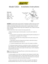
INSTALLATION
GROUND ROD
FOR EARTH
GROUND
GROUND CABLE
GENERATOR
GROUND LUG
CONNECT TO
BUILDING
GROUND
8 FT. MINIMUM
REFERENCE
NEC 250-52(C)
NOTE: GROUND LUG MUST
BE INSTALLED BY USER.
Figure 2. Typical Generator Grounding Application

SG1400C3 STUDIO GENERATOR • OPERATION MANUAL — REV. #0 (10/05/11) — PAGE 15
INSTALLATION
OUTDOOR INSTALLATION
Install the generator in a area that is free of debris,
bystanders, and overhead obstructions. Make sure the
generator is on secure level ground so that it cannot slide
or shift around. Also install the generator in a manner so
that the exhaust will not be discharged in the direction of
nearby homes.
The installation site must be relatively free from moisture
and dust. All electrical equipment should be protected from
excessive moisture. Failure to do will result in deterioration
of the insulation and will result in short circuits and
grounding.
Foreign materials such as dust, sand, lint and abrasive
materials have a tendency to cause excessive wear to
engine and alternator parts.
INDOOR INSTALLATION
Exhaust gases from diesel engines are extremely
poisonous. Whenever an engine is installed indoors the
exhaust fumes must be vented to the outside. The engine
should be installed at least two feet from any outside wall.
Using an exhaust pipe which is too long or too small can
cause excessive back pressure which will cause the engine
to heat excessively and possibly burn the valves.
CAUTION
Pay close attention to ventilation when operating the
generator inside tunnels and caves. The engine exhaust
contains noxious elements. Engine exhaust must be
routed to a ventilated area.
GENERATOR GROUNDING
To guard against electrical shock and possible damage to
the equipment, it is important to provide a good EARTH
ground.
Article 250 (Grounding) of the National Electrical Code
(NEC) provides guidelines for proper grounding and
specifies that the cable ground shall be connected to the
grounding system of the building as close to the point of
cable entry as practical.
NEC articles 250-64(b) and 250-66 set the following
grounding requirements:
1. Use one of the following wire types to connect the
generator to earth ground.
a. Copper - 10 AWG (5.3 mm
2
)
b. Aluminum - 8 AWG (8.4 mm
2
)
2. When grounding the generator (Figure 2) connect the
ground cable between the lock washer and the nut on
the generator and tighten the nut fully. Connect the
other end of the ground cable to earth ground.
3. NEC article 250-52(c) specifies that the earth ground rod
should be buried a minimum of 8 ft. into the ground.
NOTICE
When connecting the generator to any buildings
electrical system ALWAYS consult with a licensed
electrician.
NOTICE
If connection of the ground rod is not feasible, please
check city, local or state electrical requirements on
generator grounding requirements.

PAGE 16 — SG1400C3 STUDIO GENERATOR • OPERATION MANUAL — REV. #0 (10/05/11)
GENERAL INFORMATION
Generator
The MQ Power Model SG1400C3 is a 200kVA studio
generator that is designed as a high quality power source
for entertainment and studio applications.
In keeping with Multiquip's policy of constantly improving
its products, the specifications quoted herein are subject
to change without prior notice.
Permanent Magnet Generator Excitation System
The SG1400C3 generator is equipped with a PMG
(Permanent Magnet Generator) generator end. The
excitation system provides a minimum short circuit support
current of 300% of the standby rating for 10 seconds at 60
Hz, and approximately 275% at 50 Hz.
Both the PMG and the exciter are mounted outboard of the
bearing for ease of maintenance. The rotating brushless
exciter features hermetically sealed diodes for three-phase
full-wave rectification. The three-phase bridge is protected
against abnormal transient conditions by a multiplate
selenium surge protector.
Engine
This generator is powered by a six-cylinder, 4-cycle direct
injection, turbocharged, air-cooled Cummins QSB7-G5
diesel engine. Engine speed is set at the factory at 1800
RPM. This engine is designed to meet every performance
requirement for the generator. Refer to Table 2 for engine
specifications.
Principle Of Operation
This generator is a brushless, self-excited, externally
voltage regulated, synchronous AC generator. The
generator is made up of six major components: main stator
(armature), main rotor (field), exciter stator (field), exciter
rotor (armature), rectifier assembly, and voltage regulator.
The generator's exciter consists of a stationary field and
a rotating armature. The stationary field (exciter stator)
is designed to be the primary source of the generator's
residual magnetism. This residual magnetism allows the
exciter rotor (armature) to produce AC voltage even when
the exciter stator (field) is not powered. This AC voltage
is rectified to DC by the rotating rectifier assembly and
fed directly to the main rotor (field). As the generator
shaft continues to rotate, the main rotor (field) induces a
voltage into the generator's main stator (armature). At rated
speed, the main stator's voltage produced by the residual
magnetism of the exciter allows the automatic voltage
regulator to function.
The regulator provides voltage to the exciter resulting in
a build-up of generator terminal voltage. This system of
using residual magnetism eliminates the need for a special
field flashing circuit in the regulator. After the generator
has established the initial residual voltage, the regulator
provides a controlled DC field voltage to the exciter stator
resulting in a controlled generator terminal voltage.
Voltage Regulation
In the standard configuration (shunt excited), the automatic
voltage regulator receives both its input power and voltage
sensing from the generator's output terminals. The regulator
automatically monitors the generator's output voltage
against an internal reference set point and provides the
necessary DC output voltage to the exciter field required
to maintain constant generator terminal voltage. The
generator's terminal voltage is changed by adjusting the
regulator's reference set point.
Electronic Governor System
The electronic governor system controls the RPMs of the
engine. When the engine demand increases or decreases,
the governor system regulates the frequency variation to
± 0.25%.
Battery
The battery system is located in the engine compartment
on the sub-base. The battery’s primary purpose is to
provide starting power for the diesel engine starter motor.
The battery system is comprised of two 12 VDC, sealed
lead acid batteries wired in series to provide 24 VDC to
the starting motor. The battery is charged by the charging
alternator while the engine is engaged.
Exhaust System
The exhaust system is located above the diesel engine. The
exhaust system is comprised of rigid and flexible tubing, a
silencer, and a roof-mounted exhaust riser with a rain cap.

SG1400C3 STUDIO GENERATOR • OPERATION MANUAL — REV. #0 (10/05/11) — PAGE 17
GENERAL INFORMATION
Fuel Tank
This generator can be equipped with a 150 gallon (567
liters) fuel tank located beneath the trailer deck. The tank
is made of steel (baffled). The tank can be filled from an
external fill port located on the side of the trailer. The fill
port has a 2-inch (51 mm) fill neck with vented cap.
When refueling, it is recommended to use ASTM-D975/No.
2 diesel fuel. A drain port is provided on the end of the tank.
Fuel Priming Pump
The generator set is equipped with an electric (24 VDC)
fuel priming pump to assist in priming the system for
maintenance purposes. The priming pump, bypass valves,
and priming switch are located on the side of the diesel
engine in the engine compartment.
Fuel Water Separator
A 30-micron Racor 900 fuel water separator is part of the
fuel system assembly and is located on the side of the
engine in within the enclosure compartment.
The supply line between the engine fuel pump and tank
passes through an in-line fuel/water separator filter. The
filter element is rated to filter elements down to 10 microns.
Intake Ventilation Door
The intake air ventilation door is located on the roof of the
generator set enclosure near the control panel. The door is
hydraulically actuated. Upon startup of the diesel engine,
pressure fills the cylinder and opens the door. Intake air
passes through the opening, and across the engine’s
radiator to cool the engine.
During rainy conditions the roof ventilation door will close
when the front ventilation door is opened.
Interior Lighting
The interior lighting system is distributed throughout the
interior. There are three separate lighting fixtures. Two
lights are in the engine compartment, and one light is in
the generator compartment.The lighting system operates
from the 24 VDC battery system.
The light fixtures are sealed incandescent bulbs which are
activated by a 0-15 minute timer switch located on the side
control panel box. The DC lighting system can be used to
perform off-line maintenance or assist in setup prior to AC
power connection.
Trailer (Optional)
If equipped, the generator set can be mounted on a tandem
axle trailer. Standard trailer is available with 8-lug chrome
wheels and electric or hydraulic brakes. Options may
include electric jack stands, adjustable hitch, ground rod
holder and rear stabilizing jacks.
OPTIONS
Battery Charger — 24 VDC/3 AMP, 120 V Input
Battery Disconnect Switch — 400 Amps
Optima Red Top Batteries — Replaces standard
batteries
Block Heater —120 V, 1500 Watt
CSA Package — Includes 400 Amp and 200 Amp Circuit
Breakers
Exterior Lights
Fire Extinguisher and Box — Mounted on Door
Forklift Base
GPS and Remote Monitoring Module
Lift-off Doors
Low Oil Murphy Swichgage®
Oil Level Sight Glass
30-Micron Racor 1000 Fuel/Water Separator —
Replaces Racor 900

PAGE 18 — SG1400C3 STUDIO GENERATOR • OPERATION MANUAL — REV. #0 (10/05/11)
GENERAL INFORMATION
InteliVision 5 ™ Digital Controller
The InteliVision 5 Digital Controller provides monitoring
and fault detection capability of all engine and generator
operating parameters. A list of operating parameters is
shown below:
AC Metering Display
• Voltage/Amperage / Frequency
• Generator Phase Voltage / Current
• Generator Frequency
Engine Information Display
• Engine Temperature / Oil Pressure (psi)
• Battery Voltage (DC) / Tachometer
• Hourmeter
Minor Fault Warning Display
• Switch Not In Auto
• Low Fuel Level
• Low Oil Pressure Alarm
• Low Engine Temperature
• High Engine Temperature Alarm
• Low Battery Voltage
• High Battery Voltage
• Weak Battery Condition
• Battery Charger Input Fail
• Undervoltage
• Over / Underfrequency
• Overcurrent
Major Fault Shutdown Display
• Overvoltage
• Emergency Stop
• Loss Of Speed
• Overcrank
• Overspeed
• Low Oil Pressure
• High Engine Temperature
• Low Coolant Level
• Spare Programmable Digital Faults
Switches And Operating Controls
• Run / Off / Auto / Load Test Buttons
• Decrement / Increment / Previous
(Exit) /Next (Enter) Program Buttons
• Emergency Stop Button
• Audible Alarm Horn
• Alarm Horn Silence Button
• Lamp Test Button
• Fault Reset Function
• RS-485 Remote Communications,
External Expansion Module Ports
Timer Countdown Display
• Engine Start Delay
• Oil Bypass
• Overcrank
• Cycle Crank
• Starter Re-engage Delay
• Bypass Delay
Control LED Indicators
• Switch Position (Run, Off, Auto, Test)
• Common Alarm (Minor Fault)
• Common Shutdown (Major Fault)
• Generator Ready (When in Auto)
• Speed Signal
• Emergency Stop
Diagnostic LED Indicators:
• Run Output Energized
• Crank Output Energized
• Remote Start Signal Initiated
• Common Fail Output Energized
• Watchdog - CPU Running
• Programmable Output Contacts

SG1400C3 STUDIO GENERATOR • OPERATION MANUAL — REV. #0 (10/05/11) — PAGE 19
NOTES

PAGE 20 — SG1400C3 STUDIO GENERATOR • OPERATION MANUAL — REV. #0 (10/05/11)
17
18
18
19
20
21
22
28
29
23
24
25
26
27
24
2
3
4
5
6
7
8
9
10
11
12
15
16
14
1
13
30
31
32
33
34
Inside
Housing
GENERATOR MAJOR COMPONENTS
Figure 3. Major Components
/