
IN THIS OPERATING MODE THE FLAME SENSOR IS IGNORED AND THE CONTROLLER WILL
NOT DETECT THE PRESENCE / LACK OF FLAME, BEING ESSENTIAL FOR THE OPERATOR TO
PAY SPECIAL ATTENTION TO THE CONTROL OF THE OVEN IN ORDER TO PREVENT GAS
ACCIDENTS.
Use the < or > keys to select the desired function. The value can be edited with a quick touch on the key. dddd
Use the < or > keys to change the value and press the key with a quick touch when ready to save the dsse
configured value and return to the functions menu. To leave the configuration menu and return to the normal
operating mode (temperature indication), press (press and hold) until [----]is displayed.dddd
Access the installation configuration menu by pressing the key for 4 seconds until dddd
[Func]is displayed. When [CoD] is displayed press the key again (quick touch). Use the dset
< or > keys to enter the access code 231, and press (quick touch) again when ready.dddd
SET
SET
SET
SET
SET
SET
Enables stand-by oven
functionality
Enables stand-by mode (switching off
control functions).
[i09] NO YES -NO
U n i t se l e c t i o n o f
temperature
Selects the temperature unit the controller
will use for its operation.
[i03] ºC ºF -°C
Language selection
Selects the language the controller will use
to display messages:
[Port]= Portuguese
[,EnG]= English
[,ESP]= Spanish
[i04] PORT ESP -PORT
Enable external audible
alarm (buzzer)
Enables or disables the external audible
alarm (buzzer). If enabled, the internal OFF
audible alarm (buzzer) will be disabled.
[i05] OFF ON -OFF
DESCRIPTION
FUN MIN MAX UNIT
DEFA
FUNCTION
Access Code (231) Required when you want to change
installation setup parameters.
[CoD]
Temperature sensor type
[i02]
0 9999 -0
Oven type selection
Selects the control type of the oven:
[ELE,]= Electric Oven
[GAS,]= Gas-fired Oven
[LEN,]= Wood-fired Oven
[i01] ELE LEN -GAS
Digital input signal type [,NO,]- normally open contact (NO)
[,NC,]- normally closed contact (NC)
[i07] NO NC -NO
[i06] I n t e r n a l a u d i b l e a l a r m
(buzzer) volume
Selects the sound intensity of the internal
audible alarm (buzzer).
[Min,]= low volume
[Med,]= medium volume
[HiGh]= high volume
MIN HIGH -HIGH
Defines the type of temperature sensor to
be used with the controller.
6.1 Oven: electric
In this operating mode the controller keeps the heating output on until the oven reaches the oven temperature
setpoint (SP). The heating output will be activated again when the temperature drops below the setpoint minus
the hysteresis [F04].
6.2 Oven: gas
In this operating mode the controller automates / monitors the flame ignition and thus the heating of the oven
through the activation of the gas output, ignition module, and flame sensor input. The controller keeps the heating
on until the oven reaches the oven temperature setpoint (SP).
Heating will be activated again when the temperature drops below the setpoint minus the Hysteresis [F04]. The
controller permanently monitors the flame sensor to ensure the safe operation of the gas-fired oven. In this way, if
there are any abnormalities, errors [Er4] - Flame Sensor shorted with the burner and [Er5] - Lack of Flame
are indicated. For more information, check item 9 (Signaling).
6.3 Oven: wood
In this operating mode the heating output works as an upper threshold alarm, indicating when the temperature
exceeds the value adjusted in Oven Temperature setpoint (SP). The audible alarm is also activated to warn the
user about the overheating. The output and audible alarm are switched off when the temperature drops below the
Oven Temperature setpoint (SP) minus the Hysteresis [F05] or when the key in the controller’s front panel dddd
is pressed.
6.4 Default Mode (standard)
In this operating mode the controller performs the gas type control, however the flame sensor is ignored and the
controller will not monitor flame presence. The controller will not detect errors [Er4] - Shorted flame sensor and
[Er5] - Out of gas, resulting in an operation with less safety. Note: The Default Mode (standard) of operation is
available only when the type of oven is adjusted as gas. To execute this operating mode, check item 7.4 Enable
Default (standard) Mode of operation.
SET
Operating temperature / Control temperature
0 to 131°F (0 to 55°C) / 14 to 932°F (-10 to 500°C)
Operating humidity 10 to 90% UR (without condensation)
Temperature sensor
Type J or K thermocouple (sold separately)
Resolution 1ºC / 1ºF
Digital Input
Flame sensor
E1:door micro switch input or external alarm (buzzer)
E2: Remote timer trigger
E3 : flame sensor input
Relay outputs
External audible alarm (buzzer) outputs
Product dimensions / Cutout dimensions (mm)
75 x 75 x 100 (WxHxD) / 67.2 x 67.2
4 relay outputs: 5 (3)A / 250Vac 1/8HP
12Vcc / 30mA (max)
Power supply / Approximate consumption TO712B: 85~240Vac ± 10% (*) (50-60Hz) / 10VA
Baking ovens, stoves;
BEFORE INSTALLING THE CONTROLLER, WE RECOMMEND THAT YOU FULLY READ THE INSTRUCTION
MANUAL TO PREVENT POSSIBLE DAMAGE TO THE PRODUCT.
THROUGH CONTINUOUS DEVELOPMENT, FULL GAUGE CONTROLS RESERVES THE RIGHT TO CHANGE
THIS MANUAL INFORMATION AT ANY TIME WITHOUT PRIOR NOTICE.
THIS CONTROLLER IS NOT RESPONSIBLE FOR SAFETY WITH RESPECT TO ANY FLAME SENSOR, GAS
VALVE, OR SPARK IGNITER OF WHICH NEED TO HAVE SAFETY CERTIFICATES (RECOGNIZED IGNITION AND
GAS MODULE) IN ITS APPLICATION FOR FINAL USE. THE FLAME SENSOR, THE GAS VALVE OR SPARK
IGNITER IN THIS CONTROL WILL BE CONSIDERED SEPARATELY FROM THE THERMON CONTROLLER.
Heating BuzzerSteam Lighting Functions
Block
Serial
programming
Protection
level
IP 65
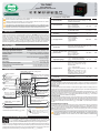
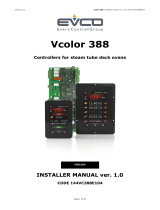
FRONT
Timer
OVEN TIME AND
TEMPERATURE CONTROLLER
TO-712B
Ver.03
Have this manual in your hand
using the FG Finder app.
6. OPERATION
1. DESCRIPTION
2. APPLICATIONS
5.1 Installation setup table
4. INTRODUCTION
5. INSTALLATION CONFIGURATION
3. TECHNICAL SPECIFICATIONS
Thermostat and timer for the automation of forced convection ovens. This model provides control over gas,
electric, or wood powered ovens, configured through the setup menu. TO-712B controls steam injection and
lighting in the oven, and has an internal audible alarm (buzzer) that signals, for example, the end of the roasting
process. It also allows for the use of an external audible alarm and the language selection of your main
messages, improving the user experience. The ThermON line is developed and produced with high-quality raw
materials and stands out for its unique and differentiated design and intuitive, user-friendly interface to facilitate
operation and configuration. It offers a functions lock feature to prevent third parties from changing the
parameters, air-tight front panel that provides high protection against the entry of dirt and moisture, and more.
SET
TO-712F
Quick touch: Increases parameter value
when in programming mode;
Upper display: Indicates the temperature
measured by the sensor or parameter
configuration;
Lower display: Indicates the cooking time or
parameter configuration;
Te m p e r a t u r e u n i t s L E D
indicator;
Q u i c k t o u c h :
Te m p e r a t u r e a n d
cooking time adjustment;
Press and Hold: Access to the
advanced configuration;
Quick touch: Turns the lightbulb
output on and off
Quick touch: Decreases
parameter value when in
programming mode ;
*Pr e s s a n d H o ld:
Turns the controller’s
stand-by on and off;
Quick touch: Steam activation;
Press and Hold: Steam activation
time adjustment;
Quick touch: Timer activation;
* When the stand-by mode is enabled ([I09] = YES)
Functions lock LED indicator;
Lightbulb output on LED
indicator;
Steam output on LED
indicator;
Timer activated LED
indicator;
Heating on indication
LED;
Ignition output on
indication LED;
SET
Each key has an LED to indicate its
function. When the LED is on, it
indicates that the key is active and
can be pressed.
KEY FUNCTIONS
SET
TECLA
LED
tc_J tc_H -tc_J
[i08]
Allows you to configure whether the digital
input will be used as an input for a door
sensor or as a digital input for high
temperature alarm:
[door] = Door sensor input;
[ALAr] = High temperature external alarm
input.
NOTE: When configured as a high
temperature alarm input, the other
functionalities related to the door sensor
consider that the door is always closed.
door Alar -door
Digital input mode
TO712BV03-02T-19303

ADJUSTMENT OF THE DESIRED TEMPERATURE (SETPOINT) OF
THE OVEN:
Defines the working temperature of the oven. This parameter can be adjusted between the
values defined in [F02] - Minimum value allowed to configure the oven temperature setpoint
and [F03] - Maximum value allowed to configure the oven temperature setpoint.
TIMER ADJUSTMENT:
Defines the cooking time. When the time expires, the audible alarm output is switched on
intermittently until any key on the controller’s front panel is pressed. The timer can be adjusted
between 00:01 and 99:59. The time scale is adjusted in parameter [F16] - Time base of the
timer.
NOTE: When the [,F13] - Disable timer function is set to [,YES], the timer setting will not
be available in this menu.
7.2 Steam activation
The steam operating mode is defined in parameter [F20] - Steam Operating Mode. Steam activation depends
on parameters [F22] - Time interval between steam activations and [F23] - Minimum temperature to activate
the steam, available in the advanced configuration menu. These conditions must be met for the injection of steam
in the oven to occur.
7.2.1 Steam activation times
Press the % key and hold for 4 seconds to adjust. Use the< and >keys to adjust the value of the parameter. To
confirm, perform a quick touch on the % key.
STEAM OUTPUT ON TIME:
This parameter can be adjusted between 1 and 30 seconds, and the factory default is 3
seconds.
STEAM OUTPUT OFF TIME:
This parameter can be adjusted between 1 and 600 minutes, and the factory default 5 is
minutes.
Note: This parameter is available for adjustement when the steam control mode selected is
cyclic, [F20]=[CYC,].
8.2 Parameters table
8.1 Changing the controller parameters
MIN
MIN
MAX
MAX
UNIT
UNIT
DEFA
DEFA
DESCRIPTION
DESCRIPTION
FUN
FUN
FUNCTION
FUNCTION
7.3 Functions lock
To enable / disable the function lock, press < and > and hold for the time configured in
parameter [F26] - Time for function lock.
When this configuration is active, the parameters cannot be changed, but they can be viewed.
When the lock is active, the parameters available for adjustment are defined in parameter
[F25] - Functions Lock.
Icon& indicates the status of the lock. Icon lit indicates the functions lock is active.
To enable the Default (standard) operating mode of the oven, the controller must be powered
up with the$and% keys pressed until the message appears on the display. This mode is
available when the type of oven selected is GAS. For more details about this operating mode
check item 6.4 Default Mode (standard).
7.4 Enable Default (standard) operating mode
IN THIS OPERATING MODE THE FLAME SENSOR IS IGNORED AND THE CONTROLLER WILL
NOT DETECT THE PRESENCE / LACK OF FLAME, BEING ESSENTIAL FOR THE OPERATOR TO
PAY SPECIAL ATTENTION TO THE CONTROL OF THE OVEN IN ORDER TO PREVENT GAS
ACCIDENTS.
7.5 STAND-BY Function
When function [I09]- standby oven functionality is set to YES, the controller can be put on standby at any
time by the user. This functionality allows for the control to be kept disabled (all outputs off). To put the controller
on stand-by mode, press> for approx. 4 seconds, until the message [OFF] is displayed. While the controller is
on stand-by, the display will flash the >key icon to indicate for the key to be pressed again for 4 seconds to
reactivate the oven control.
Use the < or > keys to select the desired function. The value can be edited with a quick touch on the dddd
key. Use the < or > keys to change the value and press the key with a quick touch when ready to save the
configured value and return to the functions menu. To leave the configuration menu and return to the normal
operating mode (temperature and time indication), press (long touch) until[----]is displayed.dddd
Access the advanced configuration menu by pressing the key for 4 seconds until dddd
[FuNc]is displayed. When [CoD] is displayed press the key again (quick touch). Use dddd
the < or > keys to enter the access code 123 and press (quick touch) again when dddd
ready.
SET
SET
8. OPERATIONS - ADVANCED LEVEL
SET
SET
SET
Access Code (123) Required when you want to change the
advanced configuration parameters.
[CoD] 0 9999 -0
Temperature sensor indication
offset:
Allows compensating deviations in the
sensor temperature reading.
[F01] -20
(-4)
20
(36)
°C
(°F)
0
(0)
These parameters serve as the lower and
upper thresholds for the adjustment of
parameter ‘’SP’’- oven temperature
setpo i nt. They are used to block
temperature adjustments and to avoid an
improper configuration for the operation of
the oven
Minimum value allowed to
c o n f i g u r e t h e o v e n
temperature setpoint
Maximum value allowed to
c o n f i g u r e t h e o v e n
temperature setpoint
[F02]
[F03]
-10
(14) F03 °C
(°F)
0
(32)
F02 500
(932)
°C
(°F)
230
(446)
Oven temperature differential
(Hysteresis)
The temperature difference to switch on
the heating output. This function allows
defining a temperature interval within wich
the heating output will remain off.
[F04] 1
(1)
20
(36)
ºC
(ºF)
3
(5)
D e l a y t o s w i t c h o f f t h e
temperature control when the
door of the oven is opened
Defines the delay to switch off the
temperature control when the oven door is
opened to allow furnishing the oven without
switching off the control. To disable this
function, change the adjustment to the
minimum until [no,]is displayed. In this
case, the temperature control is switched
off as soon as the door is opened.
[F05] no(0) 180 sec.
Number of attempts to light the
flame (GAS-FIRED OVEN)
Defines the maximum number of attempts
the controller will try to ignite the flame.
After using up all attempts, the controller
will signal error [ER5]-Out of Gas.
Note: This parameter is used when the
type of oven selected is GAS.
[f06] 15-
Ignition output on time (GAS-
FIRED OVEN)
Defines the time the ignition output will stay
switched on to try to ignite the flame.
Note: This parameter is used when the
type of oven selected is GAS.
[f07] 115 sec.
90
3
3
Delay to activation of the
i g n i t i o n o u t p u t a f t e r
controller start up (GAS-
FIRED OVEN)
Defines the delay to activate the ignition
output after the gas output is activated in
the first attempt to ignite the flame. This
time is used so that the gas from the
cylinder reaches the burner and then the
ignition is activated.
Note: This parameter is used when the
type of oven selected is GAS.
[F09] no
(0) 15 sec. 2
Interval between activations
of the ignition output (GAS-
FIRED OVEN)
Defines the interval between attempts to
activate the flame.
Note: This parameter is used when the
type of oven selected is GAS.
[f08] 115 sec. 5
Delay of the temperature
control after controller start
up (GAS-FIRED OVEN)
When the controller is powered up, the fan
is activated first and then the flame ignition
process commences after the time
adjusted in this parameter has elapsed.
Note: This parameter is used when the
type of oven selected is GAS.
[F10] no
(0) 30 sec. 15
The controller has easy access to resources that are relevant to the user of the oven.
7.1 Adjustment of oven temperature and timer
To adjust oven temperature and timer, perform a quick touch on the SET key. Use the < and > keys to adjust the
value of the parameter. To advance and / or terminate the adjustment, perform another quick touch on the SET
key.
7. OPERATIONS - BASIC LEVEL
Timer trigger mode
Defines the timer triggering mode:
[MAN]= Manual, through the $key or E2:
Remote timer trigger.
[INI]= Start up, when the controller is
powered up.
[TMP]=Temperature, when the oven
working temperature is reached.
Note: In modes [INI] and [TMP] the$
key only cancels the timer.
[F14] MAN TMP -MAN
Timer counting direction
Defines the direction the timer counts:
[DEC] = time count down.
[CRE] = time count up; DEC CRE -DEC
Delay of the temperature
control (GAS-FIRED OVEN)
When attempting to re-ignite the flame, for
example, the time set in this parameter
must be exceeded before starting the flame
ignition process.
Note: This parameter is used when the type
of oven selected is GAS.
[F11] no
(0) 30 sec. 5
Timer time base
Defines the time base of the timer:
[MM:SS]= minutes, maximum time 99:59
minutes;
[HH:MM] = hours, maximum time 99:59
hours;
[F16]
HH:MM
-
MM:SSMM:SS
Timer reset mode
Defines the timer reset mode, essentially
wheter the audible alarm will be switched
off manually or by time:
[MAN]=Manually through the$key or E2:
Remote timer trigger.
[AUT]=Automatically according to the
time defined in parameter [F19];
Note: The timer also resets when the door
of the oven is opened, independently of the
mode defined in this parameter.
[F15]
MAN AUT -MAN
Dis able s temperature
control at the end of the
timer
Allows you to deactivate the temperature
control at the end of the timer countdown.
However, the control will only be turned off if
the function [F13] - Disable timer is
configured as NO and the function [F14] -
Timer trip mode is configured as MANUAL,
to avoid an incorrect operation of the
temperature control;
[F12] NO YES -NO
[F13] Disable timer
It allows disabling the timer, not allowing
manual or automatic triggering. Neither the
timer icons nor the digits on the lower display
will be shown, only the parameter settings
and other controller messages.
NO YES -NO
[F17]

MIN MAX UNIT
DEFA
DESCRIPTION
FUN FUNCTION
Steam working mode
Defines the steam operating mode for the
selected preset [rCnF]:
[OFF,]Off: does not inject steam.
[MAN,]M anual: injects steam when the
%key is pressed.
[AUT,] Automatic: automatically injects
steam after the timer is activated. The
steam is activated after the time set in
[F21] has elapsed.
[CYC,]Cyclic: injects steam in cycles
using the times configured in [UAon] and
[Uaof].
OFF CYC -MAN
Delay to activate the
automatic steam
Defines the delay before injecting steam
into the oven after the timer is activated.
This parameter is valid when automatic
steam is adjusted in parameter [F20].
[f19]
1999 sec. 5
Time interval between
steam activations
Defines the minimum time interval between
steam activations, i.e. once the steam
output is activated, the controller will not
activate it again before the time adjusted in
this parameter has elapsed. To disable this
function, change the adjustment to the
minimum until [no,]is displayed.
Note: This parameter is disregarded when
the type of steam selected is cyclic.
[f20]
no(0) 30 min. no(0)
Minimum temperature to
activate the steam
Defines the minimum temperature in the
oven to allow activating the steam output.
To disable this function, change the
adjustment to the minimum until [no,]is
displayed.
[f21]
no(-10)
no(14)
500
(932)
ºC
(ºF)
Lightbulb on time
[f22]
no(0) 180 sec. 15
Defines the functions lock mode:
[OFF,]= functions lock disabled;
[LOC1]= partial functions lock 1 -
prev e n t s adva n c e d c o n figur a t i o n
parameters from being changed;
[FULL] = full functions lock, does not
allow any parameter adjustment;
Time for function lock
Defines the time to lock / unlock the
functions. For more information, see item
7.3 - Functions Lock.
[f26] 130 sec. 10
Functions lock
[f23]
-
OFF FULL -LOC1
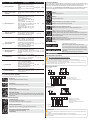
9. SIGNALING
Upon power up the controller indicates the operating mode of the oven.
9.1 Operating mode signaling
9.2 Programming signaling
Electric Oven
Controller configured with the electric oven logic.
Gas-fired Oven
Controller configured with the gas-fired oven logic.
Wood-fired Oven
Controller configured with the wood-fired oven logic.
Controller configured with gas-fired oven logic with Default (standard) mode enabled, without
flame sensor monitoring. For more information, see item 7.4 Enable Default (standard)
operating mode;
Defaul Mode (standard)
Functions lock active
Does not allow adjusting the parameter.
To deactivate functions lock, see item 7.3 - Functions lock.
Parameter adjustment denied
Enter access code in parameter [Cod]to adjust the parameter value.
Receiving data via EasyProg* (programming key)
Updating the parameter table via EasyProg*.
*sold separately
9.3 Process signaling
If the controller detects an error that interferes in the operation of the system, the controller switches off the
outputs, switches on the audible alarm intermittently, and indicates the detected failure on the display. T o l e a v e
error mode, the controller must be switched off, the fault corrected, and the controller switched on again.
Note: In case the [I09] - Enable stand-by oven functionality function has been set as YES, press the >key
during the error signaling to put the controller on stand-by and reboot it after the informed error is corrected.
Measure:
Contact Full Gauge Controls.
Measure:
Contact Full Gauge Controls.
Reason: Temperature sensor disconnected or out of range.
Measure: Check sensor connections and operation.
Reason: Flame sensor shorted with the burner.
Measure: Check wheter the flame sensor is making contact with the burner.
Sets the time to switch off the lightbulb
automatically after the key is pressed.dd
Note: If set to [no,], the lightbulb is
switched on / off with every touch of .dd
@
@
Reason: Out of gas, the controller does not detect a flame.
Measure: First check if there is gas available for the oven to operate.
Check the presence of flame and the distance between the flame sensor and the burner.
Other possibilities for this failure are: flame sensor disconnected or dirty / oxidized, damaged
ignition module or gas valve.
9.4 Other signaling
Indicates that the oven door is open.
Note: The message keeps flashing on the lower display.
Requests for the operator to close the oven door. Indicates that the
door remained open for the time configured in parameter F05. In
this mode the controller switches off the heating and activates the
audible alarm.
Note: The message keeps flashing on the lower display.
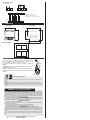
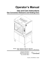
10.1.2 Oven: gas
PRECAUTIONS WHEN INSTALLING THE PRODUCT:
10.1.1 Oven: electric
Before performing any procedure on this instrument, disconnect it from the power grid;
Ensure that it has adequate ventilation, avoid installation on control panels containing devices that could
cause it to operate outside its specified temperature range;
Install the product away from sources that may generate electromagnetic disturbances, such as:
motors, contactors, relays, solenoid valves, etc.
IMPORTANT:
It is crucial to install the ignition module next to the burner and as far as possible from the electronic
controller;
The ignition electrode must be installed at a distance of 5 mm from the burner;
The flame sensor must be installed at a distance of 5 mm from the burner and at least 5 mm from the
ignition electrode.
10. INSTALLATION
10.1 Electrical connections
HH:MM
-
MM:SSMM:SS
Timer reset time base
Defines the time base when the timer is
reset:
[MM:SS]= minutes, maximum time 99:59
minutes;
[HH:MM]= hours, maximum time 99:59
hours;
[F18]
Time to reset the timer
(aut mode)
Defines the time to reset the timer if
automatic reset is selected in parameter
[F17].
0:01 99:59 F18 0:05
[f24]
[f25]
Reason: External high temperature alarm.
NOTE: Only when the [i08] function is configured as High temperature external alarm.
Measure: Check oven operation and temperature.
1234
11 12 13 14 15 16 17 18 19
5 6 7 8 910
Phase
Neutral
RESISTENCE
Thermocouple
J
LIGHT BULB
STEAM
E1
E1: Door micro switch
E2: Remote timer trigger
B1: External audible alarm (buzzer)
20
E2
B1
123 4
11 12 13 14 15 16 17 18 19
5 6 7 8 910
Phase
Neutral
GAS
Thermocouple
J
LIGHT BULB
IGNITION
STEAM
E1
E1: Door micro switch
E2: Remote timer trigger
E3: Flame sensor
B1: External audible alarm (buzzer)
Q: Burner
20
E2
E3
Q
B1
no(-10)
no(14)

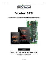
10.1.3 Oven: wood
12. EasyProg* - version 02 or later
11. DIMENSIONS
75,6
75,4
Panel openings
67,2 mm
67,2 mm
25 mm
10 mm
Packaging:
Materials used in the packaging of the Full Gauge products are 100% recyclable. Be sure to dispose of using specialized recycling
facilities.
Product:
The components used in the Full Gauge controllers may be recycled and reused if disassembled by specialized companies.
Disposal:
Do not incinerate or dispose of the controllers that reached the end of their service life in household waste. Be sure to comply with
the existing legislation in your area relating to disposal of electronic waste. In the event of doubt, please contact Full Gauge
Controls.
ENVIRONMENTAL INFORMATION
67
100,3
75
80
84,8
Side view
Front view
WARRANTY - FULL GAUGE CONTROLS
Products manufactured by Full Gauge Controls, as of May 2005, have a two (2) - year warranty directly with the factory and
one (1) year before the reseller network, counted as of the date of consigned sale as stated on the invoice. After this said year
before the reseller network, the warranty shall continue to be executed if the instrument is sent directly to Full Gauge Controls.
The products are warranted in case of defects in workmanship making them unsuitable or inadequate to the intended
applications. The warranty is limited to maintenance of instruments manufactured by Full Gauge Controls, disregarding other
kinds of expenses, such as indemnity for damages caused to other equipment.
EXCEPTIONS TO WARRANTY
The Warranty does not cover expenses incurred for freight and / or insurance for sending the products with signs of defect
or malfunctioning to the provider of technical support services. The following events are also excluded from warranty: natural
wear and tear of parts, external damages caused by falls or inadequate packaging of products.
INVALIDATION OF WARRANTY
The product warranty shall lose validity, automatically, if:
- The instructions for use and assembly contained in the technical description and the installation procedures described in
Standard NBR5410 are not followed;
- The product is submitted to conditions beyond the limits specified in its technical description;
- The product is violated or repaired by a person not integrating the technical team of Full Gauge;
- The damages are due to a fall, blow and / or impact, water damage, overload and / or atmospheric discharge.
USE OF WARRANTY
For use of the warranty, the customer should send the adequately packaged product, along with the respective Invoice to
Full Gauge Controls. The customer will bear the freight cost for sending of the products. Also, as much information as possible
with regard to the defect verified should be sent, in order to facilitate the analysis, the testing and the performance of the
service.
These processes and any product maintenance shall only be performed by the Technical Support Services of Full Gauge
Controls, at the Company headquarters - Street Júlio de Castilhos, 250 - CEP 92120-030 - Canoas - Rio Grande do Sul –
Brasil.
Rev. 03
Copyright 2022
It is an accessory the main function of which is to store the parameters of
controllers. At any time you can load new parameters of a controller and unload
them on a production line (of the same controller), for example.
It is provided with three types of connections for loading or unloading the
parameters:
- Serial RS-485: It is connected via RS-485 network to the controller (only for those
controllers provided with RS-485).
- USB: It is connected to the computer via USB port, using the Sitrad Preset Editor.
- Serial TTL: The controller may be connected directly to EasyProg via Serial TTL
connection.
EASYPROG
*sold separately
All rights reserved.
1234
11 12 13 14 15 16 17 18 19
5 6 7 8 910
Phase
Neutral
ALARM
Thermocouple
J
LIGHT BULB
STEAM
E1
E1: Door micro switch
E2: Remote timer trigger
B1: External audible alarm (buzzer)
20
E2
B1
-
 1
1
-
 2
2
-
 3
3
-
 4
4


Ask a question and I''ll find the answer in the document
Finding information in a document is now easier with AI
Related papers
-
Full Gauge Controls TO-711F User manual
-
-
-
-
-
-
-
-
-
Other documents
-
Baxter ML-132515 Operating instructions
-
 Evco EVCLC38FJ2E Installation guide
-
-
-
Hobart HO300G User manual
-
 Cleveland CR-32 DD User manual
-
 Evco EVCLC37DJ2E Installation guide
-
 Evco EVCLC37DJ2E Installation guide
-
Vulcan ABC7G User manual
-


