DAUDIN GFMS-RM01S User manual

Type
User manual

DAUDIN GFMS-RM01S is a Modbus RTU master module that can be used to connect and communicate with various remote I/O devices, such as digital input, digital output, and power supply modules. This enables the monitoring and control of industrial processes and equipment, providing real-time data acquisition and control capabilities. With its RS485 communication interface, the GFMS-RM01S can be easily integrated into existing industrial networks, allowing for seamless data exchange and centralized control.

DAUDIN GFMS-RM01S is a Modbus RTU master module that can be used to connect and communicate with various remote I/O devices, such as digital input, digital output, and power supply modules. This enables the monitoring and control of industrial processes and equipment, providing real-time data acquisition and control capabilities. With its RS485 communication interface, the GFMS-RM01S can be easily integrated into existing industrial networks, allowing for seamless data exchange and centralized control.

and FATEK HMI
Modbus RTU Connection
Operating Manual
2302EN
V2.0.0
2
Table of Contents
1. Remote I/O Module Configuration List ............................................................................... 3
1.1 Product Description.............................................................................................................. 3
2. FATEK HMI Connection Setup .......................................................................................... 4
2.1 FATEK HMI Hardware Connection .................................................................................... 4
2.2 FATEK HMI Connection Setup .......................................................................................... 5
3
1. Remote I/O Module Configuration List
Part No. Specification Description
GFMS-RM01S
Master Modbus RTU, 1 Port Main Controller
GFDI-RM01N Digital Input 16 Channel Digital Input
GFDO-RM01N
Digital Output 16 Channel / 0.5A Digital Output
GFPS-0202 Power 24V / 48W Power Supply
GFPS-0303 Power 5V / 20W Power Supply
0170-0101 8 pin RJ45 female connector/RS-485 Interface Interface Module
1.1 Product Description
I. The interface module is used externally to convert FATEK HMI RS485’s
communication port (Modbus RTU) to a RJ45 connector
II. The main controller is in charge of the management and dynamic configuration of
I/O parameters and so on.
III. The power module and interface module are standard for remote I/Os and users
can choose the model or brand they prefer.
4
2. FATEK HMI Connection Setup
This chapter explains how to use the FvDesigner program to connect FATEK HMI
with .For detailed information, please refer to FATEK FvDesigner User Manual
2.1 FATEK HMI Hardware Connection
I. The connection port is at the bottom of the machine. Take P5070N for example. It
uses COM3 (RS485 pin)
PIN#
COM3
(RS-422)
COM3
(RS-485)
COM4
1
DATA+
2
DATA-
3
ISO_GND
ISO_GND
ISO_GND
4
RX+
5
RX-
6
TX+
DATA+
7
TX-
DATA-
II. Connect the COM (RS485 6/7) at the bottom of the machine to the interface module
(1/2) to convert it into a RJ45 connector, which will be connected to the main
controller
5
2.2 FATEK HMI Connection Setup
I. Launch FvDesigner, open a new file, select the controller page and then click on
“Add”
II. Or you can click to open an existing file, select “Project Management” page and then
click on “Connect”
6
III. Connection method setup
Notes:
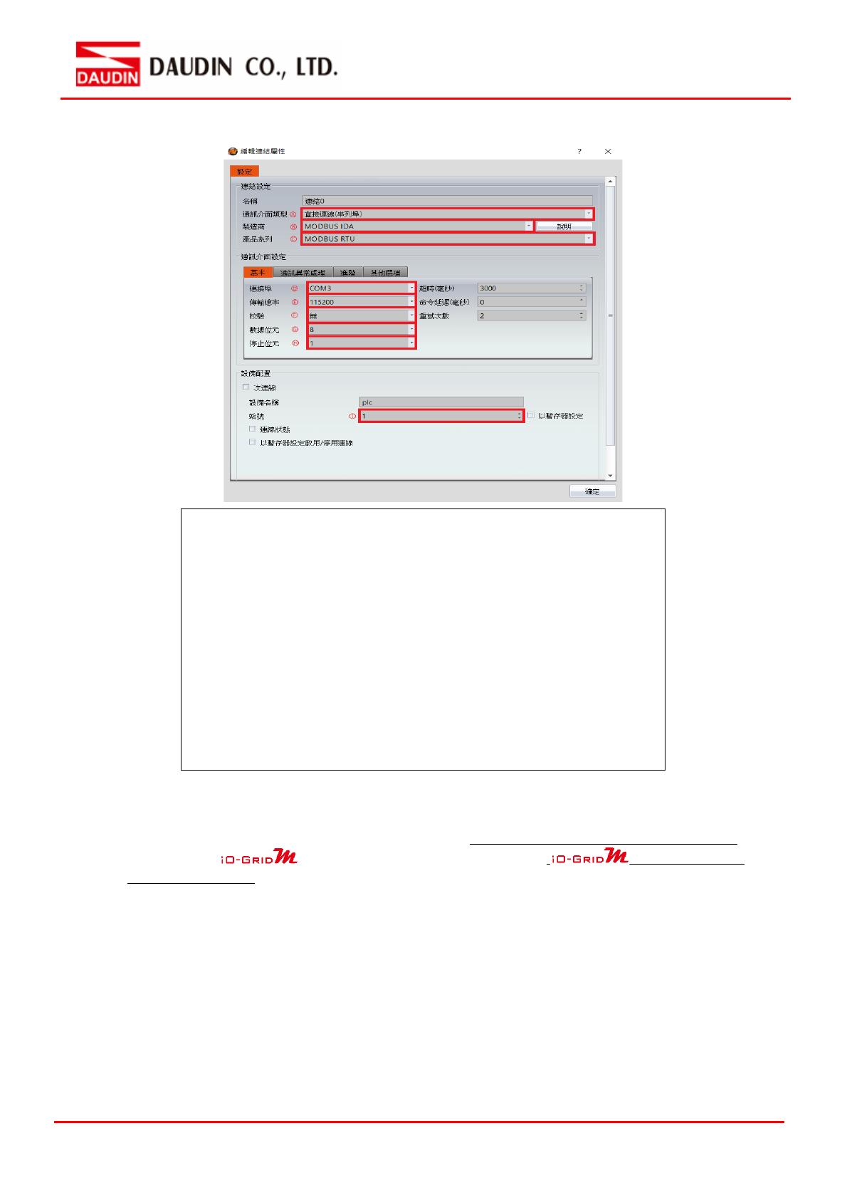
※The demonstration in the Connection Operating Manual uses COM3.
For using 485 pin with COM3, please refer to 2.1FATEK HMI Hardware Connection
※Regarding ’s parameter settings, please refer to
Control Module
Operating Manual
From the “Communication Interface Type” drop-down menu,
select ”Connect Directly (Serial Port)”
From the “Manufacturer” drop-down menu, select ”MODBUS IDA”
From the “Product Series” drop-down menu, select ”MODBUS RTU
From the “Connection Port” drop-down menu, select ”COM3
From the “Transmission Rate” drop-down menu, select “115200”
From the “Calibrate” drop-down menu, select “No”
From the “Data Bits” drop-down menu, select “8”
From the “Stop Bits” drop-down menu, select “1”
Set up based on the device
7
IV. Set up the location for the tag register
From the "Device” drop-down menu, select the device to be connected
From the “Type” drop-down menu, select “4x”
Set up according to the plan
Example:
Note:
※HMI's corresponding address:
’s first GFDI-RM01N has the register address at 1000(HEX) converted to
4096(DEC)+1
’s first GFDO-RM01N has the register address at 2000(HEX) converted to
8192(DEC)+1
※Regarding ’s register address and format, please refer to
Control
Module Operating Manual
register address
HMI’s corresponding address*
R
0x1000
4097
R
0x1001
4098
R
0x1000.0
4097.0
W
0x2000
8193
W
0x2001
8194
W
0x2000.0
8193.0
  • Page 1 1
  • Page 2 2
  • Page 3 3
  • Page 4 4
  • Page 5 5
  • Page 6 6
  • Page 7 7

DAUDIN GFMS-RM01S User manual

Type
User manual

DAUDIN GFMS-RM01S is a Modbus RTU master module that can be used to connect and communicate with various remote I/O devices, such as digital input, digital output, and power supply modules. This enables the monitoring and control of industrial processes and equipment, providing real-time data acquisition and control capabilities. With its RS485 communication interface, the GFMS-RM01S can be easily integrated into existing industrial networks, allowing for seamless data exchange and centralized control.

Ask a question and I''ll find the answer in the document

Finding information in a document is now easier with AI