Page is loading ...

Application Note J Pilots and K Thermocouples
Issue Date September 11, 2017
Pilot Burners/Thermocouples
© 2017 BASO Gas Products 1
Part No. BASO-AN-PB/THERMOCOUPLES, Rev. B www.baso.com
Pilot Burners/Thermocouples
Applications
This document is intended to aid the appliance
engineer or authorized service contractor in making a
standing pilot application. Pilot burners are
manufactured with a variety of tips and mounting
configurations. Representative types of mounting with
standard pilots are illustrated in Figure 1. Dimensions
shown are approximate and may vary, provided the
requirements of good ignition are met. See Good
Practice Rules.
Good Practice Rules
The following are good practice rules for governing the
location of the pilot:
Locate the pilot so that it can be reached
easily for lighting.
Locate the pilot in a position that has a fixed
relation to the main burner (see Figure 1).
Locate the pilot burner in a position that will
receive incoming air and not products of
combustion from the main burner. The pilot
should be located where it will not be affected
by an excessive draft of incoming air.
Locate the pilot burner in such a position that it
does not receive the full force of igniting or
extinguishing puffs from the main burner.
Locate the pilot burner in a position that will
allow ready removal for cleaning.
After Installation
When the pilot burner has been installed, carefully
make the following observations and tests:
1. Ensure the main burner flames do not impinge on
any part of the pilot burner.
2. Ensure the pilot burner will ignite the main burner
under all pilot burner conditions that maintain the
safety shutoff device (BASO) in the On position.
(See the Safety Turn Down Test section.)
3. Ensure the pilot burner will not be smothered out
or snuffed out:
when the main burner is ignited from a cold
start.
when the main burner is ignited with the
appliance at the maximum temperature
conditions of operation.
with normal variation in air adjustments of the
main burner.
with rapid Off and On operation of the main
burner with the combustion chamber cold.
with rapid Off and On operation of the main
burner with the combustion chamber hot.
with continued operation of the main burner.
4. To ensure proper operation, the pilot flame must
produce a satisfactory millivoltage as described in
the Thermocouple Output Test section.
Note: When a pilot is to be applied to an
appliance already in the field, obtain the appliance
manufacturer’s recommendations for the correct pilot
specification and location dimensions for the particular
model appliance.

Pilot Burners/Thermocouples
© 2017 BASO Gas Products 2
Part No. BASO-AN-PB/THERMOCOUPLES, Rev. B www.baso.com
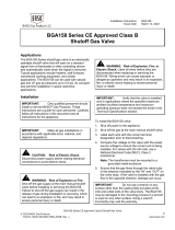
J999MKA-2* J999MYA-2* J999MHA-2*
J991MDA-2**, J993MDA-2**
J995MDA-2**, J997MDA-2** J992MDA-2**
J996MDA-2** J994MDA-2**
J998MDA-2**
J990MDA-2**
45o
* Mount pilot ignition port 3/8 in. (9.53 mm) above and 1/4 in. (6.35 mm) away from the center of nearest burner port.
** Mount pilot ignition port 1/4 in. (6.35 mm) above and 1/4 in. (6.35 mm) away from the center of nearest burner port.
Figure 1: Pilot Location
Thermocouple Output Test
When the pilot is applied properly, the thermocouple
will produce an open circuit millivoltage as shown in
Table 1. Normal operating voltages, as shown, must
be obtained to give trouble-free performance. Perform
the following tests with the Y99AB Test Kit.
Instructions for Testing BASO Pilot Burners with
K14, K15, K16, K17 and K19 Thermocouples
Attach the proper junction terminal of the millivoltmeter
to the thermocouple lead and measure the open
circuit voltage. Allow at least five minutes for each
meter reading. For specifications, see Table 1.
Table 1: Thermocouple Output Table
Thermocouple
mV Range
Lead
Type
Turn
Down
Normal
Not Less
Than
K14
4 mV
20-28
15
K15
4 mV
20-28
15
K16
4 mV
25-35
17
K17
4 mV
30-40
25
K19
4 mV
25-35
17
Safety Turn Down Test
!
WARNING: Risk of Explosion or Fire.
Avoid accumulation of unburned gas and resulting
personal injury or properly damage by making sure
the main burner lights under all pilot burner flame
conditions that maintain the BASO in the On
position. Follow the procedure below to assure the
location of the pilot with respect to the main burner is
acceptable.
Turn Down Test with the Use of the Y99AB Test Kit
To perform the turn down test with the Y99AB Test Kit
(purchasable from your BASO Gas Products
authorized wholesaler):
1. Disconnect the thermocouple from the BASO
safety shutoff device and connect it to the test kit
(see Figure 2). Hold the BASO in the open
position during this test using battery power from
the test kit.
Figure 2: Using the Y99AB for the Turn Down Test
2. Reduce the flame on the pilot through the use of
the “B” valve to the point where the open circuit
millivoltage reading is not more than
4 millivolts.

Pilot Burners/Thermocouples
© 2017 BASO Gas Products 3
Part No. BASO-AN-PB/THERMOCOUPLES, Rev. B www.baso.com
3. Cycle the main burner On and Off at least three
times. The main burner must ignite each time
within four seconds.
Thermocouple
Lead
Reset
Button
Pilot Burner
Gas Line
Thermostat
y99ab
BASO
Power Unit
Manual
Pilot
Button
Manual
Main
Valve
44549-7
44549-8
Actuator
Red Black
MILLIVOLTS
D.C.
PENN -BASO CONTRO LS
0
10
20
30
40
50
100
300
500
700
900
MILLIAMPS
0-500
MILLIVOLTS
0-1000 0-50
ADJUST
MILLIVOLTS
MILLIAMPS
Power
Source
Figure 2: Using the Y99AB for the Turn Down Test
Turn Down Test without Instruments
If you cannot secure ignition of the main burner when
the millivoltage reading is 4 millivolts, the pilot has
been located improperly with respect to the main
burner. Relocate the pilot; repeat Steps 2 and 3.
If you do not have the Y99AB Test Kit, perform the
turn down test using the following steps:
1. Reduce the flame on the pilot, through the use of
the “B” valve to a point where the pilot flame does
not impinge on the thermocouple (see Figure 3).
2. Cycle the main burner On and Off at least three
times. The main burner must ignite each time
within four seconds.
3. Wait at least three minutes for the BASO to drop
out. (Main burner flame will go out.)
4. If the BASO does not drop out, reduce the pilot
flame further and repeat Steps 2 and 3.
5. If you cannot secure ignition of the main burner
when the pilot flame has been reduced to the pilot
at which the BASO drops out, the pilot has been
located too far from the main burner and must be
moved closer. Repeat Steps 2, 3, and 4.
4.
This flame must ignite main
burner as long as . . .
. . . This flame keeps
BASO On.
Inlet Fitting
Marking
burnflam
Figure 3: Turn Down Test without Instruments
Observe the pilot flame under the various test
conditions and ensure it appears stable at all times.
Use a millivolt meter to determine the stability of the
pilot flame. During the observation, or test of pilot
performance, position the doors of the appliance in
their normal operating position.
Good pilot operation can be affected by many draft
conditions, appliance design, and recirculation of
combustion products.

Pilot Burners/Thermocouples
© 2017 BASO Gas Products 4
Part No. BASO-AN-PB/THERMOCOUPLES, Rev. B www.baso.com
Technical Specifications
Product
J Series BASSO Replacement Pilot Burners
Materials
Mounting Bracket
Plated Steel
Pilot Tip
430 Stainless
Pilot Body
Plated Steel
Inlet Tip
Aluminum
Inlet Body
Brass
Maximum Temperature
Mounting Bracket
825F (441C)
Pilot Tip
1500F (816C),(D Tip 1350F (732C)
Pilot Body
825F (441C)
Inlet Tip
635F (335C)
Inlet Body
750F (399C0
Agency Listings
None
Specification Standards
ANSI Z21.20
CAN 1-6.4
CAN/CSA-C22.2 No. 199-M89
Performance specifications are nominal and conform to acceptable industry standards. All agency certification of BASO products is performed
under dry and controlled indoor environmental conditions. Use of BASO products beyond these conditions is not recommended and may void
the warranty. Product must be protected if exposed to water (dripping, spraying, rain, etc.) or other harsh environments. The original
equipment manufacturer or end user is responsible for the correct application of BASO products. Consult BASO Gas Products LLC for
questionable applications. BASO Gas Products LLC shall not be liable for damages or product malfunctions resulting from misapplication or
misuse of its products.
Refer to the J Series Pilot Burners/Y90 Series Inlet Fittings Product Bulletin (BASO-PB-PILOTS/Y90) for necessary information on operating
and performance specifications for this product.
Technical Specifications
Product
K Series Thermocouples
Types of Gas
Natural, Liquefied Petroleum (LP), Manufactured, Mixed, or LP Gas-Air Mixture
Maximum Temperature
Hot Junction
1400F (K14), 1500F (K15, K16) and 1300F (K17, K19)
Cold Junction
850F
Copper Tube
640F
Termination
300F
Inlet Body
Brass
Storage Temperature
-40 to 176F (-40 to 80C)
Packaging
Bulk pack supplied to original equipment manufacturer, (individual pack optional)
Bulk Pack Quantity
100
Bulk Pack Weight
Varies due to the different lengths of leads
Agency Listings
CSA Certificate Number 229521-1656071
Specification Standards
ANSI Z21.20
CAN 1-6.4
CAN/CSA-C22.2 No. 199-M89
Performance specifications are nominal and conform to acceptable industry standards. All agency certification of BASO products is performed
under dry and controlled indoor environmental conditions. Use of BASO products beyond these conditions is not recommended and may void
the warranty. Product must be protected if exposed to water (dripping, spraying, rain, etc.) or other harsh environments. The original
equipment manufacturer or end user is responsible for the correct application of BASO products. Consult BASO Gas Products LLC for
questionable applications. BASO Gas Products LLC shall not be liable for damages or product malfunctions resulting from misapplication or
misuse of its products.
450 East Horseshoe Road
PO Box 170
Watertown, WI 53094 www.baso.com
1-877-227-6427 (1-877-BASOGAS Published in U.S.A.
/