Version 1.5 (Dec. 21, 2015)
Model PRS10
Rubidium Frequency Standard
Operation and Service Manual
1290-D Reamwood Avenue
Sunnyvale, California 94089
Phone: (408) 744-9040 • Fax: (408) 744-9049
email: info@thinkSRS.com • www.thinkSRS.com
Copyright © 2002, 2013, 2015 by Stanford Research Systems, Inc.
All Rights Reserved.

PRS10 Rubidium Frequency Standard

Table of Contents 1
PRS10 Rubidium Frequency Standard
Introduction 3
Specifications 4
Abridged Command List 5
Theoretical Overview 8
Rubidium Frequency Standards 8
PRS10 Overview 11
Block Diagram 11
Ovenized Oscillator 11
Frequency Synthesizer 11
Physics Package 13
Control Algorithm 13
Initial Locking 14
Locking to External 1pps 14
CPU Tasks 18
Applications 19
Interface Connector 19
Configuration Notes 19
Hardware Notes 20
Operating Temperature 21
Frequency Adjustment 21
RS-232 Instruction Set 22
Syntax 22
Initialization 22
Frequency Lock-loop Parameters 24
Frequency Synthesizer Control 28
Magnetic field Control 29
Frequency Control 31
One pulse per second control 31
1PPS Locking Control 33
Analog Control 36
Analog Test Voltages 37
Status Bytes 38
Calibration Procedures 41
Circuit Description 42
Schematic RB_F1 (sheet 1 of 6) 42
Input Power 42
Voltage Reference 42
Crystal Oscillator 42
Crystal Heater 44
Schematic RB_F2 (Sheet 2 of 6) 44
Temperature Control Servos 44
Conversion to 10MHz TTL 45
Photocell Amplifier 46
Signal Filters for Oscillator Control 47
Analog Multiplexers 47
Schematic RB_F3 (Sheet 3 of 6) 48
Microcontroller 48
RS-232 50
12 Bit A/D Conversion 50
12-Bit Digital to Analog Converters 50
Magnetic Field Control 50
Phase Modulation 51
1PPS Output 51
1PPS Input Time-Tag 51
Schematic RB_F4. (Sheet 4 of 6) 52
High Resolution, Low Phase Noise,
RF Synthesizer 52
RF Output Amplifier 53
Step Recovery Diode Matching 53
Analog Control 54
Schematic RB_F5 (Sheet 5 of 6) 54
Power Supply, Lamp Control and
1PPS Timing PCB 54
Linear Power Supplies 54
Lamp Regulator 55
1PPS Input Time-Tag 55
1PPS Output Pulse Delay 56
Baseplate Temperature Sensor 57
Schematic RB_F6 (Sheet 6 of 6) 57
Resonance Cell and Lamp Heaters 57
Resonance Cell 57
Discharge Lamp 57
Schematic RB_F7 (Sheet 1 of 1) 59
Connector Interface Board 59
Appendix A: Frequency Synthesizer
Table 60
Appendix B: Precision Frequency
Measurement 62
Set-up for an SR620 63
Four input connections: 63

2 Table of Contents
PRS10 Rubidium Frequency Standard
Four input setups: 63
“Coarse” Frequency
Measurements 63
“Fine” Frequency
Measurements 63
Parts List for Revision H 65

Introduction 3
PRS10 Rubidium Frequency Standard
PRS10 Rubidium Frequency Standard Introduction
The PRS10 is a ultra-low noise 10 MHz frequency standard which disciplines an SC-cut
ovenized oscillator to a hyperfine transition in the ground state of rubidium.
The PRS10 was designed to fill a variety of communication, synchronization, and
instrumentation requirements. The phase noise of the 10 MHz output is low enough to be
used as the reference source for cellular synthesizers. The unit’s short-term stability and low
environmental coefficients make it an ideal component in network synchronization systems.
Also, the low aging rate makes it an excellent choice as a timebase for precision frequency
measurements.
The unit is compatible in fit, form, and function to the Efratom FRS frequency standards,
with improvements in features and performance. The PRS10 allows closed case diagnostics
and calibration via an RS-232 interface, its digital synchronous detection and filtering
eliminate spurs on the 10 MHz output, and the PRS10 has 1000x less phase noise than the
Efratom unit (-130 dBc vs. –90 dBc at 10 Hz).
The PRS10 can time-tag an external 1pps input with very high resolution. These values may
be reported back via RS-232 and/or used to phase lock the unit to an external reference (such
as GPS) with a time-constant of several hours. This feature can provide Stratum 1
performance at a very low cost.
In addition to reading time-tag results, the RS-232 interface allows the user to set the
frequency, adjust the phase of the 1pps output, read the value of virtually every parameter
(lamp drive level, rf level, temperature set point of the crystal, lamp, and resonance cell, and
10 MHz output level) and measure many “test-points” (lamp light level, heater currents,
power supply voltages, and case temperature.)
The PRS10 establishes a new level of features and performance in atomic frequency
standards. Its design provides for the lowest phase noise and easiest path to system
integration of any rubidium frequency standard available.

4 Specifications
PRS10 Rubidium Frequency Standard
Units
Output
Frequency
10 (Sine wave into 50Ω)
MHz
Amplitude
0.5 ± 10% (about 1.41Vpp or +7 dBm)
Vrms
Accuracy
±5x10-11 (at shipment)
∆f/f
Allan variance
< 2x10-11(1s), < 1x10-11(10s), < 2x10-12(100s)
∆f/f
SSB phase noise
<-130 (10Hz), <-140 (100Hz), <-150 (1kHz)
dBc/Hz
Spurious
<-130 (100kHz B.W.)
dBc
Harmonics
<-25
dBc
Aging (after 30 days)
<5x10-11 (monthly)
<5x10⁻¹⁰ (yearly)
∆f/f
∆f/f
Return loss
> 25 (at 10MHz)
dB
Temperature
±1x10⁻¹⁰ over -20°C to +65°C baseplate
∆f/f
Voltage
< 2x10-11 for a 1Vdc supply change
∆f/f
Magnetic field
< 2x10⁻¹⁰ for 1 Gauss field reversal
∆f/f
Retrace
±5x10-11 (72 hr off then 72 hr on)
∆f/f
Settability
< 5x10-12
∆f/f
Trim Range
±2x10⁻⁹
∆f/f
Time to lock
< 6 (starting at 25°C)
minutes
Time to 1x10⁻⁹
< 7 (starting at 25°C)
minutes
Other Electrical
Power supply
+24.0 (nom), +22 (min), +30 (max)
Vdc
Supply current
2.2 (warmup) , 0.6 (steady-state at 25°C)
A
Protection
± 30 (to any pin except rf output)
Vdc
RF protection
100 (stable with any termination)
mA
Ext calibration
0-5.00
Vdc
Cal reference out
5.00 ± 0.05
Vdc
RS-232
9600 (8 bits, no parity, 1 stop bit, 0V/5V levels with x
on/x off protocol)
baud
1pps measurement
±10 (accuracy), 1 (resolution)
ns
1pps output set
±10 (accuracy), 1 (resolution)
ns
Miscellaneous
Temperature
-20 to +65 (baseplate)
°C
Storage
-55 to +85
°C
Size
2.00 x 3.00 x 4.00
inches
Weight
1.32
lbs
Warranty
1
year
Baseplate threads
4-40 (4 places)
Connector
Mates with ITT/Cannon DAM11W1S series

Abridged Command List 5
PRS10 Rubidium Frequency Standard
Abridged Command List
Commands consist of two-letter ASCII mnemonics. A command may be followed one or
more numeric values, and punctuation. Command sequences end with a carriage return
(ASCII 1310). All commands are case insensitive. Spaces (ASCII 3210) and linefeeds (ASCII
1010) are ignored.
A command followed by a value is used to set a parameter to the value. A command
followed by an exclamation point (! or ASCII 3310) indicates that the current value should be
saved to EEPROM to be used as the initial value after the next reset. A command followed
by a question mark (? or ASCII 6310) is used to request that the current value be returned. A
command followed by an exclamation point and a question mark is used to return the
EEPROM value.
For example, the gain parameter determines the time constant used to lock the 10MHz
oscillator to the rubidium hyperfine transition. Examples of the four forms of the gain
parameter command are:
GA? ;returns the current value of the frequency lock loop gain parameter.
GA7 ;sets the frequency lock loop gain parameter to 7.
GA! ;writes the value of the gain parameter to EEPROM for use after reset.
GA!? ;returns the value of the gain parameter which is stored in EEPROM.
All strings returned by the unit are terminated with a carriage return (ASCII 1310). In the
verbose mode, strings are preceded with a linefeed (ASCII 1010) and terminated with a
carriage return and a linefeed. If more than one value is returned by a command the values
will be separated by a comma (ASCII 4410).
When a unit is first turned “on”, it will send the string “PRS_10” (without the quotes)
followed by a carriage return.
Only commands in bold type are available to the end-user. The other commands are “factory
only” commands which disabled at the factory.

6 Abridged Command List
PRS10 Rubidium Frequency Standard
Query
Value
Set Value or
Activate
Write
EEPROM
Query
EEPROM
Description
Initialize
RS? RS 1 Restart
VB? VB value Verbose mode
ID? Read ID string
SN? SN value SN! SN!? Read unit serial number
ST? Read six status values
LM? LM value LM! LM!? Lock pin mode
RC 1
RC! Recall factory calibration
Freq. Lock
LO? LO value Frequency lock loop status
FC? FC high,low FC! FC!? Frequency control values
DS? Read detected signals (ω and 2ω)
SF? SF value Set frequency offset
SS? SS value SS! SS!? Set Slope (SF calibration)
GA? GA value GA! GA!? FLL Gain parameter
PH? PH value PH! PH!? Phase angle parameter
SP? SP r,n,a SP! SP!?
Set synthesizer parameters
Magnetic
Tuning
MS? MS value Magnetic switching
MO? MO value MO! MO!? Magnetic Offset
MR? Magnet read
1PPS Lock
TT? Time-tag (1pps input)
TS? TS value TS! TS!? Time slope cal. (1pps input)
TO? TO value TO! TO!? Time-tag offset
PP value Place pulse (1pps output)
PS? PS value PS! PS!? Pulse slope cal. (1pps output)
PL? PL value PL! PL!? Phase lock (to 1pps input)
PT? PT value PT! PT!? Phase lock time constant
PF? PF value PF! PF!? Phase lock stability factor
PI? PI value Phase lock integral term

Abridged Command List 7
PRS10 Rubidium Frequency Standard
Query
Value
Set Value Write
EEPROM
Query
EEPROM
Description
D/A Control
SD0? SD0,value SD0! SD0!? Set DAC (RF amplitude)
SD1? SD1,value SD1! SD1!? Set DAC (1pps delay)
SD2? SD2,value SD2! SD2!? Set DAC (lamp intensity)
SD3? SD3,value SD3! SD3!? Set DAC (lamp temperature)
SD4? SD4,value SD4! SD4!? Set DAC (crystal temperature)
SD5? SD5,value SD5! SD5!? Set DAC (cell temperature)
SD6? SD6,value SD6! SD6!? Set DAC (10 MHz amplitude)
SD7? SD7,value SD7! SD7!? Set DAC (RF deviation)
Analog Test (12-bit
values)
AD0? Spare (J204)
AD1? +24V(heater supply) / 10.
AD2? +24V(electronics supply) /10
AD3? Drain voltage to lamp FET / 10
AD4? Gate voltage to lamp FET / 10
AD5? Crystal heater control voltage
AD6? Resonance cell heater control
AD7? Discharge lamp heater control
AD8? Amplified ac photosignal
AD9? Photocell’s I/V converter / 4
AD10? Case temperature (10 mV/°C)
AD11? Crystal thermistors
AD12? Cell thermistors
AD13? Lamp thermistors
AD14? Frequency calibration pot
AD15? Analog ground
Analog Test (8bit values)
AD16? VCXO varactor voltage
AD17? VCO varactor voltage
AD18? AGC for RF
AD19? RF PLL lock signal

8 Theoretical Overview
PRS10 Rubidium Frequency Standard
Theoretical Overview of Rubidium Frequency Standards
Rubidium is an alkali metal (like lithium, sodium, potassium and cesium). There are two
naturally occurring isotopes of rubidium, Rb85 and Rb87, which have relative abundances of
72% and 28% respectively. The metal has a melting point of 39°C.
The alkali metals behave similarly: they have one electron outside an inert core. Most of the
chemical, electronic and spectroscopic properties of these elements are determined by this
outer electron. The deep red glow of a low power rubidium discharge lamp is due to the
resonance line transitions of the outer electron as it emits a red photon and drops back to the
ground state.
The ground state of Rb87 is split by a very small energy due to the relative orientation of the
magnetic spins of the electron and the nucleus. The split corresponds to the energy of a
photon with a (microwave) frequency of 6.834,682,612,8 GHz. It is this hyperfine transition
frequency which will be used to stabilize the 10 MHz output of the PRS10.
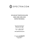
To see how this is might be done, Figure 1 shows a typical physics package which uses a
discharge lamp, an isotopic filter, and a resonance cell. We will see that the amount of light
which passes through the resonance cell to the photodetector can be reduced when the
resonance cell is exposed to microwaves at the hyperfine transition frequency.
To simplify the discussion, we will assume that the light from the Rb87 discharge lamp
consists of just two lines corresponding to transitions from a single excited state to the split
ground state. The filter cell contains Rb85 vapor which also has a split ground state and an
isotopic shift (relative to Rb87) as well. An important coincidence exists: one of the lines
from the Rb87 discharge corresponds one of the transitions in Rb85. This will allow us to
reduce the intensity of this line by passing the Rb87 discharge light through the Rb85 vapor.
Normally, atoms in the ground state will be equally distributed between the split states, as the
splitting is much less than the thermal energy of the atoms in the vapor. This distribution is
modified by the filtered light from the discharge, by a process called “optical pumping”.
Suppose that the filter can completely remove one of the two discharge lines. The remaining
light can be absorbed by Rb87 atoms in the resonance cell which are in the lower ground
state, moving them to the upper state. When they decay from the upper state, they fall with
equal probability into either ground state. As this continues, population will be moved from
the lower ground state to the upper ground state, circulating through the upper state. As the
population in the lower ground state is decreased, the amount of light which reaches the
photodetector will increase, as the number of atoms which can absorb the radiation is
reduced.

Theoretical Overview 9
PRS10 Rubidium Frequency Standard
Now, if we apply a microwave field at the frequency corresponding to the hyperfine
transition frequency (6.834,682,612,8 GHz), the populations in the ground state will mix, and
the amount of light reaching the photodetector will decrease.
The PRS10 uses the “integrated filter” topology: rather than a separate filter cell, the
resonance cell contains a mixture of the two rubidium isotopes, along with a buffer gas. The
lamp also contains a mixture of isotopes. The isotopic mixtures, buffer gases, and operating
conditions are chosen so as to minimize temperature coefficients and intensity shifts of the
apparent hyperfine transition frequency.
Rb87
Discharge
lamp
RF @ 6.834GHz
5p
Rb87
Emission
Rb87
Optical
Pumping
Rb85
Scattering
6,834,682,612.8Hz
Rb85 Isotopic
Filter
Rb87
Resonance
Cell
Photocell
Figure 1. Hypothetical Rubidium Physics Package
5s
≅780nm
Photons

10 Theoretical Overview
PRS10 Rubidium Frequency Standard
The apparent transition frequency will be shifted by about 3 kHz from the natural transition
frequency by the buffer gas and discharge lamp spectral profile. The transition frequency
differs slightly for each unit, depending on the fill pressure, etc. The transition frequency is
also tuned over a few Hertz by a magnetic field which may be varied.
In the PRS10, the rubidium physics package acts as a very stable frequency detector for a
frequency around 6.834 GHz. By using a microwave frequency synthesizer which is
referenced to the 10 MHz OCXO, the 10 MHz may be stabilized to the rubidium hyperfine
transition frequency.

PRS10 Overview 11
PRS10 Rubidium Frequency Standard
PRS10 Overview
All compact rubidium frequency standards discipline a crystal oscillator to the hyperfine
transition frequency in the ground state of rubidium. Several different topologies have been
developed. A major difference in these designs is the method chosen to lock a standard
output frequency (usually 10 MHz) to the (essentially arbitrary) hyperfine transition
frequency at about 6.834 GHz.
Block Diagram
Figure 2 shows a block diagram for the PRS10 Rubidium Frequency Standard. The design of
the PRS10 is quite different from other rubidium frequency standards leading to several
feature and performance benefits.
Ovenized Oscillator
The output from PRS10 comes directly from a 10 MHz oven stabilized, 3rd overtone,
varactor tuned, SC-cut crystal oscillator. The varactor is tuned by a 22bit digital-to-analog
converter which provides a full scale tuning range of ±2 ppm. The very fine step size
(≈1:10-12) maintains the low noise inherent to the SC-cut resonator, yet the full-scale range is
sufficient to compensate for crystal aging over the lifetime of the unit. This approach
provides a 10 MHz output with extremely low phase noise which is virtually free of spurs.
Frequency Synthesizer
The 10 MHz also serves as the reference source to the frequency synthesizer which generates
RF at about 359.72 MHz. The RF is multiplied by a factor of 19x in a step recovery diode to
provide the microwave frequency (at about 6.834 GHz) which is used to interrogate the
physics package. (The apparent hyperfine transition frequency varies with each physic
package due to variations in buffer gas fill pressure, etc.)
The frequency synthesizer has two important characteristics: a step size of about 1:10-9 and
very low phase noise output. The small step size is required so that only small magnetic
fields will be needed to tune the apparent hyperfine transition frequency between the steps of
the synthesizer. The low phase noise is required so as not to degrade the signal from the
physics package, which would lead to a noisy frequency lock, and degraded output stability.
These two characteristics require a dual loop design for the frequency synthesizer. The inner
loop consists of the 359.72 MHz VCO which is directly phase locked to a 3rd overtone
22.48252 MHz crystal oscillator. This loop has a large natural frequency of about 400,000r/s.
The VCO’s phase noise at 359.72 MHz is very close to the phase noise of the crystal (plus 24
dB for the multiplication factor of 16).

12 PRS10 Overview
PRS10 Rubidium Frequency Standard
The outer loop compares the RF frequency to the 10 MHz. This loop provides high resolution
by dividing the RF and 10 MHz by large numbers, and consequently operates at a low
comparison rate (typically 4 kHz). This loop has a low natural frequency (about 10 r/s) so the
phase noise of the RF more than a few Hz from carrier will be determined by the inner loop.
The outer loop slowly disciplines the frequency of the inner loop’s crystal, keeping it locked
to the 10 MHz reference.
Figure 2. Rubidium Frequency Standard Block Diagram
Data
to
CPU
Step Recovery Diode
Matching
Transformer
50Ω
Output
10MHz Low Noise
Ovenized Oscillato
r
22-bit DAC
(
10-12 /bit
)
22.4825MHz VCXO
359.72MHz
RF VCO
1/16
Dual Modulus
Synthesizer
359.72MHz
10MHz Synthesizer Reference
Temperature Controlled
150MHz Lam
p
Oscillato
r
Rb87 Enriched
Discharge Lamp Resonance Cell
Gain Leveling Amp
Photo-
cell
Transimpedance
Amplifier
CPU
Control
∆f≅1E-9 / step
ωn≅10r/s
ω
n≅400,000r/s
12-bit
ADC

PRS10 Overview 13
PRS10 Rubidium Frequency Standard
The frequency synthesizer is set to the nearest frequency above the apparent hyperfine
transition for the unit’s physics package. A magnetic field is used to tune the physics
package’s apparent hyperfine transition frequency up to the synthesizer frequency. A 70 Hz
digitally synthesized sine wave is used to phase modulate the inner loop. (The outer loop
bandwidth is too small to suppress this modulation.) This generates an RF output, which
when multiplied to 6.834 GHz, sweeps by about 300 Hz around the apparent hyperfine
transition frequency. By sweeping through the transition at 70 Hz, the output from the
photocell will have an ac component at 140 Hz, when centered on the transition. There will
be an ac component at 70 Hz if we are off to one side of the transition: the phase of the 70 Hz
component is used to determine if the RF is above or below the transition.
Physics Package
The physics package consists of a discharge lamp (enriched with Rb87) and an integrated
filter and resonance cell. The discharge lamp operates at about 150 MHz. The lamp oscillator
can provide up to 300 Vpp to start the lamp, which drops to about 100 Vpp during normal
operation. The lamp oscillator voltage and current are carefully regulated to provide a
consistent intensity and low noise.
The resonance cell is inside a mu-metal shell to reduce the frequency pulling effects of
external magnetic fields. The apparent hyperfine transition frequency may be quadratically
tuned over a range of about ±2 x 10⁻⁹ by the magnetic field coil. (The frequency shift is
always positive, regardless of the direction of the magnetic field.)
To further reduce the effects of external magnetic fields, the current in the field coil is
switched at 5 Hz. An external field which adds to the coil’s field will increase the apparent
transition frequency, and an external field which opposes the coil’s field will decrease it. By
alternating the coil’s field and averaging, the effect of an external field can be reduced.
Control Algorithm
The microcontroller is responsible for (1) generating the 70 Hz phase modulation of the RF
to probe the physics package, (2) synchronously detecting the amplitude and phase of the
photosignals at 70 Hz and 140 Hz, and (3) digitally filtering the error signal to lock the 10
MHz SC-cut ovenized oscillator to the rubidium hyperfine transition.
The 70 Hz digitally synthesized phase modulation waveform is generated via a 12-bit DAC
in 32 discrete steps. A low pass filter is used to remove image frequencies from the
modulation waveform. The microcontroller’s hardware timers are used synchronize updating
of the DAC so as to eliminate sample jitter. The modulation waveform has very little
distortion, noise or spurs, and is precisely 70 Hz.
The photosignal is amplified and bandpass filtered before being converted by a 12-bit ADC.
The microcontroller multiplies the ADC samples by table data corresponding to sines and
cosines at 70 Hz and 140 Hz. The products are summed over a frame of 14 modulation cycles

14 PRS10 Overview
PRS10 Rubidium Frequency Standard
which completely eliminates signal components at 5 Hz, (and at any integer multiple of 5 Hz
including 50 Hz, 60 Hz, 70 Hz and 140 Hz) from the error signal, so that there will be no
spurs at the modulation frequency in the 10 MHz output.
The summed product corresponding to the detected signal at 70 Hz and 0° is used to
frequency lock the 10 MHz oscillator to the Rb hyperfine transition frequency. This value is
filtered in a simple, first order, IIR digital filter. The filter coefficient determines the
frequency lock loop time constant. Time constants from 1 s to 128 s are available to optimize
the output stability of the 10 MHz.
Initial Locking
When power is first applied to the unit, the EFC (the electronic frequency control, or, the
voltage applied to the varactor in the 10 MHz SC-cut oscillator) is set to the last value for
which the unit was locked. As the 10 MHz oscillator heats to its operating temperature, the
output frequency will increase smoothly to converge on 10 MHz. In most cases, the output
frequency will be within 0.1 Hz of 10 MHz even before the lock to rubidium is achieved.
After the lamp starts, and the physics package settles to its operating temperature, a
resonance signal will be detected by the processor, and used to lock the crystal oscillator to
rubidium. In the case that no signal is detected, or if the signal is lost during normal
operation, the processor will suspend the frequency lock loop, and maintain the varactor
voltage to the 10 MHz ovenized oscillator at a fixed level. Any of the following conditions
would cause the CPU to suspend lock:
1) The detected signal at 140Hz is very low.
2) The discharge lamp light level is outside an acceptable range.
3) The RF synthesizer is unlocked.
4) The RF AGC level is pinned high or low.
5) The VXCO varactor voltage is outside the acceptable range.
Suspending lock will prevent a radical change in output frequency in the case of a physics
package failure. So, in the case of most failures which cause loss of the lock to rubidium, the
10 MHz will maintain a stable output, with an aging of a few parts in 1010 per day.
Locking to External 1pps
The PRS10 may be locked to an external 1pps source (from a GPS or LORAN receiver, for
example) by applying a 1pps pulse to the 1pps input (pin 5 on the main connector). A second
order digital phase lock loop (PLL) is used to adjust the frequency of the PRS10 to match the
frequency of the 1pps source over long time intervals.
The block diagram of this PLL is shown in Figure 3. The “phase detector” is the time-tagging
circuit and firmware, which has a gain of Kdet = 1bit/ns. The loop filter is a digital filter
consisting of an optional pre-filter and a standard proportional-integral controller

PRS10 Overview 15
PRS10 Rubidium Frequency Standard
(PI controller) with programmable proportional and integral gains. The VCO is the rubidium
frequency standard, whose frequency, f, is tuned by the magnetic field via the SF command
parameter with a sensitivity for its 1pps output of Kvco = 0.001 ns / bit-s, or (1 part in 1012) /
bit. The response function for each of the elements of the digital PLL is also indicated in the
figure in terms of the standard Laplace variable s.
The PI controller is programmed by choosing an appropriate integrator time constant, τ1, and
a stability factor, ζ. τ1 determines the natural time constant, τn, of the PLL for following a
step in phase of the reference, while ζ determines the relative rise time and ringing of the
PLL in response to the step. The value of ζ also represents the tradeoff in the equivalent
noise bandwidth verses peaking in the passband near the natural frequency of the response
function.
The PRS10 accepts integrator time constants, τ1, ranging from 28 to 222 seconds in powers of
2. The natural time constant is given by
ττ τ
nvco
KK==
11
1000/()
det s . Thus, the PRS10
provides natural time constants ranging from 506 seconds to 18.0 hours. While the integrator
time constant ( τ1 ) determines the natural time constant ( τn ), it is the natural time constant
which characterizes the loop response.
The PRS10 accepts stability factors ranging from 0.25 to 4.0 in powers of 2. The default
value of ζ = 1.0 corresponds to a critically damped response; ζ < 1.0 and ζ > 1.0 correspond
to under-damped and over-damped responses respectively.
Figure 3. External 1pps Phase Locking Block Diagram
External 1pps input
Time-tag
circui
t
VCO
10MHz
Output
1
s
1
1
3
τ
s+As
p+1
1
τ
Pre-filter
Proportional
and Integral
Gains
Kvco
Kdet
1
10 000 000,,
Figure 3. External 1pps Phase Locking Block Diagram

16 PRS10 Overview
PRS10 Rubidium Frequency Standard
With τ1 and ζ specified, the proportional gain, Ap, of the controller is given by the
equation AKK
pvco
==2 2 0 001
11
ζτζ τ
//(.)
det s-1 . With the default time constant, τ1, of
65,536 seconds and a stability factor, ζ, of 1.0, the proportional gain will be about 0.25. In
this case the instantaneous frequency of the rubidium source will be adjusted by about 0.25
parts in 1012 per nanosecond of time-tag measured.
The PRS10 also provides an optional pre-filter. The pre-filter is enabled by default, but it can
be disabled by sending the command LM0, which puts the PRS10 into lock mode 0. When
the pre-filter is enabled, the PRS10 will exponentially average the time tags output by the
“phase detector” before passing the result to the PI controller. The time constant of the pre-
filter, τ3, is hard coded to be τn/6.0 in order to obtain the maximum benefits of the averaging
while simultaneously insuring that the PLL will be stable
Use of the pre-filter is recommended when locking to references that have poorer short term
stability than the PRS10, but better long term stability. Locking to the 1pps output by GPS is
a prime example of such a case. Use of the pre-filter dramatically reduces the digital PLL’s
sensitivity to the sort term jitter of 50 to 300 ns present on the GPS reference 1pps. The GPS
reference also has a significant amount of 1/f noise associated with it. Very long time
constants are therefore required to prevent the PRS10 from following this noise too closely.
The PRS10 provides natural time constants of up to 18.0 hours, which will allow the PRS10
to follow GPS over time scales on the order of a day, but retain the superior short term
stability of the rubidium clock. When locking to a reference that has short term stability
comparable to the PRS10, disabling the pre-filter is recommended because it will allow the
PRS10 to better track the phase of the reference.
In lock mode 0, the PRS10’s digital PLL will approximate one of the following three
equations depending on the value of ζ:
∆∆∆Tt FT etTe t
n
n
t
n
t
n
nn
() ()/
/sin( / ) ( ) cos( / )=−
−−+ −
−−
0
2
22
0
1101
ζτ
ζτ ζτ ζτ
ζ
τ
ζ
τ
for ζ < 1
∆∆ ∆Tt tF T e T e
n
tt
nn
() [ ( )/ ] ( )=− +
−−
000
τ
ττ
for ζ = 1
[]
∆∆
Tt
FT
e
n
n
t
n
()
()()/
/
()
=−−+ −
−+
−+ −
0
2
2
1
10
21
2
ζζ τ
ζτ
ζζ
τ
[]
FT
e
n
n
t
n
0
2
2
1
10
21
2
−− −
−
−− −
()()/
/
()
ζζ τ
ζτ
ζζ
τ
∆ for ζ > 1
∆
T(0) is the initial offset in phase of the PRS10 from the reference. F0 is the initial offset in
frequency of the PRS10 from the reference before the digital PLL is enabled.
∆
T(t) details
how the PRS10 approaches the phase of the reference as a function of time. With the default

PRS10 Overview 17
PRS10 Rubidium Frequency Standard
time constant, τ1 = 65,536s, and stability factor, ζ = 1, the PRS10’s 1pps output will
exponentially approach the phase of the reference 1pps input with a time constant τn = 8,095
seconds or approximately 2¼ hours. In lock mode 1, the equations describing
∆
T(t) are
qualitatively similar to those presented above, but generally can only be solved numerically.
The locking algorithm of the PRS10 proceeds as follows:
• The 1pps PLL is enabled when the unit is turned-on or restarted if the PL parameter stored
in the unit’s EEPROM is “1”.
• The PLL will begin to control the frequency of the rubidium frequency standard when 256
consecutive “good” 1pps inputs (i.e., 1pps inputs which are within ±2048 ns of the first time-
tag result, modulo 1 s) are received.
• After receiving 256 consecutive “good” 1pps inputs, the 1pps pulse delay is set to the last
of the 256 time-tag values. (For example, if the last of the 256 “good” time tag values is
123,456,789 ns then the program will set the 1pps output delay to 123,456,789 ns, which
moves the 1pps output by 123,456,789 ns, so that new time-tag values will be about zero.)
Also, the current value of the SF parameter (which adjusts the frequency of the rubidium
frequency standard over the range of ± 2000 parts in 1012) is used to initialize the integrator,
Int(0). (The current value of the SF parameter may be from the internal calibration pot
position, an external calibration voltage, the value from a previously received SF command,
or the value left over from a previous PLL lock.) If the pre-filter is enabled, the exponential
filter for the time tags is zeroed.
• The unit will lock the frequency of the PRS10 to the “good” 1pps input pulses. “Bad” 1pps
inputs (1pps inputs with time-tags greater than 1,024 ns from the last “good” 1pps input) will
be rejected. The frequency parameter, f, to the SF command will be updated with each
“good” time-tag result, ∆T(n), as follows:
The pre-filter : if LM0 ∆T(n+1) = ∆T(n)
The pre-filter : if LM1 ∆T(n+1) = (1.0 – ∆t/τ3)∆T(n) + (∆t / τ3) ∆T(n)
The integral term: Int(n+1) = Int(n) – ( ∆T(n+1) / τ1)Kdet∆t
The proportional term: Pro(n+1) = -Ap∆T(n+1)Kdet
The frequency setting:f(n+1) = Pro(n+1) + Int(n+1)
In the above equations, ∆t is the time between phase comparisons, which is one second for
the PRS10. The frequency control value, f, ranges over ±2000 bits. If the new f value exceeds
2000, it is set to 2000. If the new f value is less than -2000, it is set to -2000.
If the new integral term exceeds 2000, it is set to 2000. If the new integral term is less than -
2000, it is set to -2000. This will prevent “integrator wind-up” in the case that the f-value is
pinned for a long time to slew the 1pps output in line with the 1pps input.

18 PRS10 Overview
PRS10 Rubidium Frequency Standard
The output of the digital filter, f, is used as the frequency control parameter for the SF (set
frequency) command, which is updated once a second.
• The PLL will be aborted and restarted if there are 256 consecutive “bad” 1pps inputs. (This
could happen if the 1pps input is moved suddenly by more than 1,024 ns.) The PLL will also
be aborted and restarted if the measured time-tag value for a “good” 1pps input exceeds ±4
ns/s * τ 1. (For τ 1’s default value of 65,536 seconds, the PLL will restart if the absolute value
of a “good” time-tag is greater than 262,144 ns. This could happen if the 1pps input is more
than a few parts in 10-9 off the correct frequency for a long time.)
CPU Tasks
In addition to the frequency lock loop control, the microprocessor is responsible for a variety
of other tasks. The CPU sets D/A values which control the microwave amplitude, the lamp
intensity, the 10 MHz output amplitude, and set the temperature of the crystal, lamp and
resonance cell. The CPU will also controls peripheral electronics to output a 1pps pulse (with
1ns placement) and measure the time for a 1pps input pulse (with 1 ns resolution).
There is an RS-232 interface which allows closed-case calibration of the PRS10. This
capability may also be used to servo the 10 MHz or 1pps outputs to another frequency or
time source in a system. For example, this would allow the PRS10 to be locked to the 1pps
from a GPS receiver with a long time constant to eliminate aging.
Page is loading ...
Page is loading ...
Page is loading ...
Page is loading ...
Page is loading ...
Page is loading ...
Page is loading ...
Page is loading ...
Page is loading ...
Page is loading ...
Page is loading ...
Page is loading ...
Page is loading ...
Page is loading ...
Page is loading ...
Page is loading ...
Page is loading ...
Page is loading ...
Page is loading ...
Page is loading ...
Page is loading ...
Page is loading ...
Page is loading ...
Page is loading ...
Page is loading ...
Page is loading ...
Page is loading ...
Page is loading ...
Page is loading ...
Page is loading ...
Page is loading ...
Page is loading ...
Page is loading ...
Page is loading ...
Page is loading ...
Page is loading ...
Page is loading ...
Page is loading ...
Page is loading ...
Page is loading ...
Page is loading ...
Page is loading ...
Page is loading ...
Page is loading ...
Page is loading ...
Page is loading ...
Page is loading ...
Page is loading ...
Page is loading ...
Page is loading ...
Page is loading ...
Page is loading ...
Page is loading ...
Page is loading ...
Page is loading ...
Page is loading ...
Page is loading ...
Page is loading ...
Page is loading ...
Page is loading ...
/