Kenmore 625393760 User manual
- Category
- Water dispensers
- Type
- User manual

OWNER'S MANUAL
Water Softeners
With High Performance Valve
MODEL NOS.
IntelliSoft 370 Series
IntelliSoft 370 Series
625.383760
625.393760
Caution:
Read and follow allsafety rules and operating
instructions before first use of this product.
Questions ?
Visit www.KenmoreWater.com
or call toll free 1-800-426-9345 (M - F,7AM - 8 PM CST)
Repair or Parts? Calltollfree 1-800.469-4663
See back cover for other Sears service numbers.
SAVE THIS MANUAL
Use the plastic bag and tie provided, to hang manuals nearby
the softener for future reference.
• Warranty
° Installation
° Start Up / Setting Timer
° How ItWorks
• Care Of
° Specifications
° Repair Parts
Sears,
PRINTED IN U.S.A.
Roebuck and Co.,
3333
www.KenmoreWater.com
I Systems Tested and Certified by NSF International against I
=
NSF/ANSl Standard 44 for softener performance,
I
Beverly Road, Hoffman Estates, IL 60179 U.S.A.
Part No. 7282603 (Rev. K 11/12/08)

WARRANTY ON WATER SOFTENER
ONE YEAR LIMITED WARRANTY ON WATER SOFTENER
When installed, operated and maintained according to all instructions supplied with the product, if this
Kenmore appliance fails due to a defect in material and workmanship within one year from the date of pur-
chase, call 1-800-4-MY-HOME ®to arrange for free repair.
THREE YEAR LIMITED WARRANTY ON ELECTRONIC PARTS
When installed, operated and maintained according to all instructions supplied with the product, if any of the
following electronic parts fail due to a defect in material or workmanship, call 1-800-4-MY-HOME ®to arrange
for free part replacement: Brine Tank Light, Electronic Board, Sensor Housing, Wiring Harness, Transformer,
Micro Switch, Drive Motor, Power Cable. After the first year you must pay an initial trip charge.
TEN YEAR LIMITED WARRANTY AGAINST LEAKS
When installed, operated and maintained according to all instructions supplied with the product, if the water
softener tank or salt storage drum develops a leak within ten years from the date of purchase, call 1-800-4-
MY-HOME ®to arrange for free tank or drum replacement. After the first year you must pay an initial trip
charge.
All warranty coverage does not include water softener resin, which is an expendable item.
If this water softener is ever used for other than private family purposes, all warranty coverage applies for
only 90 days from the date of purchase.
This warranty covers only defects in material and workmanship. Sears will NOT pay for:
1.A service technician to instruct the user in correct product installation, operation or maintenance.
2. A service technician to clean or maintain this product.
3. Damage to or failure of this product if it is not installed, operated or maintained according to the all instruc-
tions supplied with the product.
4. Damage to or failure of this product resulting from accident, abuse, misuse or use for other than its intend-
ed purpose.
5. Damage to or failure of this product caused by the use of detergents, cleaners, chemicals or utensils other
than those recommended in all instructions supplied with the product.
6. Damage to or failure of parts or systems resulting from unauthorized modifications made to this product.
Disclaimer of implied warranties; limitation of remedies
Customer's sole and exclusive remedy under this limited warranty shall be product repair as provided herein.
Implied warranties, including warranties of merchantability or fitness for a particular purpose, are limited to
one year or the shortest period allowed by law. Sears shall not be liable for incidental or consequential dam-
ages. Some states and provinces do not allow the exclusion or limitation of incidental or consequential dam-
ages, or limitation on the duration of implied warranties of merchantability or fitness, so these exclusions or
limitations may not apply to you.
This warranty applies only while this appliance is used in the United States or Canada.
This warranty gives you specific legal rights, and you may also have other rights which vary from state to
state.
Sears, Roebuck and Co., Hoffman Estates, IL 60179
Sears Canada Inc., Toronto, Ontario, Canada M5B 2B8
2
Questions? Call The Kenmore Water Line 1-800-426-9345

TABLE OF CONTENTS
Safety Guides ................................................................................................................................................. 4
Unpack and Check Shipment ........................................................................................................................ 5
Plan Your Installation: Tools Needed, Materials Needed ........................................................................... 6-10
Install Inlet/Outlet Adapters or Bypass Valves, Three Way Valves ........................................................... 11-12
Install Softener and Connect Pipes ................................................................................................................ 13
Connect Valve and Salt Tank Drains .............................................................................................................. 14
Leak Test ........................................................................................................................................................ 15
Electrical Requirements ................................................................................................................................. 16
Install Covers and Restart Water Heater ....................................................................................................... 17
Program the Timer .................................................................................................................................... 17-18
Sanitize the Water Softener ........................................................................................................................... 19
Add Salt to Storage Tank ................................................................................................................................ 20
Install Check List ............................................................................................................................................ 21
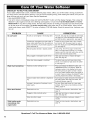
Faceplate Timer Features ......................................................................................................................... 22-25
How Your Water Softener Works .............................................................................................................. 26-28
Care of Your Water Softener ..................................................................................................................... 29-32
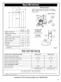
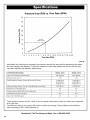
Specifications ............................................................................................................................................ 33-34
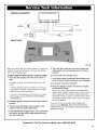
Service Tech Information ........................................................................................................................... 35-41
Exploded Views and Parts Lists ................................................................................................................ 42-47
Sears Tech Support ......................................................................................................................... Back Cover
Salt Hole Cover
Rating
Water Softener Model No.*
Serial Number
Date Installed
Water Hardness
Iron Content
pH
Water Pressure
Water Flow Rate
Decal
Grains Per Gallon
Parts Per Million
Taste and/or Odor
Pounds/Square Inch
Gallons Per Minute
* The model number is on the rating decal, located on the rim, under the salt hole cover.
Questions?
Call the Kenmore Water Line at 1-800-426-9345
or visit KenmoreWater.com
For repair or replacement parts, call toll-free 1-800-366-7278
See back cover for other Sears service numbers.
Questions? Call The Kenmore Water Line 1-800-426-9345

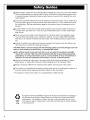
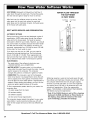
Read all steps, guides and rules carefully before installing and using your new water softener.
Follow all steps exactly to correctly install. Failure to follow them could cause personal injury
or property damage. Reading this book will also help you to get all of the benefits from your
water softener.
Your Kenmore Water Softener will remove hardness minerals from water. This is measured in
grains per gallon (gpg). It will also remove some clear water iron*. This is measured in parts
per million(ppm). See the specifications page for the maximum limits of hardness and iron
removal.
• A water softener will not improve other water problems such as acidity, tastes and odors, or
iron other than clear water iron. It will not purify contaminated water, or make unsafe water
safe to drink.
Check with your local public works department for plumbing, electric and sanitation codes.
You must follow their guides as you install your softener. Use only LEAD FREE SOLDER
AND FLUX, as required by federal and state codes, when installing soldered copper plumb-
ing.
Protect the softener and piping from freezing. Damage from freezing voids the softener war-
ranty. See how to protect from freezing on page 31.
CAUTION: Please read and comply with the following guides to prevent damage to the sof-
tener or other property, personal injury, or possible fatal shock.
This softener works on 24 volts only. Be sure to use only the transformer included.
Plug it into a nominal 120V, 60 cycle household outlet that is grounded and properly
protected by an overcurrent device such as a circuit breaker or fuse. If transformer is
replaced, use only the authorized service Class II, 24 volt, 10 VA transformer.
• Unplug the transformer right away if the power cable should become damaged or frayed.
Make repairs, or replace the transformer, before plugging back into the power outlet.
• Always unplug the softener from electrical power before removing outer valve covers.
• This system is not intended to be used for treating water that is microbiologically unsafe or of
unknown quality without adequate disinfection before or after the system.
* The capacity to reduce clear water iron is substantiated by WQA test data.
European Directive 2002/96/EC requires all electrical and electronic equipment to
be disposed of according to Waste Electrical and Electronic Equipment (WEEE)
requirements. This directive or similar laws are in place nationally and can vary
from region to region. Please refer to your state and local laws for proper disposal
of this equipment.
4

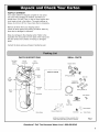
INSPECTSHIPMENT
Your water softener is shipped complete in one carton.
Use care when handling the softener. DO NOT turn
upside down. DO NOT drop, or set on sharp objects that
could make a hole in the bottom. The water softener is
heavy, do not try to lift it or move more than is necessary.
Remove all items from your shipping carton.
Check all items against the packing list below. Note any
items lost or damaged in shipment.
Note any damage to the shipping carton. Refer to the
exploded view and parts list in the back of the manual for
the part names and numbers of missing or damaged
items.
Contact the store where purchased if problems exist.
PARTS DESCRIPTIONS
Salt Hole Nozzle Valve
Cover Assembly Assembly
(Open)
SMALL PARTS
Bypass Valve
Salt
Storage
Tank
Face
',over
(Main)
Brinewell
Cover
Brinewell
Brine Valve
owner's manual
Ground Clamp Kit
O-Ring Seals (2)
Clips (2)
/d s_atlloa;(___ _,_k _
Drain Tubing Tube Clamp
Drain Clip
Drain Elbow
Tube Adaptor
Grommet _:;:#_ Tube Clamp
Additional Installation Fittings available from
Sears (see parts listing in back of manual)
FIG. 1
Questions? Call The Kenmore Water Line 1-800-426-9345

PLAN YOUR INSTALLATION
It is recommended to read through the entire manual before
beginning your installation. Follow all steps exactly. Reading this
manual will also help you get all the benefits from your system.
TOOLS NEEDED:
• Safety glasses
• Flathead screw driver
• Phillips screw driver
• Adjustable slip joint pliers
• Tape measure or ruler
J
Flathead Screwdriver
Safety Glasses Phillips Screwdriver Adjustable Slip Joint Pliers Tape Measure or Ruler
ADDITIONAL TOOLS NEEDED FOR THE FOLLOWING INSTALLATIONS:
SOLDERED COPPER
• Tubing Cutter
• Propane Torch
• Solid Core LEADFREE Solder
• Paste Flux
• Emery Cloth
or Sandpaper
THREADED PIPE
• Hacksaw or Pipe Cutter
• Pipe Wrenches
• Pipe Threading Tool
• Pipe Joint Compound approved
for use on potable water
CPVC OR PVC PLASTIC
• Hacksaw
• Adjustable Wrench
• Primer and Solvent Cement
approved for use on potable water-
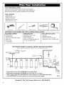
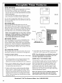
THE PROPER ORDER TO INSTALL WATER TREATING EQUIPMENT
(Shows sequence of equipment only. Seldom, if ever, would all items be needed.)
Kitchen or Bathroom
.... Cold Faucet
Sediment or Taste & |
I
Odor Cartridge Filter
Hard Water to
Outside Faucets
-- City Water Supply
OR
Cold, soft water I
_, WeIt Water Supply
I
I
Hot, soft water Solution I
Pressure or Dispensing I
Captive Air System
Tank
Sediment
Water Cartridge Filter
(Optional
Heater Location)
Water *Taste & Iron Neutralizer Clarifying
Softener Odor Filter Filter Filter
• Always place an Iron Filter UPSTREAM of the water softener.
• Always place a Neutralizer UPSTREAM of an Iron Filter, etc., as shown.
* Place a Taste & Odor Filter UPSTREAM of a water softener on a chlorinated water supply
and DOWNSTREAM of a water softener on a non-chlorinated water supply.
Welt Water
FIG. 2
Questions? Call The Kenmore Water Line 1-800-426-9345
6

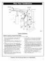
outside faucet
(hard water) - outside faucet
(hard water)
soft, cold _ _ toR.O, faucet
water ._,_ _ _ Hard _,_ ,_ ¢-- _-
SOwf_th I Shut-off [_- II toR ......
i . -Valve II
R.O.
wa!er I _____</' _II haid ...... // _ storage
nearer i I - ' Ihll water to // ../_'_--JF> tank
J I IIII1 house //
water /4 gap _
softener / . _
floor mare " •
drain
shutof
valve
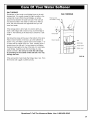
FIG. 3
Typical Installation
WHERE TO INSTALL THE WATER SOFTENER
Review the following points before you choose a place to put your softener.
1. Place as close as possible but always after, the
pressure tank (well water) or water meter (city
water). See Fig. 3.
2. Place as close as possible to a water drain such as
a floor drain, laundry tub, sump or standpipe. See
Fig. 3.
3. Connect to the house main water pipe BEFORE
THE WATER HEATER. See Fig. 3. Temperature of
water going through the softener must not be
more than 120°F (49°C). Hot water will damage
inner softener parts. To reduce the risk of hot water
backup, piping between the softener and water
heater should be as long of a run as possible.
4. Keep outside faucets on hard water to save soft
water and salt. See Fig. 3.
5. Do not install in a place where the softener could
freeze. Damage caused by freezing voids the war-
ranty by Sears, Roebuck and Co.
6. Put the softener in a place where water damage is
least likely to occur if it develops a leak. Sears or
the manufacturer will not repair or pay for water
damage.
7. A grounded, 120V electrical outlet is needed within
10 feet of the softener. See Fig. 3. This is to plug in
the transformer. The softener has a 10 foot power
cable. Be sure the outlet and transformer are in
an inside place, to protect from wet weather. Use
a continuously "live" outlet, which cannot be acci-
dentally switched off.
8. When installing in an outside location, you must take
the steps necessary to assure the softener, installa-
tion plumbing, and wiring, are protected from the
elements, contamination, vandalism, etc.
9. Keep the softener out of direct sunlight. The sun's
heat can melt plastic parts.
Questions? Call The Kenmore Water Line 1-800-426-9345

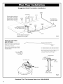
Suggested Slab Foundation Installation
water heater
kitchen
Plug the softener transformer
into an inside, 120 volt 60Hz
electrical outlet. If an outside
outlet is used, be sure it has
approved weather protection.
WATER SOFTENER
(install in garage, car port,
or other sheltered area)
bathroom
outside
-soft
€ " " bypass
" valve outside
-soft
Run drain tubing to laundry tub or
p-trap inside home, if possible.
Otherwise, run to a dry well.
outside
- hard
outside
- hard
water in
For outside hard
water, trench under-
ground as needed.
FIG. 4
DRAW IN YOUR PIPES
AND FITTINGS
Draw the plans for your "IN" and "OUT"
piping here. Include all pipe, fittings and
accessories you will use.
Make a list of all materials you will need
and buy them before you begin to install
the water softener.
120V - 60Hz
U
Electrical
Outlet
Left
Valve Outlet Side
Your House Main Water Pipe
Right
* In what direction does the water flow?
Be sure to plan "IN" and "OUT" piping so water
flow is to the softener valve inlet. Plan a
crossover if flow is from left to right.
CROSS-OVER
Main Water Pipe
Raw
Soft Water
Valve Inlet
Outlet Inlet
To Water Softener
FIG. 5
Questions? Call The Kenmore Water Line 1-800-426-9345
8

PIPE, FITTINGS, OTHER MATERIALS NEEDED
You must first decide how to run "in" and "out" pipes to
the softener. Look at your house main water pipe at the
point you will connect the softener. Is the pipe soldered
copper, glued plastic, or threaded galvanized or brass?
What is the pipe size? What kind of pipe and fittings is it
easiest for you to work with, and what tools do you have?
Now look at the common plans for "in" and "out" piping
on soldered copper. See Fig. 6. Use it as a guide to plan
what materials you will need. Get all the materials you
will need before you start.
Use Fig. 5 to make a plan drawing for your specific
installation. "In" and "out" fittings included with the soften-
er are 1" NPT threaded adaptors. You should maintain
the same, or larger, pipe size as the water supply pipe,
up to the softener inlet and outlet. Use copper, brass,
galvanized or PVC plastic pipe and fittings for the "in"
and "out" pipes. Be sure to check local codes.
Note: If converting from galvanized to copper pipe
use approved dielectric insulating connectors.
ALWAYS install the bypass valve (that is included with
the unit) or a three valve bypass. See Fig. 9 to13.
Bypass valves let you turn off water to the softener if
needed for repairs, but still have water in the house
pipes.
Drain tubing (3/8" inside diameter), is needed for the
valve and salt tank drains. See Fig. 16. If a rigid valve
drain is needed to comply with plumbing codes, you can
buy the parts needed (see Fig. 16) to change the soften-
er to a 1/2 inch minimum copper tubing drain.
OUT IN
Use teflon tape,
pipe
or both.
1" NPT sweat
adaptor (2)*
1" NPT
adaptor 2 of each
clip included
\
\
\
Bypass
Valve
"Valve
4
Toconnect to 1-1/4"
, copper household ,
' plumbing '
\
1" NPT sweat OUT
adaptor (2)*
Use teflon tape,
pipe joint compound
or both.
_ _..................\\
/ \
Toconnect to 1-1/4")
copper household j'
_. plumbing /
IN
clip
1" NPT
X adaptor
Valve
Inlet
2 of each
included
FIG. 6
*NOTE:
For plumbing connection, buy 2 sweat adaptors and plumb
directly to the inlet - outlet adaptors. Threads on the inlet - outlet
adaptors are 1" NPT.
CAUTION:
DO ALL SOLDERING BEFORE CONNECTING SWEAT ADAP-
TORS TO INLET-OUTLET ADAPTORS OR BYPASS VALVE.
Questions? Call The Kenmore Water Line 1-800-426-9345

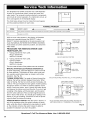
BEFORE INSTALLING CHECKS & TESTS
Your water supply needs to be checked for chemical
analysis, water pressure and water flow rate. To accom-
plish this, complete the following steps:
Check Water's Chemical Analysis: Sears sells a com-
plete line of water treating equipment to correct various
water problems. To be sure you have the proper type
and size equipment, You must have your water tested.
Your Sears store can give you a water test results for
hardness, iron and acidity, and tell you what equipment
you need. Simply take at least a 4 oz. sample of your
water to Sears, and they will test it while you wait. If you
need help to get your water tested, or if you have other
questions about your water, ask at your Sears store.
NOTE: Add these readings to the Facts and Figure
table on page 3.
Check Your Water Pressure: For your softener to work
right, a water pressure of no lower than 20 pounds per
square inch (psi) is needed in the house water pipes.
The highest pressure allowed in the water pipes is 125
psi. If pressure is over 125 psi, buy and install a pres-
sure reducing valve in the water inlet pipe to the soften-
er.
NOTE: If water pressure during the day is 100 psi or
more, pressure during the night may go over 125 psL
Adding a pressure reducing valve may reduce the
flow.
NOTE: Add these readings to the Facts and Figure
table on page 3.
If you have a well water system, look at the pressure
gauge to find the water pressure. Call your local water
department if you have city water. They will tell you what
the water pressure is where you live.
NOTE: Add these readings to the Facts and Figure
table on page 3.
Check your water flow rate: A water flow of at least 3
gallons per minute is needed. A lower flow will keep your
softener from working as well as it should. Complete the
following steps to make an easy check of your flow rate.
1. Fully open two cold water faucets close to the point
water enters the house.
2. With both faucets open, fill a gallon container at one
faucet while looking at a watch or clock to see how
many seconds it takes.
3. Empty the container and go to the second faucet (be
sure BOTH faucets are still on). Fillthe gallon container
at the second faucet and see how many seconds it
takes.
4. Turn off both faucets. Now add the number of seconds
it took to fill the container at both faucets.
5. A total of 90 seconds, or less, means the system flow
rate is good.
NOTE: Add these readings to the Facts and Figure
table on page 3.
NOTE: Codes in the state of Massachusetts require
installation by a licensed plumber. For installation,
use plumbing code 248CMR of the Commonwealth
of Massachusetts.
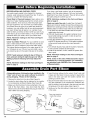
A disposable piece of tubing has been installed in the
"drain" port of your new water softener to protect it
during shipping. Please do the following:
1. Remove the tube from the valve (See Figure A).
2. Locate the drain elbow that is attached to the installa-
tion accessories cardboard display (See Figure B).
3. Make sure that the black O-ring is attached to the out-
side of the drain elbow. Also look inside the drain
elbow to be sure the small black flow plug is inside and
hasn't fallen out during shipping.
4. Insert the drain elbow into the valve's "drain" port until
it stops and the black O-ring is pushed in beyond the
slots in the drain port with the smaller, barbed end
pointing out of the valve.
5. Secure the drain elbow to the valve using the black "U"
clip (also attached to the accessories cardboard dis-
play) by sliding it into the slots in the drain port and into
the grooves in the drain elbow (See Figure C).
6. Gently pull on the drain elbow to make sure it is secure
in the valve.
Rt:bTe Ctip_ _
FIG. A
Flow plug (should be
inside drain elbow'
O-ring
_'_-..... Drain
elbow
Drain port
FIG. B FIG. C
10

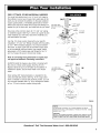
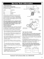
ASSEMBLE INLET OUTLET ADAPTORS,
OR SINGLE BYPASS VALVE
Complete the following steps to assemble the adaptors or
bypass valve.
1. Close the shutoff valve on the house main water pipe,
near the water meter or pressure tank, to turn off the
water. See Fig. 7.
2. Shut off the gas or electric supply to the water heater.
See Fig. 7.
3. Open the highest and lowest water faucets in your
house. This will let water drain from the pipes. Close
faucets after water has drained.
4. Remove the main cover. See Fig. 8.
Pull outward on two (2) tabs to release.
The salt hole cover remains attached to the main cover
when removed. Set both covers aside so they will not get
scratched or broken.
Shutoff Shutoff . Pressure
Valve
Valve L/Tank
Pump
Electrical
Panel
FIG. 7
Salt Hole Cover
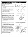
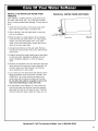
INSTALL SEARS BYPASS VALVE AND / OR THE
INLET OUTLET THREADED ADAPTORS
NOTE: If you will not install the bypass valve because
you will have a three (3) valve bypass, skip steps 6 &
7, but do steps 5 and 8.
5. Visually check and remove any foreign materials from
the valve inlet and outlet ports. See Fig. 9. Carefully
remove the two large plastic clips (you will use them).
Check to be sure the turbine and turbine support are
firmly in place. See Fig. 10.
FIG. 8
BYPASS VALVE:
6. Put a light coating of silicone grease on the o-ring seals
and slide onto the bypass valve.
7. Push the bypass valve into the softener valve as far as it
will go. Snap the two large holding clips into place,
from the top down as shown. See Fig. 11.
CAUTION: Be sure the clips snap firmly into place so
the bypass valve will not pull out. See Fig. 11.
INSTALLING BYPASS VALVE, AND/OR
INLET AND OUTLET THREADED ADAPTORS
Clip (2)
Valve Outlet
INLET AND OUTLET THREADED ADAPTORS:
8. Put a light coating of silicone grease on the o-ring seals
and slide into the threaded adaptors. Push the adaptors
into the valve inlet and outlet ports, or bypass valve
ports, as far as they will go. Both adaptors are the same
and fit either port. Snap the two large holding clips
into place, as shown. See Fig. 11.
CAUTION: Be sure the clips snap firmly into place so
the tubes will not pull out. See Fig. 11.
Valve Inlet_ _.
Included with
Softener
Included with
Softener
FIG. 9
Questions? Call The Kenmore Water Line 1-800-426-9345
11

Before installing the bypass valve, or
copper tube, be sure the turbine and
support are firmly in place in the
valve outlet port.
Turbine
Support Sensor Port
Turbine
FIG. 10
Bypass Valve or
Installation Adaptor
INSTALLING HOLDING CLIPS
Black Clip Cross Section of Valve
Inlet or Outlet
O-Ring
Clip Snaps into Place
Between Larger Diameter Rings FIG. 11
BYPASS VALVE TURNED DOWNWARD
Turn bypass valve upside
down to connect to floor
level plumbing.
FIG. 12
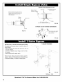
INSTALLING 3 VALVE BYPASS AND PIPES
Complete the following steps to install the three (3)
valve bypass:
• Cut the house main water pipe where you will con-
nect the softener.
• Loosely put together pipe, fittings, and the three
(3) valves.
• Place valve(s) within easy reach.
When all pipe, fittings and valves make a good fit
together, tighten all threaded joints (use pipe dope
on outside threads), or solder all sweat joints.
3 VALVE BYPASS
TO FIG. 13
Softener Inlet
Questions? Call The Kenmore Water Line 1-800-426-9345
12

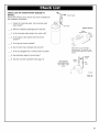
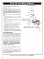
POSITION SOFTENER INTO PLACE
Complete the following steps to position the softener.
1. Grip under the ridge on the salt tank sidewall.
2. Carefully rock back and forth into position.
3. Move the softener into position.
4. Place on a level and smooth surface. If needed, put a
piece of 3/4" plywood, at least 17" x 20", under the
tank. Then put spacers under the plywood to level the
softener. See Fig. 14.
NOTE: Do not put shims or spacers directly under
the tank, without the plywood. The weight of the sof-
tener, when full of salt and water, may cause the tank
to puncture or break at the shim or spacer.
CONNECT THE SOFTENER
Refer to your plan drawing. See Fig. 5.
Measure, cut (thread if needed) and put all pipe and fit-
tings together up to the main water pipe, or to the
bypass valve(s) you installed in the previous step.
CAUTION: Never solder fittings while connected to
nonmetalfic parts. Wait until soldered pipe has
cooled before connection. See Fig. 15.
CAUTION: Be careful when putting pipe fittings
together. Do not cross thread, and do not overtight-
en.
4. Solder
MOVE SOFTENER INTO PLACE
Grip under ridge
to move softener.
Plywo_
II
::::1__
Shims
FIG. 14
TYPICAL SOLDERING
CONNECTIONS
Main Water Pipe
NOTE: To be certain heat will
not travel down the pipe and
into the bypass valve (or
installation adaptors), wrap
the bottom of the pipe and the
bypass valve in a wet rag.
I
i
Hard Water
1. Cut pipe to
correct length.
2. Solder (WHEN
COOL, do Step 3).
3. Put threaded adaptor
into bypass valve
port.
FIG. 15
Questions? Call The Kenmore Water Line 1-800-426-9345
13

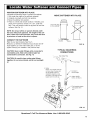
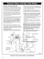
CONNECT THE VALVE DRAIN HOSE
Take a length of 3/8" inside diameter drain tubing and
attach one end to the drain fitting. See Fig. 16. Use a
tube clamp to hold it in place. Put the other end of the
tubing over a floor drain, into a laundry tub, standpipe,
or other suitable drain. Check your local codes.
Leave an air gap of about 1-1/2" between the end of
the hose and the drain. This gap is needed so you
don't get a backflow of sewer water into the softener.
Do not put the end of the hose into the drain or con-
nect without the air gap.
Place and support the hose so it does not kink or have
sharp bends. Secure the hose end so water pressure
does not cause the hose to "whip". Tie or wire it in
place. Do not pinch the hose shut. The softener will
not work if this drain hose is pinched, plugged,
closed or restricted in any way. Direct drain flow
down into drain from drain line as flow could possibly
over shoot the drain cover.
Keep the hose lower than the drain fitting. In some
homes, to get to a drain you must raise the hose and
run it overhead. If you need an overhead drain, do not
raise the hose more than 8' above the floor. A copper
drain tube is best to use.
COPPER DRAIN TUBE: The local plumbing codes
may require the use a copper valve drain tube. A cop-
per tube is also best to use for an overhead drain. Use
a copper drain tube if the softener is installed outside,
or in the sunlight. Heat from the sun can soften, flatten
and close up some kinds of tubes.
To adapt a copper drain tube to the softener, buy a
compression fitting (1/4" female pipe threads x 1/2"
O.D. tube) and tubing from your local hardware store.
CONNECT SALT TANK OVERFLOW TUBING
1. Locate the rubber grommet, tube adaptor and tube
clamp (see Fig. 16) that are in the parts bag.
2. Push the grommet into the hole in the salt tank wall
so half is inside and half is outside.
3. Push the bigger end of the tube adaptor into the
grommet.
4. Push one end of a length of 3/8" I.D. tubing onto
the tube adaptor, using the tube clamp to hold it in
place.
5. Put the other end of the tubing over the floor drain.
IMPORTANT: Overflow water must run downward
through the tubing. Do not raise the tubing higher
than the grommet and tube adaptor. See Fig. 16.
IMPORTANT: Do not connect to the valve drain
hose you installed in step 1. Both drains must
have a separate hose or tube.
NOTE: Overflow drain tubing is available from
Sears. See parts list in back of manual.
Drain
Fitting
Tube _,
Clamp
NOTE: Overflow
drain tubing is avail-
able from Sears,
Item No. 42-3433
(20 ft).
Overflow Drain Tubing I_
\\
\\
\\
• 1/4 NPT Threads
Chp,,__ _ Comp Fitting. 1/4 NPT x 1/2 in.
\ ! Barbs O.D. Tube (Not furnished)
Drain Fitting (Pull 1/2" Outside Diameter
clip and remove Copper Tube (Not furnished)
fitting from valve.)
\\
To drain
\_\ point other ..... STANDPIPE_
than floor "_,
\k
\\
_" drain. '_ iit.
Valve Drain __--,_ n---r
Support
H--
Hose
tubing in II !-1/2''
place as I _ Air Gap
Tie or Wire 1-1/2" needed. J
Tubing in Air Gap
Place
FLOOR DRAIN
-=-==_,, 1-1/2" Air Gap
LAUNDRY TUB
FIG. 16
Questions? Call The Kenmore Water Line 1-800-426-9345
14

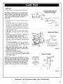
LEAK TEST
To check for leaks, complete the following steps:
CAUTION: To avoid water or air pressure dam-
age to softener inner parts, and to flush pipe
chips or other residue from the water pipes, be
sure to do the following steps exactly as
instructed.
1. Fully open two cold, soft water faucets near the
softener.
2. Look at the pictures in Fig. 18 and 19 to deter-
mine your kind of bypass valve(s). Place bypass
valve(s) in "bypass" position. On a single valve,
slide the stem inward to bypass. On a three (3)
valve system, close the inlet and outlet valves and
open the bypass valve.
3. Fully open the house main water pipe shutoff
valve. Observe steady water flow from both open
faucets.
4. Place bypass valve(s) in SERVICE EXACTLY as
follows: Keep soft water faucets open.
a. Single Bypass Valve: Slowly, slide pull the
valve stem outward toward service, pausing sev-
eral times to allow the softener to pressurize slow-
ly.
b. Three Valve Bypass: Fully close the bypass
valve and open the outlet valve. Slowly, open the
inlet valve, pausing several times to allow the sof-
tener to pressurize slowly.
5. After about three minutes, open a hot water
faucet for about one minute, or until all air is
expelled, then close.
6. Close both cold water faucets.
7. Check your plumbing work for leaks and fix right
away if any are found. Be sure to observe previ-
ous caution notes.
NOTE: If this procedure is performed on a new
softener, water coming from the taps may initial-
ly be discolored. This normally occurs the first
time water runs through the resin bed. The dis-
colored water is not harmful, and the discol-
oration will not last more than a few minutes.
HOUSE MAIN WATER
SHUTOFF VALVES
Shu_
Water ¢--_:h _ Pressure Tank
Meter Shutoff Valve_ / "1"-
Well Pump
FIG. 17
SINGLE BYPASS
Pull Stem Outward
For Service
_Push Inward
For Bypass
Note: Stem may be installed
in either direction. The end
with writing should be pulled
out for service position.
FIG. 18
FOR SERVICE
Close bypass valve.
Open inlet & outlet
valves.
FOR BYPASS
Open bypass valve.
Close inlet & outlet
valves.
VALVE BYPASS
Bypass
Outlet i " Valve
Valve Inlet
Valve
FIG. 19
Questions? Call The Kenmore Water Line 1-800-426-9345
15

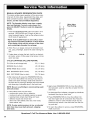
INSTALLGROUNDINGCLAMPBETWEEN
THESOFTENERINAND OUT PIPES
The house cold water pipe (iron or copper) is often
used to ground all electrical outlets in the home.
Outlets are grounded to protect you from shock when
you touch any electric appliance plugged into the out-
let. If you installed the single bypass valve, the cold
water pipe ground is broken. See Fig. 20 and 21.
IMPORTANT: Be sure the cold water pipe has
direct metal to metal contact all the way to the
ground. Plastic, rubber or other electrically insulat-
ing parts such as hoses, fittings, washers or gas-
kets can break the direct metal to metal contact.
Also check the water meter (city water) or the well
pump. Install #4 copper jumper wires, clamped
tightly on both ends, across insulated parts. See
Fig. 21.
To restore the ground, take the ground clamp kit that is
in the parts bag. Install across the inlet and outlet cop-
per tubes. See Fig. 20. Be sure good contact is made
between the pipe and the clamps.
ELECTRICAL POWER OUTLET FOR
YOUR SOFTENER
The softener works on 24 volt, 60 Hz electric power.
The included transformer changes standard 120 volt
AC house power to 24 volts. You must plug the trans-
former into a grounded, 120 volt outlet only. Be sure
the outlet is always "live" so someone cannot turn it off
by mistake. See Fig. 22.
NOTE: The included transformer is made for inside
use only. Be sure the electrical outlet you plug the
transformer into is inside, to protect from weather.
PLUG IN THE TRANSFORMER
Plug the transformer into the electrical outlet.
COLD WATER PIPE GROUNDING
Ground
Clamp (2%
Screw with lock j
washer and nut
TO
Valve Inlet
FROM
Valve Outlet
FIG. 20
WATER METER JUMPER WIRE
#4 Groundwire
FIG. 21
CONNECTING TRANSFORMER
Transformer
Power Cable
120V-60Hz
Electrical
Outlet
._p--- From Face Plate-Timer
FIG. 22
Questions? Call The Kenmore Water Line 1-800-426-9345
16

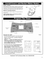
INSTALLCOVERS
After installing your water softener, replace the covers. Angle
the covers so the main cover clips onto the back first, then
bring down in front and clip on the two (2) tabs inside the rim
of the salt hole and lower the salt cover closed. See Fig. 23.
RESTART THE WATER HEATER
Turn on the gas (or electric) supply to the water heater and
light the pilot.
YOUR PLUMBING INSTALLATION AND ELECTRICAL
WORK ARE NOW COMPLETE.
Cover
(Main)
Salt Hole
Cover
FIG. 23
Salt Level Adjust Display
REGENERATION Button
UP Button
Signal Light
Adjust
DOWN Button
Tank Light
PROGRAM THE TIMER
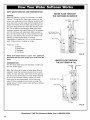
1. When the transformer is plugged in, the model code H 32,
and a test number (example: J1.1) show in the face plate
display for 4 seconds. Then, 12:00 AM and PRESENT
TIME begin to flash.
NOTE: If '; - - -" shows in the display, press the UP or
DOWN button until either H 32, for model 38376, or
H 33, for model 39376, shows in the display. Then,
press the SELECT button to set, and change to the
flashing PRESENT TIME display.
2. To check the model code, unplug the transformer at the
wall outlet and plug in again. If other than this code
shows, refer to the Troubleshooting Section.
SOUND "BEEPER": A "beeper" sounds while pressing
buttons for timer setup. One beep signals a change in the
face plate display. Repeated beeps mean the timer will not
accept a change from the button you have pressed, telling
you to use another button. For example, while setting the
hardness the beeper sounds repeatedly when the display
reaches 1 using the DOWN button, or the highest hard-
ness setting using the UP button.
SELECT Buttons
_ i_ I I -I -I
17 _-IC
I I I
_____ J J,J
_ i_ I I 7 -I
17 _7-I
I I I
_____ J J,J
FIG. 24
- -8- - IC,I_IU
PRESENT TIME
_ __ _
- -8- -
_ ___ _
i 7,1717 AM
IC ,I_IU
PRESENT TIME
FIG. 25
Questions? Call The Kenmore Water Line 1-800-426-9345
17

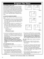
SET PRESENT TIME OF DAY
Ifthe words PRESENT TIME do not show in the display,
press the SELECT1 button until they do show in the dis-
play. Press the UP or DOWN buttons to set the present
time. Press UP to move the display ahead; press DOWN
to move the time backward. If the present time is between
noon and midnight, be sure PM shows. If the present time
is between midnight and noon, be sure AM shows. Each
press of the UP or DOWN buttons changes the time by
one (1) minute. Holding the buttons in changes the time
rapidly.
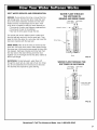
SET WATER HARDNESS NUMBER
To set the water hardness number, complete the following
steps:
1. Press the SELECT1 button once to display 25 (flashing)
and HARDNESS. The grains per gallon (gpg) hardness
of your water supply is on your water analysis report. Be
sure to enter water test results on the Facts & Figure
Chart on page 3.
2. If your water supply contains iron, compensate for it by
adding to the water hardness number. For example,
assume your water is 20 gpg hard and contains 2 ppm
iron. Add 5 to the hardness number for each I ppm of
iron. In this example, you would use 30 for your hard-
ness number.
2ppmironx5= 10
20 gpg hardness
+10
30 HARDNESS NUMBER
11
ILl, 70
PRESENT TIME
I ,-,,-,
8
HARDNESS
_ ___ _
8 I- ,LII_I
RECHARGE
TIME
U,I-I I-I PM
I'UU
PRESENT TIME
FIG. 26
FIG. 27
FIG. 28
[_ _;_ OF
i ,-,, ,,_ I
I I-
I-<L I
FIG. 29
,
Press the UP or DOWN buttons to set your water hard-
ness number in the display. The DOWN button moves
the display to 1. The UP button moves the display to the
highest setting (see maximum setting for your model in
the specifications).
NOTE: Each press of the UP or DOWN button
changes the display by 1 between 1 and 25.
Between 25 and the highest number, the display
changes 5 at a time (25, 30, 35, etc.) Holding the UP
or DOWN button in changes the display twice each
second.
SET REGENERATION TIME
To complete setting the regeneration time, complete the
following steps:
1. Press the SELECT1 button to display 2:00 AM (flashing)
and RECHARGE TIME.
,
At the 2:00 AM recharge time setting, the softener
begins regeneration (see pages 26 - 28) at 2:00 AM.
This is a good time in most households because water
is not being used. If a different recharge time setting
would be better for your household, complete the follow-
ing step.
3. Press the UP or DOWN buttons to set the desired
recharge starting hour. Be sure to observe the AM-
PM as you did when setting the present time of day.
Note: Each press of the UP or DOWN buttons
changes the display one hour. Holding the but-
tons in changes the display twice each second.
SET SALT TYPE (sodium chloride or potassium
chloride)
To set the salt type, complete the following steps:
1. Press the SELECT 1 button to display nACI, the
default setting.
,
If you want to use potassium chloride (KCl) instead
of standard sodium chloride (NaCl) water softener
salt, be sure to set KCl in the display by using the
UP button. The KCl setting adjusts regeneration
cycle times to compensate for the variable dissolving
rate of potassium chloride. Refer to page 20 for infor-
mation on various salts.
3. Press the SELECT button once again, to complete
initial programming, and the current time of day
shows in the display.
Questions? Call The Kenmore Water Line 1-800-426-9345
18

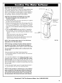
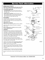
SANITIZE THE WATER SOFTENER
Care is taken at the factory to keep your water softener clean
and sanitary. Materials used to make the softener will not
infect or contaminate your water supply, or cause bacteria to
form or grow. However, during shipping, storage, installing
and operating, bacteria could get into the softener.
SANITIZE YOUR WATER SOFTENER AS FOLLOWS:
1. Be certain the bypass valve is pulled out to
"service" position.
2. Liftthe salt hole cover and using a pail add up to 3 gallons
of water to the salt storage tank.
3. Remove the brine well cover (Fig. 30) and pour about 3/4
ounce, or 1 to 2 tablespoons, of common 5.25% 1,unscent-
ed, household bleach (Clorox, Linco, BoPeep, White Sail,
Eagle, etc.) in the softener brinewell. Replace the brinewell
cover.
4. Press the RECHARGE button and hold for 3 seconds to
start a recharge. This first recharge does several things.
• It draws the bleach into and through the softener to sani-
tize it.
• It fills the salt tank to the water level needed.
• It gets all the air out of the resin tank.
• It prepares the resin bed (see page 26) for service and
flushes residual chlorine from the softener.
NOTE: This recharge takes about 2-1/2 to 2-3/4 hours,
depending on the salt type setting.
NOTE: During a recharge the water softener bypasses
raw water to the home. You will not get salty water or
affect the regeneration cycle if water is used at this time.
You can sanitize the softener with or without salt in the
storage tank.
1Recommended by the Water Quality Association.
On some water supplies, the water softener may need peri-
odic disinfecting.
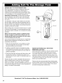
Your new Sears softener is now softening the water for your
household needs. However, your WATER HEATER is filled
with hard water. To have fully soft water right away, you can
drain the water heater so it refills with soft water. If you don't
drain the water heater, it will take a few days before you have
fully soft water.
To drain the water heater, open a hot water faucet and let it
run until the water runs cold. Then close the faucet.
NOTE: If this procedure is performed on a new softener,
water coming from the taps may initially be discolored.
This normally occurs the first time water runs through
the resin bed. The discolored water is not harmful, and
the discoloration will not last more than a few minutes.
Water
About 3 gallons
Salt Hole
Brinewell Cover
_ / /(Removeand
add about
...... :_ 3/4 oz. bleach)
Brinewell
FIG. 30
Questions? Call The Kenmore Water Line 1-800-426-9345
19

ADDINGSALTTOTHESTORAGETANK
Brine(saltdissolvedinwater)isneededforeachand
everyregeneration.Thewaterformakingbrineis
meteredintothesaltstoragetankbythesoftener.You
mustkeepsaltinthetank,butbecausethewatersoften-
erisveryefficient,itisnotnecessarytokeepitfull.
Especiallyin humidareas,itisbesttofillthestorage
tankonequartertoonehalffull,andtoaddsaltmore
often.Saltbridgingoccursmoreoftenwhenconditions
arehumid.
UseNUGGETorPELLETwatersoftenersalt.DONOT
userocksalts,astheyhavedirtandsedimentsthatwill
stopthesoftenerfromworking.Tomaintainoptimumper-
formanceofyourwatersoftener,thesalttankshouldbe
cleanedoutevery2to3years.
Beforeaddingsalt,besurethebrinewellcoverisinplace
onthetopofthebrinewell.Itisrecommendedtosetthe
saltmonitorsystem,althoughitisnotrequiredforproper
operation.
NOTE: The salt monitor system is calibrated to the
density of nugget or pellet water softener sail The
monitor will not work as accurately with other types
of salt including rock and solar.
If you choose Potassium Chloride (KCl) as a regenerant,
following these suggestions will help give you years of
maintenance free service.
,
,
,
Place only one bag of KCl in your softener at a time
(the salt storage tank should contain no more than
60 pounds of KCl at any one time).
A softener using KCl should not be placed in areas
with temperature fluctuations and high humidity (KCl
will harden in these environments and may make the
softener inoperable).
Check the brine tank and brine well (black tube in salt
storage tank) monthly. If hardening is present, pour
small amounts of warm water on hardened areas until
they loosen.
Persons who are on sodium restricted diets should con-
sider the added sodium as part of their overall sodium
intake. For example, if your water supply is 15 grains
hard, and you drank 3 quarts of softened water you would
consume 335 milligrams of sodium. That is equivalent to
eating 2-1/2 slices of white bread.
Salt
Storage'_
Tank
Brinewell
FIG. 31
WATER SOFTENING SALT WITH IRON
REMOVING ADDITIVES
Some salts have an additive to help the softener handle
iron in the water supply. These salts may be used if
your water supply has a high iron content. It is recom-
mended to use Sears Resin Bed Cleaner (refer to the
Parts List in back of manual for part number) for period-
ic treatments to keep your resin bed clean. This is avail-
able at your local Sears store.
Persons who are concerned about their drinking water
should consider a Kenmore Drinking Water System that
will remove or reduce in excess of 90% of the sodium
and other drinking water contaminants.
Questions? Call The Kenmore Water Line 1-800-426-9345
20
Page is loading ...
Page is loading ...
Page is loading ...
Page is loading ...
Page is loading ...
Page is loading ...
Page is loading ...
Page is loading ...
Page is loading ...
Page is loading ...
Page is loading ...
Page is loading ...
Page is loading ...
Page is loading ...
Page is loading ...
Page is loading ...
Page is loading ...
Page is loading ...
Page is loading ...
Page is loading ...
Page is loading ...
Page is loading ...
Page is loading ...
Page is loading ...
Page is loading ...
Page is loading ...
Page is loading ...
Page is loading ...
-
 1
1
-
 2
2
-
 3
3
-
 4
4
-
 5
5
-
 6
6
-
 7
7
-
 8
8
-
 9
9
-
 10
10
-
 11
11
-
 12
12
-
 13
13
-
 14
14
-
 15
15
-
 16
16
-
 17
17
-
 18
18
-
 19
19
-
 20
20
-
 21
21
-
 22
22
-
 23
23
-
 24
24
-
 25
25
-
 26
26
-
 27
27
-
 28
28
-
 29
29
-
 30
30
-
 31
31
-
 32
32
-
 33
33
-
 34
34
-
 35
35
-
 36
36
-
 37
37
-
 38
38
-
 39
39
-
 40
40
-
 41
41
-
 42
42
-
 43
43
-
 44
44
-
 45
45
-
 46
46
-
 47
47
-
 48
48


Kenmore 625393760 User manual
- Category
- Water dispensers
- Type
- User manual
Ask a question and I''ll find the answer in the document
Finding information in a document is now easier with AI
Related papers
-
Kenmore IntelliSoft 370 Series Owner's manual
-
Kenmore IntelliSoft 370 Series Owner's manual
-
-
-
-
-
-
-
-
Other documents
-
 tankRo RO132-TNK User manual
-
 Express Water RO132-TNK User manual
-
 tankRo RO132-TNK Installation guide
-
GE GXSF23Z01 User manual
-
Ralph Lauren RL 1320 Installation guide
-
-
GE GXSF30V User guide
-
GE SMARTWATER GXSF27B User manual
-
 Express Water GTS11 User manual
-
GE GNSF35Z01 User manual


