
UK-Kit-3S
Model UK-KIT-3S for
22′ refrigerators with the freezer
on the bottom.
Safety Information . . . . . . . . . . 2
Operating Instructions
How The Icemaker Works . . . . .3
How To Use Your Icemaker . . . .3
Troubleshooting Tips
Before You Call For Service . .4, 5
Installation Instructions
Before You Begin . . . . . . . . . .6, 7
Installing The Icemaker . . . . .8, 9
Water Line Installation . . .11–13
Water Valve Installation . . . . . .10
Consumer Support
Consumer Support . .Back Cover
Warranty . . . . . . . . . . . . . . . . . . .15
Icemaker Accessory Kit
www.GEAppliances.com
UK-KIT-3S
10527055 162D1599P009 49-60130 05-01 JR
Owner’s Manual and
Installation Instructions

READ AND FOLLOW THIS SAFETY INFORMATION CAREFULLY.
READ AND SAVE THESE INSTRUCTIONS
SAFETY PRECAUTIONS
IMPORTANT SAFETY INFORMATION.
READ ALL INSTRUCTIONS BEFORE USING.
For Your Safety:
Do not place fingers or hands in the automatic
icemaking mechanism while the refrigerator is
plugged in. This will help protect you from
possible injury.
It will also prevent interference with moving parts
of the ejector mechanism and the heating element
that releases the cubes, located on the bottom of
the icemaker.
2

About the automatic icemaker.
www.GEAppliances.com
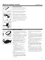
How the Icemaker Works
Water fills the empty cube mold when the
freezer has cooled to freezing temperature.
Cold air is forced directly over mold.
When frozen, the cubes are moved up and
out of the mold. The sweeper arm ejects
them into the ice storage bin below.
The feeler arm senses when the bin is full
and signals the icemaker to stop ejecting
more cubes. However, the mold has been
refilled and cubes frozen so the new supply is
ready when needed. As soon as ice is
removed from the bin, the feeler arm signals
that more is needed. Icemaker resumes
operation by ejecting ready-and-waiting
frozen cubes.
Ice
Sweeper arm
Ice storage bin
Feeler arm
Ice
storage
bin
How to Use Your Icemaker
■To start the Icemaker, lower the feeler arm to
the ON (down) position. Make sure the ice
storage bin is below the icemaker and pushed
back as far as possible.
■When the Icemaker is first connected or after
any extended period of non-use, you should
discard the first few batches of cubes. Use ice
regularly to maintain the best quality.
■The feeler arm must be free to operate
upward and outward over the top of the ice
storage bin during each ice-delivery cycle.
Make sure packages in the freezer
compartment do not block its movement.
■Raise the feeler arm to the STOP (up)
position when:
• Ice storage bin is to be removed for
extended period of time.
• Refrigerator is not to be used for an
extended time, such as vacations.
Also, turn off the water supply to the
icemaker in this instance.
• Water supply is to be shut off for several
hours.
■During operation, you may hear certain
sounds, such as the hum of the motor,
movement of the cube ejector, humming
or clicking of the water valve, and rattling
of ice as it falls into the bin. These sounds
are normal.
■The Icemaker ejects cubes in groups and
it is normal for several cubes to be joined
together.
■Ice cubes that have been in the ice storage bin
for a considerable length of time may pick up
off-flavor tastes, stick together and gradually
become smaller. We suggest that these cubes
be thrown away.
■You may, on occasion, find a few smaller than
normal cubes in the bin. This is probably
caused by low water pressure at time of water
fill, and is no cause for concern.
■The ice storage bin should be cleaned
occasionally in warm water. Rinse and wipe
dry. Be sure to put the icemaker feeler arm
in the STOP (up) position when cleaning
the bin.
■Keep the ice level to keep it coming. If the
cubes should build up in one area of the
ice storage bin after being ejected from the
mold, just level them out with your hand.
Keep the cubes distributed evenly and the
bin can reach its maximum cube capacity.
3
Arm down–
icemaker
will operate
Arm up–
stops operation

Before you call for service…
Troubleshooting Tips
Save time and money! Review the charts on the following
pages first and you may not need to call for service.
4
Problem Possible Causes What To Do
Automatic icemaker
Feeler arm is in the • Set the icemaker feeler arm to the
ON
(down) position.
does not operate STOP
(up) position.
Electrical power cord may • Make sure plug from power cord fits tightly into wall outlet.
not be plugged in.
Icemaker is not getting the • Make sure the water supply is connected and turned on.
necessary supply of water. Check for kinks in the 1/4″water supply tubing. Remove
kinks or replace tubing if there are kinks.
Freezer compartment too warm. • Turn the temperature control to a cooler setting. See the
controls section in your refrigerator’s Owner’s Manual.
Cubes are too small
Shutoff valve connecting the • Unclog it.
refrigerator to the home water
line may be clogged.
Ice cubes have
Ice stored for an extended • Use ice regularly. Discard old cubes.
odor/taste
period may absorb odors,
which affect their taste.
Ice storage bin needs to be • Empty and wash ice storage bin.
emptied and washed.
Food transmitting odors/taste •Wrap foods well.
to ice cubes.
Interior of the refrigerator •See your refrigerator’s Owner’s Manual.
needs cleaning.
Icemaker is not
Water pressure is too low. • Low water pressure can cause valve to leak. Water pressure
producing ice
must be between 20 and 100 psi to function properly.
A minimum pressure of 35 psi is recommended for units
with water filters.
Improper water valve • Check water connection procedure in these Installation
installation. Instructions. Self-piercing and 3/16″saddle valves cause
low water pressure and may clog the line over time.
Icemaker wiring harness • Check icemaker wiring harness connection.
is not completely inserted
in outlet.
Freezer section not operating • Confirm that freezer section is operating at proper
at proper temperature. temperature. See the controls section in your refrigerator’s
Owner’s Manual.
Icemaker is not
Icemaker has just recently • Wait 24 hours for ice production to begin and for ice to
producing enough ice
been installed or a large amount restock after being emptied.
or ice is deformed
of ice has just been used.
Water pressure is too low. • Check house water pressure. Water pressure must be
between 20 and 100 psi to function properly. A minimum
pressure of 35 psi is recommended for units with water filters.

www.GEAppliances.com
Problem Possible Causes What To Do
Ice cubes stick together
Ice not being used often enough. • Empty ice cube bucket more frequently.
or “shrink”
Ice forms in inlet tube
Water pressure is too low. • Low water pressure can cause valve to leak. Water pressure
to icemaker
must be between 20 and 100 psi to function properly.
(on some models)
A minimum pressure of 35 psi is recommended for units
with water filters.
Freezer compartment is • Turn the temperature control to a cooler setting. See the
too warm. controls section in your refrigerator’s Owner’s Manual.
Unit is leaking water
Unapproved plastic tubing • Use only copper tubing or plastic tubing from a GE
was used to complete water SmartConnect™ Refrigerator Tubing Kit. The only GE
connection. approved plastic tubing is that supplied in GE SmartConnect™
Refrigerator Tubing Kits. Do not use any other plastic water
supply line because the line is under pressure at all times.
Other types of plastic will crack or rupture with age and cause
water damage to your home. GE is not responsible for property
damage due to improper installation of water connection.
Water pressure is too low. • Check house water pressure. Water pressure must be between
20 and 100 psi to function properly. A minimum pressure of
35 psi is recommended for units with water filters.
Improper water valve installation. • Check water connection procedure in these Installation
Instructions. Self-piercing and saddle valves cause
low water pressure and may clog the line over time.
5

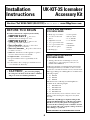
BEFORE YOU BEGIN
Installation UK-KIT-3S Icemaker
Instructions Accessory Kit
Read these instructions completely and carefully.
•
IMPORTANT
–
Save these
instructions for local inspector’s use.
•
IMPORTANT
–
Observe all
governing codes and ordinances.
• Note to Installer
–
Be sure to leave these
instructions with the Consumer.
• Note to Consumer
–
Keep these instructions
for future reference.
• Skill level – Installation of this appliance requires
basic mechanical and electrical skills.
• Completion time – 20–60 minutes
• Proper installation is the responsibility of the
installer.
• Product failure due to improper installation is not
covered under the Warranty.
•
CAUTION
–
For your safety, unplug
the refrigerator from its electrical outlet to eliminate
danger of electric shock during installation.
TOOLS AND MATERIALS
YOU WILL NEED
• Blade-type screwdriver
• 1/4″ hex socket and
driver
• Adjustable wrench
• 1/2″ open-end wrench
• 3/8″ open-end wrench
• Needle nose pliers
• Masking tape
• Center punch
• Electric drill
• 1/4″ drill bit
• 3/8″ drill bit
• Hammer
• Small knife
• Bucket
• Towel
6
ADDITIONAL MATERIALS
YOU WILL NEED
• Tubing, shutoff valve and fittings necessary to
supply water to your refrigerator. They are not
included in UK-KIT-3S.
A GE water supply kit (containing tubing, shutoff valve
and fittings listed below) is available at extra cost from
your dealer or from Parts and Accessories, 800.626.2002.
GE Copper Refrigerator Tubing Kits are available in the
following lengths:
• 15′ WX8X2
• 20′ WX8X3
• 25′ WX8X4
GE SmartConnect™ Refrigerator Tubing Kits are
available in the following lengths:
• 2′ WX08X10002
• 6′ WX08X10002
• 15′ WX08X10002
• 25′ WX08X10002
Be sure that the kit you select allows at least 8′ extra
tubing to allow moving the refrigerator away from
the wall.
NOTE: The only GE approved plastic tubing is that
supplied in GE SmartConnect™ Refrigerator Tubing
kits. Do not use any other plastic water supply line
because the line is under pressure at all times. Certain
types of plastic will crack or rupture with age and cause
water damage to your home.
NOTE: DO NOT USE A SELF-PIERCING VALVE.
Questions? Call 800.GE.CARES (800.432.2737)
or Visit our Website at:
www.GEAppliances.com

Installation Instructions
7
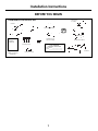
BEFORE YOU BEGIN
Ice Bucket
Icemaker
Water Valve
Assembly
Double Prong Plugs
5/8″ Icemaker
Mounting Screws
Owner’s Manual,
Installation Instructions
and Warranty
Warranty Label
ICE MAKER
WARRANTY VERIFICATION
Date Installed _____________________
Dealer____________________________
Ferrule
Flexible Plastic Tubing
Water Tube
Compression Nut
Stainless Steel Clip
Plastic Stick-On Clamp
P-Clamp (used for
water line tubing)
Owner’s Manual
&
Installation
Instructions
CONTENTS OF UK-KIT-3S

Installation Instructions
8
INSTALLING THE ICEMAKER
REMOVE THE ICE SERVICE RACK
An ice service rack is mounted on knobs secured
with screws in the left side of the freezer wall.
• Remove ice trays and storage bin.
• Carefully slide the ice rack up and off the
mounting knobs.
1
Ice
Service
Rack
• Remove and discard the screws and knobs from
the wall.
REMOVE ELECTRICAL PLUG
AND WATER CONNECTION
COVER
2
Electrical plug
and water
connection cover
• Remove screw (A) that holds the cover in place.
Discard the screw and cover.
• Push in a double prong plug to seal the cover
mounting slot.
A
Cover
mounting
slot
Double
prong plug
INSTALL WATER FILL TUBE
THROUGH THE BACK OF THE
REFRIGERATOR
3
• Remove the cover
for the water tube
inlet hole on the
back of the
refrigerator near
the bottom. Use
a flat-blade
screwdriver
covered with
masking tape to
protect against
scratching the
refrigerator.
• After removing
the cover, use the
screwdriver to
pierce the interior
sealing tape that
covers the hole for
the water
fill tube inlet.
Clear a path for
the water
fill tube.
• From the inside
of the freezer, pull the
water fill tube through
the hole in the back
wall. Be sure to
remove the masking
tape from the end of
the water fill tube to
allow water to flow
into the icemaker.
• From the outside, push
gently on the water fill
tube while twisting it
slightly, until the flange
is firmly sealed inside
the hole on the back of
the refrigerator. Make
sure the water fill tube
is completely sealed.
• To prevent the styrofoam insulation beads from
entering the water fill tube during installation,
temporarily cover the end of the tube with masking
tape. Push the water fill tube through the hole.
Masking
tape
Cover for the
water tube inlet
hole on the back
of the refrigerator
Sealing tape
(remove)
Back
wall
inside
freezer
Electrical connection
Water tube
inlet hole
Back of the
refrigerator
Back
wall
inside
freezer
Water
tube
inlet
hole
Masking
tape
Electrical
connection
Back of the
refrigerator
Sealed water
fill tube
Flange
Water fill tube
Water fill
tube

Installation Instructions
INSTALLING THE ICEMAKER
HANG THE ICEMAKER ON
FREEZER WALL
•
Slip the stainless steel clip over the wall of the
water cup.
•
Screw one 5/8″ icemaker mounting screw in the top
front hole. Leave the head out approximately 3/8″ for
the slot in the icemaker hanger to slip over the screw.
•
Hold the icemaker in position inside the freezer. Insert
the wire harness plug into the outlet using a rocking
motion, until the locking fingers on the sides of the
plug snap into place. The plug fits only one way.
•
Slip the icemaker hanger over the mounting screw,
while easing the icemaker water cup toward the end of
the water fill tube. The water fill tube fits under the
stainless steel clip on the water cup. The water fill tube
must not be kinked. It should extend approximately
1/2″ into the water cup and must not become easily
dislodged.
•
Screw in the two remaining icemaker mounting screws.
Tighten all three screws.
4
Stainless
steel clip
Start this
screw first
Hangers
Water fill
tube
Wire
harness
outlet
Water
cup
PLACE ICE STORAGE BIN ON
FREEZER SHELF.
Move the ice storage bin into place directly under
the icemaker.
NOTE: Check again to make sure the icemaker
power cord is fully inserted into its outlet.
Check again to make sure the icemaker feeler arm
is in the STOP (up) position.
6
APPLY WARRANTY LABEL TO
BACK OF REFRIGERATOR.
A label is provided in the kit. On it record the date of
the installation for warranty purposes.
7
LIFT THE ICEMAKER FEELER ARM
TO THE STOP (UP) POSITION.
The icemaker should feel secure when you lift the
arm. Leave the feeler arm in the STOP (up) position
until the refrigerator is connected to the water
supply to prevent it from operating before the water
supply connection is complete.
5
Feeler arm in STOP
(up) position
Arm down—
icemaker will
operate
Arm up—
stops operation
The icemaker installation is now complete.
Refer to the following instructions for connecting
the icemaker to the home water supply.
9

Installation Instructions
WATER VALVE INSTALLATION INSTRUCTIONS
• Attach the water valve to the lower rail using the hex
screws removed from the mounting plate. This will
assure that the water valve is electrically grounded.
• Plug the water valve wire connector into the
terminal board at the points on the bottom right
position, marked “1” and “2” across from “A”
and “B.”
• Re-install the vertical wire and tube cover. To avoid
pinching wires, carefully tuck the wires inside the
cover. Secure the cover by reusing all the original
screws.
• Secure the 1/4 inch flexible plastic tubing to the
rear wall of the refrigerator cabinet using the plastic
stick-on clamp.
NOTE: The P-clamp is used to secure the 1/4 inch
flexible tubing at the back horizontal cover, using
the existing cover screw. (See Water Line Installation
Instructions.)
INSTALL THE WATER VALVE
• Remove and save the 4 hex screws and the vertical
wire and tube cover from the back of the refrigerator.
• To access the water valve, cut along the outline in
the fiberboard cover using a utility knife. Remove
the fiberboard.
• Thread the water valve wires through the
rectangular opening, taking care not to bend any
existing tubes.
• Use a 1/4″ hex nut driver to remove the two lower
screws from the valve mounting plate and discard
the mounting plate.
Wire and tube
cover
1/4″ plastic
tubing
1/4″
plastic
tubing
Water
valve wires
Water valve
wire connector
Water
valve
Wire and
tube cover
Plastic
stick-on
clamp
1/4″ flexible
plastic tubing
Water valve
Terminal
board
Water valve
wire connector
Reuse hex screws to
mount water valve
Discard mounting plate
Remove hex screws and reuse
to mount water valve
10

Installation Instructions
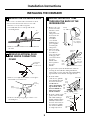
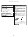
WATER LINE INSTALLATION INSTRUCTIONS
WHAT YOU WILL NEED
A cold water supply is required for automatic icemaker
operation. Water pressure must be between 20 and
120 psi.
Copper or GE SmartConnect™ Refrigerator Tubing,
1/4″ O.D., should be used to connect the refrigerator
to the water supply.
NOTE: The only GE approved plastic tubing is that
supplied in GE SmartConnect™ Refrigerator Tubing
kits. Do not use any other plastic water supply line
because the line is under pressure at all times. Certain
types of plastic will crack or rupture with age and cause
water damage to your home.
A shutoff valve should be connected to the cold water
line. The shutoff valve should have a water inlet with a
minimum inside diameter of 5/32″ at the point of
connection to the COLD WATER LINE. A saddle-type
shutoff valve permitted by many local plumbing codes
is shown below.
Check your local plumbing codes before choosing this
type of valve. We recommend using the saddle valve
supplied with GE Water Supply Kits WX8X2, WX8X3
and WX8X4. NOTE: DO NOT USE A SELF-
PIERCING VALVE.
•
CAUTION
–
When using any electrical
device (such as a power drill) during installation,
be sure the device is insulated or wired in a manner
to prevent the hazard of electric shock.
• All installations must be in accordance with local
plumbing code requirements.
WARRANTY INFORMATION
This water line installation is not warranted by the
refrigerator or icemaker manufacturer. Follow these
instructions carefully to minimize the risk of
expensive water damage.
If you use your refrigerator before connecting the
water line, make sure the icemaker feeler arm is kept
in the STOP (up) position.
11
Min. 5/32″ dia. opening
Shutoff valve
Ferrule (sleeve)
SmartConnect™
Tubing
Compression
nut
Compression
nut

Installation Instructions
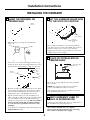
WATER LINE INSTALLATION INSTRUCTIONS
TYPICAL PLUMBING INSTALLATION
WITH WATER SUPPLY KITS WX8X2, WX8X3 and WX8X4
Sealing
washer
Shutoff valve
Ferrule
Cold water
pipe
Tubing coiled
Hole for tubing
P-clamp
Compression nut
SmartConnect™ Tubing
Refrigerator
connection
Compression nut
1/4″ Fitting
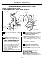
SHUT OFF MAIN WATER SUPPLY
• Open the closest cold water faucet to clear water
from the line.
1
INSTALL SHUTOFF VALVE ON
NEAREST COLD FREQUENTLY
USED DRINKING WATER LINE
• Choose a location for the valve that is easily
accessible. It is best to connect into the side of a
vertical water pipe. When it is necessary to connect
into a horizontal water pipe, make the connection to
the top or side, rather than at the bottom, to avoid
drawing off any sediment from the water pipe.
• Drill a 1/4″ hole in one wall of the water pipe, using
a sharp bit. Remove any burrs resulting from
drilling the hole in the pipe.
• Tighten the clamp screws until the sealing washer
begins to swell.
2
ROUTE WATER SUPPLY TUBING
BETWEEN COLD WATER LINE
AND REFRIGERATOR
• Route tubing where the temperature remains above 35°F.
• Then route the tubing through a hole drilled in the
floor (behind the refrigerator or adjacent base cabinet)
as close to the wall as possible. Be sure there is sufficient
extra tubing (about 8 feet coiled into 3 turns of about
10 inches diameter) to allow the refrigerator to move
out from the wall after installation.
3
CONNECT WATER SUPPLY
TUBING TO SHUTOFF VALVE
If using copper tubing, place the compression nut and
ferrule onto the end of the tubing and connect to the
shutoff valve. Make sure the tubing is fully inserted into
the valve. Tighten the compression nut securely, then
pull on the tube to check for a secure connection.
DO NOT OVERTIGHTEN.
For plastic tubing from a GE SmartConnect™
Refrigerator Tubing Kit, insert the molded end of the
tubing into the shutoff valve and tighten compression nut
until it is hand tight, then tighten one additional turn with
a wrench. Overtightening may cause leaks.
4
12
Ferrule
SmartConnect™
Tubing
Compression
nut

Installation Instructions
WATER LINE INSTALLATION INSTRUCTIONS
SET THE ICEMAKER FEELER
ARM TO THE ON (DOWN)
POSITION
The icemaker will not begin to operate until it reaches
its operating temperature of 15°F. or below. It will then
begin operation automatically.
8
CONNECT WATER SUPPLY
TUBING TO REFRIGERATOR
Before making connection to the refrigerator, be sure
refrigerator power cord is not plugged into wall outlet.
• Turn water on and flush out the tubing, making
certain that all foreign matter is removed from the line.
• Shut the water off after about 1 quart of water has been
flushed through the tubing.
NOTE: Some localities may have sand or other foreign
matter present in the water supply in such quantities that
they may, in time, collect in the screen of the water valve
attached to the back of the refrigerator and tend to reduce
the water flow to the icemaker. Where such conditions
exist, we recommend that an additional filter or strainer
be installed in the line near the refrigerator. If a screen
type strainer is used, it should be 80 mesh or finer.
• Remove the plastic cap from the water valve and plastic
tube assembly.
• If using copper tubing, cut off the flared end of the
copper tubing and remove the flare nut from the
tubing. Place the 1/4″compression nut and ferrule
onto the end of the copper tubing as shown on page
12. Insert the end of the water supply tubing into the
water valve as far as possible. While holding the tubing,
tighten the fitting, then pull on the tube to check for a
secure connection. DO NOT OVERTIGHTEN.
• If using plastic tubing from a GE SmartConnect™
Refrigerator Tubing Kit, insert the molded end of the
tubing into the refrigerator connection and tighten the
compression nut until it is hand tight, then tighten one
additional turn with a wrench. Overtightening may
cause leaks.
• Secure the 1/4 inch flexible water supply tubing
with the P-clamp at the back horizontal cover, using
the existing cover screw.
5
TURN ON WATER AND CHECK
ALL JOINTS FOR LEAKS
Tighten fittings if required to stop leaks.
6
PLUG REFRIGERATOR POWER
CORD INTO APPROPRIATE
ELECTRICAL OUTLET
7
MOVE THE REFRIGERATOR
BACK TO THE WALL
Arrange the coil of copper tubing so that it does not
vibrate against the back of the refrigerator or against
the wall. Make sure the water supply tubing does not
get kinked.
9
NOTE: The first few batches of cubes should be
thrown away, so that remaining impurities in the water
line will be flushed out.
Wire and
tube cover
Plastic
stick-on
clamp
1/4″ plastic
tubing
Water valve
Water supply
tubing
P-clamp
Back
cover
screw
13

14
Notes.

15
Icemaker Warranty.
All warranty service provided by our Factory Service Centers,
or an authorized Customer Care
®
technician. To schedule service,
on-line, 24 hours a day, visit us at www.GEAppliances.com,
or call 800.GE.CARES (800.432.2737).
■Service trips to your home to teach you how to use
the product.
■Improper installation.
You are responsible for providing adequate electrical,
plumbing and other connecting facilities, including the
water line to the icemaker and the water line installation.
■Failure of the product if it is abused, misused, or used for
other than the intended purpose or used commercially.
■Replacement of house fuses or resetting of circuit breakers.
■Damage to the product caused by accident, fire, floods or acts
of God.
■Incidental or consequential damage caused by possible
defects with this appliance.
What GE Will Not Cover:
This warranty is extended to the original purchaser and any succeeding owner for products purchased for home use
within the USA. In Alaska, the warranty excludes the cost of shipping or service calls to your home.
Some states do not allow the exclusion or limitation of incidental or consequential damages. This warranty gives you
specific legal rights, and you may also have other rights which vary from state to state. To know what your legal rights
are, consult your local or state consumer affairs office or your state’s Attorney General.
Warrantor: General Electric Company. Louisville, KY 40225
Staple your receipt here.
Proof of the original purchase
date is needed to obtain service
under the warranty.
For The Period Of: GE Will Replace:
One Year Any part
of the icemaker which fails due to a defect in material or workmanship. During this
From the date of the full one-year warranty,
GE will also provide,
free of charge,
all labor and in-home service to replace
original purchase
the defective part.

Printed in the United States
Consumer Support.
GE Appliances Website
www.GEAppliances.com
Have a question or need assistance with your appliance? Try the GE Appliances Website 24 hours a day,
any day of the year! For greater convenience and faster service, you can now download Owner’s Manuals,
order parts, catalogs, or even schedule service on-line. You can also “Ask Our Team of Experts
™
”
your questions, and so much more...
Schedule Service
www.GEAppliances.com
Expert GE repair service is only one step away from your door. Get on-line and schedule your service at
your convenience 24 hours any day of the year! Or call 800.GE.CARES (800.432.2737) during normal
business hours.
Real Life Design Studio
www.GEAppliances.com
GE supports the Universal Design concept—products, services and environments that can be used by
people of all ages, sizes and capabilities. We recognize the need to design for a wide range of physical and
mental abilities and impairments. For details of GE’s Universal Design applications, including kitchen
design ideas for people with disabilities, check out our Website today. For the hearing impaired, please call
800.TDD.GEAC (800.833.4322).
Extended Warranties
www.GEAppliances.com
Purchase a GE extended warranty and learn about special discounts that are available while your warranty
is still in effect. You can purchase it on-line anytime, or call 800.626.2224 during normal business hours.
GE Consumer Home Services will still be there after your warranty expires.
Parts and Accessories
www.GEAppliances.com
Individuals qualified to service their own appliances can have parts or accessories sent directly to their homes
(VISA, MasterCard and Discover cards are accepted). Order on-line today, 24 hours every day or by phone at
800.626.2002 during normal business hours.
Instructions contained in this manual cover procedures to be performed by any user. Other servicing generally
should be referred to qualified service personnel. Caution must be exercised, since improper servicing may cause
unsafe operation.
Contact Us
www.GEAppliances.com
If you are not satisfied with the service you receive from GE, contact us on our Website with all the details
including your phone number, or write to: General Manager, Customer Relations
GE Appliances, Appliance Park
Louisville, KY 40225
Register Your Appliance
www.GEAppliances.com
Register your new appliance on-line—at your convenience! Timely product registration will allow for
enhanced communication and prompt service under the terms of your warranty, should the need arise.
You may also mail in the pre-printed registration card included in the packing material, or detach and
use the form in this Owner’s Manual.
-
 1
1
-
 2
2
-
 3
3
-
 4
4
-
 5
5
-
 6
6
-
 7
7
-
 8
8
-
 9
9
-
 10
10
-
 11
11
-
 12
12
-
 13
13
-
 14
14
-
 15
15
-
 16
16


Ask a question and I''ll find the answer in the document
Finding information in a document is now easier with AI
Related papers
Other documents
-
Dometic NRX Clip Installation guide
-
Hotpoint HPS18BTHBB User manual
-
AMERICANA Americana A3316ABS User manual
-
Whirlpool ECKMFEZ2 Installation guide
-
Whirlpool ECKMF-83 User manual
-
Whirlpool ECKMF95 Installation guide
-
-
-
-