Whirlpool ECKMF95 Installation guide

Category
Fridges
Type
Installation guide

This manual is also suitable for

Whirlpool ECKMF95 allows you to make your own ice cubes right at home, with an optional water filtration system for improved taste. Easily add modular ice maker to your compatible Whirlpool refrigerator to have a steady supply of ice on hand.

Whirlpool ECKMF95 allows you to make your own ice cubes right at home, with an optional water filtration system for improved taste. Easily add modular ice maker to your compatible Whirlpool refrigerator to have a steady supply of ice on hand.

Y
1
Table of
Contents
(complete)
. . . . . . . . . . . . . . . . . . . 2
Requesting
Assistance
of
Service
..,,...................
2
cmpoftant
Inf of
mation
. . .3
Before
You Begin
. . . . . . . . . . 4
Installing
the
Ice Maker
.,...... . . . . . . . . . . . . . . . . 6
1
I
Installing
the
Water une
. . . . . . . . . . . . . . . . . . . .
16
Final installation .,........ 22
Starting
the
ice
Maker
. . . . . . . . . . . . . . . . . . . . . . 24
TrOubleshOOting
. . . . . . . . . .
25
MODULAR
ICE MAKER KIT
PART NO. 2155462 Rev.
A
Table of Contents
Page
Requesting Assistance or Service
..........
.2
important Information
..............................
3
Before You Begin
....................................... 4
Tools
........................................................
4
Installation notes
......................................
4
Important safety instructions
................... .4
Components
............................................ 5
installing the ice Maker
.............................. 6
Making preparations
................................
6
Side-by-side models ...............................
.7
Top/bottom freezer models..
................... .9
Installing the tubing clips.. ......................
10
Preparing the water valve tubing
(for bottom freezers only).
......................
11
Mounting the water valve..
.....................
12
Connecting the water valve tubing..
...... .I3
Mounting the ice maker
.........................
14
installing the Water Line
..........................
16
Choosing a location ...............................
16
Page
Routing the copper tubing . . . . . . . . . . . . . . . . . . . . . . 17
Installing the shut-off valve
. . . . . . . . . . . . . . . . . . . . 18
Connecting the copper tubing
to the shut-off valve
. . . . . . . . . . . . . . . . . . . . . . . . . . . . . . .
19
Connecting the copper tubing
to the water valve . . . . . . . . . . . . . . . . . . . . . . . . . . . . . . . . . . . 20
Turning the water on . . . . . . . . . . . . . . . . . . . . . . . . . . . . . . 21
Final installation
. . . . . . . . . . . . . . . . . . . . . . . . . . . . . . . . . . . . . . .
22
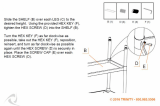
Installing the access cover and
forming
the copper tubing
. . . . . . . . . . . . . . . . . . . . . . 22
Connecting the power/
leveling the unit
. . . . . . . . . . . . . . . . . . . . . . . . . . . . . . . . . . . . . .
23
Starting the
ice
Maker . . . . . . . . . . . . . . . . . . . . . . . . . . . . . . 24
Troubleshooting
. . . . . . . . . . . . . . . . . . . . . . . . . . . . . . . . . . . . . . .
25
Operational
notes
. . . . . . . . . . . . . . . . . . . . . . . . . . . . . . . . . . 25
Troubleshooting
chart
. . . . . . . . . . . . . . . . . . . . . . . . . . . . 25
The modular ice maker service sheet . . . . 26
Ice maker replacement parts list . . . . . . . . . . . . 27
Requesting Assistance or Service
If you need assistance, contact your dealer, or see the Warranty that is included with this kit for
a toll-free number to call.
If you are not satisfied with how a problem is solved, contact the Major Appliance Consumer
Action Program (MACAP). MACAP consists of a group of independent consumer experts that
voices consumer views at the highest levels of the major appliance industry.
Contact MACAP only when the dealer, authorized servicer, and Whirlpool have failed to
resolve your problem.
Write to:
Major Appliance Consumer Action Program
20 North Wacker Drive
Chicago, IL 60606
MACAP will, in turn, inform us of your action.
3
Important Information
The following information is used throughout this installation Guide. Read it carefully SO you
are familiar with it.
information that alerts you to potentially
dangerous conditions. These conditions
can cause serious personal injury if the
suggested procedures are not observed.
@This Installation Guide gives you complete
instructions on how to install the Ice Maker
Kit in your refrigerator-freezer and connect a
water line to it. Please read the guide care-
fully and follow the instructions exactly as
described. Also, make sure that you observe
all of the ‘safety” instructions.
*This kit is designed so that almost anyone
can install it; however, a certain amount of
mechanical ability is required.
l
Before you start to install your Ice Maker Kit,
you will have to purchase a copper tubing kit
that contains a “Regular Valve and Clamp
Assembly” (for refrigerators with an auto-
matic ice maker, or self-filling trays). The kit
contains all of the hardware necessary to
connect your ice maker to the water supply.
You can purchase one at most hardware or
plumbing supply stores.
@DO NOT USE PIERCING-TYPE, OR %r”
SHUT-OFF VALVES. They reduce the flow
of water to the ice maker, and are easily
clogged.
@DO NOT USE POLYETHYLENE TUBING to
connect the ice maker to the water line. Use
only ‘!4” (O.D.) copper tubing.
I
CUSTOMER INSTALLATION IS NOT
WARRANTED BY THE REFRIGERATOR
OR ICE MAKER MANUFACTURER.
I
R
Before You Begin
Tools
You will need these tools to install your kit.
1. Regular screwdriver
2. Phillips screwdriver
3.
%6”
and l/i’ open-end wrenches (or an
adjustable wrench)
4. Pliers
5.%* nut driver
6. Hand drill with 1/4* drill bit
7. Small hand level (optional)
8. Small %-round file
9. Tubing cutter
10. Center punch
11. Hammer
12. Scissors
13.Ruler
14. Step stool (optional)
Installation notes
1. Follow the instructions carefully. Read
through the entire step so that you under-
stand it before you perform it.
2.The illustrations in this Installation Guide
are meant to clarify the installation steps
you need to perform. For each set of steps
shown, refer to the diagram immediately
beside or below the text for clarification.
Some illustrations also contain ‘DETAILS.”
DETAILS are contained in bubbles along-
side the larger illustration. A DETAIL shows
a close-up illustration of a certain portion of
a diagram or an illustration of a specific step
you are to perform. DETAILS are labeled A,
B, or C and are clearly referenced in each
step.
3. When you are instructed to install a part,
position the part as shown in the illustration.
Important safety instructions
Electrical Shock Hazard
If you intend to use power tools, such as
an electric drill, during the installation,
make sure that the AC receptacle is
properly grounded in accordance with the
National Electrical Code (ANSVNFPA 70)
and all local codes and ordinances. The
tools must have a 3-prong grounding plug
(see illustration) to minimize the danger
of electrical shock. If a mating receptacle
is not available, it is the personal respon-
sibility of the customer to have a properly
grounded 3-prong wall receptacle and
plug installed by a qualified electrician.
Failure to follow this instruction could
result in death or personal injury.
3-prong
grounding-
8prong
type wall
grounding receptacle
plug \
Correct power receptacle and plug configuration
A
Components
Remove the contents from the shipping carton
and set them on a table where they can be
easily identified and located. Check all of the
components in the kit against the following list
to help you become familiar with them. When
you identify a component, place a check
mark ( 3) after it. The KEY numbers corre-
spond to the “Component Illustrations.”
IMPORTANT: When you remove the water
valve and flexible tubing from the Styrofoam
packing insert, do not remove the tubing from
the valve. It has been factory-installed and
leak-tested. Do not disturb the compression
nut that connects the tubing to the valve, or
the valve may leak after you connect it to the
water supply.
Do not discard any of the packing material
until you account for all of the components. If
you need to order a replacement part for the
Ice Maker, a replacement parts list is provided
on page 27.
KEY QTY. DESCRIPTION
1 1 Ice maker
2 1 Ice bucket
3 1 Water valve w/tubing
4 1 Fill tube
5 1 Gasket
6 1 Short extension tube
7 1 Long extension tube*
8 2 ice maker clips*
9 2 Tubing clips
10 1 Metal water tube insert
11 1 Water valve tubing clamp
12 4 % hex-head sheet-metal screws
13 2 N’hex-head machine screws
14 2 %’ hex-head sheet-metal screws
l
For installation in Side-By-Side Models only.
COMPONENT ILLUSTRATIONS
Installing the Ice Maker
Making preparations
Refer to the illustration below for the
following steps.
1. Carefully pull the refrigerator away from
the wall so that you can easily access the
rear panel.
Electrical Shock Hazard
I
Unplug the refrigerator’s power cord from
the AC wall outlet.
Failure to do so could result in death or
serious injury.
you open the freezer door to work inside that
IMPORTANT: If you have a side-by-side
model refrigerator-freezer, be careful when
3.On an appliance with
a
bottom freezer,
remove the slide-out basket, the ice cube
trays, and the wire ice cube holder (if
necessary, refer to your “Use and Care
Guide” for the procedure). Set these items
aside.
bottom freezer models” on page 9.
On top-mount models without a full-width
freezer shelf, remove the ice tray shelf.
Place the shelf aside, as you will use it
later to support the ice bucket.
If you have
a
side-by-side model refrigera-
tor, proceed to “Side-by-side models” on
page 7. If you have a refrigerator with a top
or a bottom freezer, proceed to “Top/
you do not force the door against the stop at
the bottom of the door. If you bend the stop,
the door will not close properly.
2.On appliances with a top or a bottom
freezer, open the freezer door and remove
all of the food items from inside the freezer
compartment.
For side-by-side units, you should only
have to remove food items from the top half
of the freezer section. This should give you
enough room to access the areas to install
NOTE: The work area for all three model
refrigerator-freezers is shown in DETAIL A
below.
YDETNLA\
the ice maker.
Rear wall
9
Power \
cord
plug =I
_ .
receptacle
receptacle
I
RBar wall
\
ly
P>wer
cord \:
plug ant
receptac
Rear wall
K
lop
freezer model
Bottom freezer model
Sk&by-eide model
Work areas on the three model
refrigerator-freezers
Side-by-side models
Refer to the side diagram for the following
steps. You will be working inside the freezer
compartment.
1. Remove the phillips screw from the ice
maker wiring cover and remove the cover.
2. Refer to DETAIL A, and with a pair of pliers,
break away the tabs from the wiring cover
and discard them.
3. Insert the blade of a small screwdriver
under the edge of the round hole plug for
the fill tube, (located at the back of the
freezer liner), and pry it out. You can dis-
card the plug.
Refer to the side diagram for the following
steps. You will be working on the outside at
the rear of the cabinet.
1. In the upper right corner of the cabinet, peel
off the label that is over the fill tube hole.
2. Pull the foam insert out of the fill tube hole
and discard it.
Refer to the side diagram for the following
steps.
1. Locate the fill tube and the round foam
gasket from the ice maker kit (the gasket
may already be installed on the fill tube). If
not already done, slide the gasket over the
end of the fill tube.
2. Insert the fill tube through the hole in the
rear of the refrigerator with the spout facing
down, and secure it with two lh” hex-head
sheet-metal screws.
ln8ert pin
0
Wiring
harness
c)
slot
Phillips
.++ 8crew
Tab
Insert tab
into slot
Break off and discard
Ice maker wiring cover
000
Foam insert
Removing the label and foam plug
spout
/ I
Foam
gasket
I I
Installing the fill tube/gasket
7
Refer to the side diagram for the following
step. You will be working inside the freezer
compartment.
1. Position the long aluminum fill tube exten-
sion so that the curve is pointing down, and
slide the flared end over the fill tube as far
as it will go (see DETAIL A). Some kits may
have a long straight plastic extension in
place of the long bent aluminum extension.
Install the plastic extension by sliding it over
the fill tube as far as it will go.
Refer back to the side diagram for the
following step.
2. Position the wiring harness so that it is
through the slot in the wiring cover. Insert
the tab at the back of the wiring cover into
the freezer liner slot. Press the pin on the
side of the wiring cover into the hole in the
side of the freezer liner so it locks into
place. Secure the wiring cover with the
phillips screw you removed earlier.
Proceed to “Installing the tubing clips” on
page 10.
w
tiring hard
@
- %&s-
-I -5
AL
pointing down
Long fill
tube extension
A
w-
I
Installing the long fill tube extension
an pm
Ihole
qliole cover
HOI
0
Wring
harnesa
c)
0
Wiring
cover
Replacing the ke maker wiring cover
8
Top/bottom freezer models
Refer to the side diagram for the following
steps.
1. Remove the phillips screw from the ice
maker wiring cover, unhook the right side
tab from the edge of the back cover, and
remove the wiring cover.
2. Look at the back side of the wiring cover
and note the grooved lines. Use a pair of
pliers and bend the areas inside the
grooved lines back and forth until they
break away from the wiring cover.
Refer to the side diagram for the following
steps.
1. Pull the 4-wire ice maker harness out from
behind the freezer’s back cover as far as
possible, and hang it over the edge of the
cutout. Do not remove any other wiring from
the cutout.
2. Slide the flared end of the short aluminum
fill tube extension or the short plastic fill
tube extension over the end of the fill tube
as far as it will go (see DETAIL A).
3. Refer to DETAIL B and install the wiring
cover over the fill tube with the wiring har-
ness through the slot. Hook the tab in the
side of the wiring cover into the slot in the
back cover of the freezer, and secure the
cover with the phillips screw you removed
earlier.
Mounting hole -
Phillips
screw
Tab
Wiring
Removing the wiring panel
DETAlL A
d 14
extension
ab
Installing the short fill tube extension
and reinstalling the wiring panel
Installing the tubing clips
Refer to the side diagram for the following
steps.
1. Remove the seven hex-head screws from
the rear access cover, then remove the
cover and set it aside.
NOTE: If you have a later unit with a metal
panel, (see DETAIL A), remove the hex-
head screw from the access cover. Discard
the cover and its screw. Do not remove the
7 hex-head screws from the larger rear
access cover.
2. Peel the backing from the adhesive sides of
the tubing clips. Press the clips against the
back of the cabinet in the right channel at
the approximate locations shown in DETAIL
B. Center the clips between the fill tube (an
alternate fill tube design is shown in
DETAIL C) and the top of the access
opening.
If you have a bottom freezer, proceed to page
11. If you have a side-by-side (SXS) or a top
freezer unit, proceed to page 12.
DETAlL C
Fill tube for b
freezer mode
Fill tube for
top and SXS
freexerr only
Right
/
channel
rDETAlL B 9
Tubing
clio
Top and SXS
freezers
Tubing
CliD
Bottom
freexere
acces8 cover
DETAlLA -
Installing the tubing clips
18x-
10
Preparing the water valve tubing
(for bottom freezers only)
Refer to the side diagram for the following
steps.
CUT TUBING
HERE
1. Untape the coiled flexible tubing coming
from the water valve and straighten it.
2. Starting at the top of the compression nut
on the water valve, measure the tubing for
30: and mark the location on the tubing
with a pen.
3. Use a pair of scissors or a hobby knife, and
make an even cut across the water valve
tubing at the 30’mark you made in the
previous step. Discard the excess tubing.
I II
MAKE AN
EVEN CUT
ACROSS
w
Compression nut
Water valve
/
Preparing the water valve tubing
(for bottom freezers only)
11
Mounting the water valve
Refer to the diagram below for the following
steps.
1. Locate the 2-pin water valve solenoid
3. Refer to DETAIL B and mount the water
connector (with the brown and two white
valve to the mounting holes in the cabinet
wires) that is taped to the main wiring
frame with two X’hex-head machine
harness at the lower right corner of the rear
screws. Make sure that you tighten these
access (see DETAIL A).
two screws securely.
2. Refer to DETAIL B and insert the 2-pin
connector over the water valve solenoid
terminals as far as possible (if the harness
is not long enough, break the tape holding it
to the main harness). You can position the
connector with the wires at either terminal.
Mounting the water valve
/
DETAIL A -\
f
/
DETAIL B
H’ hex-head
machine screwa
Connecting the water valve tubing
Refer to the diagram below for the following
steps.
1. Refer to the inset in DETAIL A and pull the
plastic insert out of the fill tube spout and
discard it.
2. Locate the water valve tubing clamp (from
the ice maker kit), and note that one of the
flanges is made for a threaded screw and
4. Refer to DETAIL 6, and slide the end of the
tubing into the end of the fill tube spout as
far as it will go (if the tubing does not
reach, pull as much as necessary up
through the clips), then tighten the tubing
clamp screw as much as possible. Pull on
the tubing to make sure that it is secure. If
it slides out of the spout, push it back in,
and tighten the clamp screw further until
the tubing is secure.
the other side has a round hole. Position
this clamp with the round hole side facing
5. Press the tubing into the two clips (see
up, and slide it over the end of the spout
DETAIL C) you installed earlier on the back
(see DETAILS A and 6). Thread a 55” hex-
of the cabinet. You will connect the free
head sheet metal screw into the clamp with
end of the tubing later.
your fingers as far as possible. You will
tighten the screw later.
3. Refer to DETAIL A, and position the metal
water tube insert as shown, then press it all
6. Pull any excess tubing near the fill tube
down throuah the two clamps so it forms a
straight line-with a loop at the bottom of the
water valve.
the way into the water valve tubing.
II -
P
DETAlL B
‘Tighten\
Slide clamp
d
over spout +
-.. . .
wrew on
*
spout a8
much as
possible
Fill tub
HF
I=
Insert tubinf
into spout
a8 far a8
poesible
I
DETAIL A
,
*pout
Water valve
tublng clamp
H’ hex-head
sheet-metal
Connecting the water valve tubing to the fill tube
Refer to the side diagrams for the following
steps.
1. Position the ice maker inside the freezer
compartment and connect its wiring con-
nector to the wiring harness connector so
they lock together (the locking arm will snap
over the raised tab). The connectors will fit
together only one way.
2. For Top/Bottom Freezers Only:
Hang the
ice maker over the two hex-head screws
you installed earlier. Make sure that the
bottom mounting bracket hole is aligned
with the mounting hole in the freezer liner,
then tighten the two top hex head screws.
Be careful not to over-tighten the screws.
3. For Side-By-Side Models Only:
Position the
ice maker so that its top and bottom mount-
ing tabs are flat against the side of the
freezer liner. Center the top tabs under the
two mounting clips, and push the ice maker
straight up so that the mounting clips snap
over the tabs and lock into place (you
should hear them ‘click” as they lock).
4. Mount the bottom bracket of the ice maker
to the freezer liner mounting hole with a %”
hex-head sheet-metal screw.
screw
Mounting the ice maker
(top and bottom freezers)
bracket
connectors
Mounting the ice maker
(sideby-side models)
15
Installing the Water Line
Choosing a location
1. Open the copper tubing kit that you pur-
chased earlier, and lay the contents neatly
on a table where you can identify them
easily. The parts from the kit that you will
use are as follows:
1
Regular Valve (not the steel-
piercing type)
2 Compression Sleeves
2 Compression Nuts
2 Clamps
2 Screws
2 Nuts
1 Gasket Seal
1
Length of Coiled Copper Tubing
NOTE: When you work with the soft copper
tubing, be careful not to kink it. If you acciden-
tally kink the tubing, do not use it.
IMPORTANT: Do not install water line tubing
in a location where the temperature may fall
below freezing; otherwise, property damage
could occur.
2. Choose a suitable water pipe location to
install the water shut-off valve (see side
diagram for some suggested locations). We
recommend installing the valve on a vertical
length of cold (not hot) water pipe that is
nearest your refrigerator. If a vertical length
of pipe is not nearby, you can use a hori-
zontal length of water pipe, however, you
will have to drill the access hole for the
valve into the top or side of the pipe (not the
bottom). This will keep water in the pipe
from flowing down onto the drill, and also
keep sediment from collecting in the valve
later.
NOTE: Depending on the location of the
horizontal pipe in relation to the floor and
wall, drilling into it may not be possible.
3. Drill a %‘hole through the floor or wall to
the water pipe.
Through
Under rink
Through
In crawl
floor to
tocold
wall to
space
basement
water pipe
utility room
under
cold water
cold water
home to
Pii=
Pipe
cold water
Pipe
Typical water pipe locations
Electrical Shock Hazard
Make sure there are no electrical wires
underneath the floor where the hole is to
be drilled.
Before drilling, put on safety glasses to
avoid eye injury.
Failure to follow these instructions could
result in death or personal injury.
16
Routing the copper tubing
Refer to the side diagram for the following
steps.
1. Uncoil the necessary length of copper
tubing and straighten it, then route the end
of the tubing through the access hole you
drilled to the location you have chosen to
install the shut-off valve. Straighten only
enough of the copper tubing to reach this
location. Leave the rest coiled near the
access hole.
2.At this time, make sure that you have been
supplied with enough tubing so that when
you are finished connecting the water line,
you will have enough coiled behind the
refrigerator to easily move it forward far
enough to clean behind it. Also make sure
that the coils are large enough so that when
the unit is pulled forward, the windings will
not stretch too far and kink.
3.Turn off the cold water supply going to the
water pipe where you will be installing the
shut-off valve.
4. Open a cold water tap that is connected to
the selected water pipe and bleed off the
water pressure. Leave the tap open until
after you complete the water line hook up.
5. Use a hammer and a center punch, and
mark the location of the hole for the shut-off
valve. If you are marking copper tubing, do
not strike the punch hard enough to bend it.
6. Install a l/4* bit in the drill, and carefully
drill an access hole through just the front
side (not through both sides) of the cold
water pipe.
7. Check the hole and make sure that you
have drilled completely through one side of
the pipe. The edges of the hole should be
smooth and round. If necessary, use a
small %-round file to remove any rough
edges from inside the hole, and any burrs
from around the top of the hole.
vertical water
Routing the copper tubing
Electrical Shock Hazard
If you are using an electric drill, make
sure it is properly grounded. Some water
usually remains in the pipe, and could
enter the drill while you are using it.
Before drilling, put on safety glasses to
avoid eye injury.
Failure to follow these instructions could
result in death or personal injury.
Installing the shut-off valve
Refer to the diagram below for the following
steps.
1. Locate the shut-off valve and the front pipe
clamp (with the threaded hole in the center)
from the copper tubing kit. Then, being
careful not to crossthread the valve, screw
the end with the pilot tube into the threaded
hole of the clamp. Hand-tighten the valve
as far as it will go (the threaded shaft is
slightly tapered and can only be tightened
so far).
2. Use a %*open-end (or adjustable) wrench,
and turn the body of the shut-off valve an
additional l/e -turn to secure it to the clamp.
3. Slide the rubber seal gasket (from the
copper tubing kit) over the pilot tube (the
unthreaded portion) of the shut-off valve.
Nut -
4. Carefully slide the pilot tube of the shut-off
valve into the water pipe access hole so it
is against the seal gasket, and install the
back pipe clamp over the water pipe.
Secure the clamps to the pipe with the two
screws and nuts that were supplied with
the copper tubing kit. Tighten the nuts
equally so that the space between the
clamps is the same (see DETAIL A). DO
NOT OVERTIGHTEN the nuts, or you
could deform the clamps and damage the
seal gasket.
f-
DETAIL A -
I .
Scrw +
6
Pilot tube -
Shutoff valve
T6
LJ
Mounting the shut-off valve
to the water pipe
Connecting the copper tubing to the shut-off valve
Refer to the diagram below for the following
steps.
1. Straighten a 2” section of copper tubing and
make sure that the opening is round and
cut evenly across the end. If necessary, use
a tubing cutter (or a hacksaw) and cut the
end off, then file it so it is even, and remove
any burrs from around the inside and out-
side edges so it is smooth and round. When
you are finished, clean the filings from
inside the tubing as much as possible.
2. Position the compression nut as shown,
and slide it over the end of the copper
tubing.
3. Slide a compression sleeve over the
copper tubing until it is approximately
1 ‘from the end.
4. Insert the end of the copper tubing into the
outlet connector of the shut-off valve as far
as it will go, and then hand tighten the
compression nut as much as possible.
Compression nut
J
r\+
)t .I
Outlet
5. Use a l/2” open-end wrench, and further
tighten the compression nut on the shut-off
valve
one additional turn.
If necessary, you
will tighten the nut further after you turn on
the water supply.
6.Turn the T-handle on the shut-off valve to
its fully “open” (counterclockwise rotation)
position.
I
Compression
Wv=r
tubing
Connecting the copper tubing to the shut-off valve
Connecting the copper tubing to the water valve
Refer to the diagram below for the following
steps.
1. Check to make sure that the free end of
the tubing is round and cut even. If neces-
sary, prepare the end in the same manner
as you did earlier. Be sure to clean the
filings from inside the tubing after you
prepare the end.
When you perform the next step, be careful
not to kink the copper tubing.
2. Starting at the free end, straighten ap-
proximately 20” of the copper tubing.
3. Close the water tap you left open earlier to
bleed the water lines.
4. Insert the end of the copper tubing into a
pail, and have someone turn on the water
supply. Allow enough water to flow
through the lines to thoroughly flush them
out. Once the water runs clear, turn off the
supply and bleed the lines.
5. Remove the strain relief clamp from the
rear of the cabinet and slide it over the end
of the copper tubing. Make sure you posi-
tion the flanges as shown.
6. Slide a compression nut over the free
end of the copper tubing.
7. Slide a compression sleeve over the
copper tubing and position it 1 “from
the end.
8. If one is installed, remove the plastic cap
from the water inlet fitting on the water
valve and discard the cap.
9. Insert the end of the tubing into the water
inlet connector at the top of the water
valve as far as it will go, and hand tighten
the compression nut as much as possible.
10. Use a % * open-end wrench, and further
tighten the compression nut
on
the water
inlet connector
gne additional turq.
If
necessary, you will tighten the nut further
after you turn on the water supply.
11. Mount the strain relief clamp to the back
of the cabinet with the hex-head screw
you removed earlier.
Mounting screw
Copper tubing
Compression
nut
Watec inlet
fitting
Connecting the copper tubing
to the water valve
20
  • Page 1 1
  • Page 2 2
  • Page 3 3
  • Page 4 4
  • Page 5 5
  • Page 6 6
  • Page 7 7
  • Page 8 8
  • Page 9 9
  • Page 10 10
  • Page 11 11
  • Page 12 12
  • Page 13 13
  • Page 14 14
  • Page 15 15
  • Page 16 16
  • Page 17 17
  • Page 18 18
  • Page 19 19
  • Page 20 20
  • Page 21 21
  • Page 22 22
  • Page 23 23
  • Page 24 24
  • Page 25 25
  • Page 26 26
  • Page 27 27
  • Page 28 28

Whirlpool ECKMF95 Installation guide

Category
Fridges
Type
Installation guide
This manual is also suitable for

Whirlpool ECKMF95 allows you to make your own ice cubes right at home, with an optional water filtration system for improved taste. Easily add modular ice maker to your compatible Whirlpool refrigerator to have a steady supply of ice on hand.

Ask a question and I''ll find the answer in the document

Finding information in a document is now easier with AI