Page is loading ...

936.2079/A/0206/1.8e
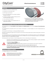
Offset parabolic antenna CAS 120
for one, two or three feed systems CAS 120/G
CAS 120/R
1. Intended use
The parabolic antenna CAS 120 is exclusively destined
for:
– reception of satellite signals
and
– utilisation as a domestic antenna.
A domestic or private antenna is defined acc. to
DIN 4131 as an antenna with a free mast length of 6 m
and a bending moment at the fixing point of up to
1650 Nm.
– installation on buildings not subject to oscillations.
The antenna may only be mounted with the support
ZAS 120, order. no 218672.
The ZAS 120 is not included in the scope of delivery of
the parabolic antenna.
It is important to observe the maximum load as
mentioned in the technical data (right column).
If that value is exceeded, antenna parts can break
loose!
The parabolic antenna CAS 120 can be equipped with
– one feed system (LNB) for reception of signals from
one satellite.
– two or three feed systems for multifeed reception from
two or three satellites 3°–4° or 6° apart.
Neither the feed systems nor the mounting instructions
for the feed systems are included in the scope of delivery
of the antenna.
Attention!
Do not use the parabolic antenna for purposes other
than mentioned in these instructions.
Never
● modify any antenna parts or
● use different components than those specifically
recommended by the manufacturer for use with
these antennas.
As a result of that, the stability and security of the
antenna can be affected.
2. Technical data
The parabolic antennas CAS 120 complies with the
specifications acc. to DIN EN 50083-1.
Diameter of reflector: Width: 1234 mm
Height: 1335 mm
Length of the support arm: 1160 mm max. from
centre of mast
LNB support: Swivelling support for the
adapter plate for mounting
up to 3 Kathrein feed
systems
Measurements (packed): 1500 x 1335 x 225 mm
Weight (packed): 29 kg
Weight (unpacked): 18.5 kg
Diameter of mast: 50-90 mm
Elevation angle: 5°-50°
Azimuth angle: 0°-360°
Wind surface area: 1.35 m
2
Vibration immunity: ETS 300019-2-4 (12.94)
IEC Class 4 M 5
Windload 1: 1296 N
for an installation height: up to 20 m above ground
for a wind velocity: up to 130 km/h
at a dynamic pressure: 800 N/m
2
Windload 2: 1776 N
for an installation height: higher than 20 m above
ground (factor 1.37)
for a wind velocity: up to 150 km/h
Maximum load: 2646 N
at a dynamic pressure: 1900 N/m
2
(190 km/h)
Attention! If the max. load is exceeded, antenna parts
can break loose!
Fig. 1

936.2079/A/0206/2.8e
3. Before you…
begin to install, connect or utilise the parabolic antenna,
observe the information you find in these mounting
instructions. If you fail to pay attention to the information,
one cannot exclude
that due to wrong installation and connecting, or be-
cause of having modified components or using other
components, the antenna or the mounting place will
be damaged.
that because of inappropriate behaviour, risks for your
and other people's health and life will be created.
that the manufacturer will decline the liability for faulty
function and resulted damages.
It is most important that you are aware of the
responsibility you have for your own and other people's
safety when working on the antenna system!
Retain these instructions for possible later use
when questions come up. In case you sell the antenna,
pass the instructions on to the new owner.
Attention!
Never install the antenna below overhead power lines.
It can be that the required safety distance is not kept.
Furthermore, make sure that the lateral distance to all
other electrical systems is at least 1 m.
Danger to life exists if you or the antenna make
contact with live parts!
Do not install the antenna on buildings with easily
inflammable roofs (straw, reed or similar material).
This is a fire hazard since the antenna is subject to
static charge and lightning.
Fig. 2
For good reception the antenna must have an unob-
structed "visibility" to the south (+/-20). The horizontal
elevation angle must be 30°. The reception of the fol-
lowing satellites will then be possible:
1 TÜRKSAT Position 42° East
2 ASTRA 2 Position 28.2° East
3 ASTRA 3 Position 23.5° East
4 ASTRA 1 Position 19.2° East
5 EUTELSAT W2 Position 16° East
6 EUTELSAT HOTBIRD Position 13° East
7 EUTELSAT W1 Position 10° East
8 EUTELSAT W3 Position 7° East
9 Thor Position 1° West
10Telecom Position 5° West
11 HISPA-Sat Position 30° West
Unobstructed "visibility" means that there must be no
obstacles (such as trees, buildings, roofs, balconies or
similar obstacles) between the antenna and the
satellite.
Obstacles of this kind can impair the reception or even
make reception impossible.
4. Mounting site
The selection of the right mounting site for your antenna
is important in order to ensure safe and satisfactory
operation.
When choosing the mounting site, pay attention to
typical characteristics of the building. If the antenna is
installed on the edge of a roof or building, one must
reckon acc. to DIN 1055, Part 4 or 4131 with a higher
wind or oscillation load. This means that the dynamic
characteristics of the antenna and the building can
influence each other and change the characteristics
negatively. Disregard of these circumstances can lead to
exceeding the max. load or dynamic strength mentioned
in sect. 2.
It is not essential to mount the parabolic antenna on the
roof since it is not height above ground that matters but
an unimpeded line-of-sight to the satellite. Thus a
suitable mounting location may be found in the garden,
on the balcony/terrace or on a facade or garage, for
example.
Thus, if at all possible, the roof should be avoided as a
mounting location. In any event this reduces the amount
of work and avoids the dangers of doing installation
work on the roof!
Fig. 2
South
East
West

936.2079/A/0206/3.8e
Attention!
The installation work can create dangers for your
health and life.
Therefore:
The mounting procedure described here demands
skills and a knowledge how the antenna behaves
when being subjected to atmospheric conditions.
If you do not have the required skills, ask a
specialist to do the installation work.
When working on the roof or near to drop away
sites, use a safety belt.
Make sure that the roof will support your weight.
Wear non-slip shoes!
Use ladders or other climbing aids that are in per-
fect condition.
If passers-by can be hurt by falling objects, block
the danger area.
Watch out for overhead power lines. Getting into
contact with these means danger to life!
Never work on the antenna during a
thunderstorm or when one is approaching.
This can put your life at risk!
5. Installation of the antenna (Fig. 4)
Make sure that the antenna support (foot mount, mast or
wall bracket) is installed in a vertical position, otherwise
the alignment of the antenna to the satellite can create
problems.
a) Requirements for the antenna support
Only use masts or supports specially suited to be
used as an antenna support. Other supports often do
not have the necessary strength required for the envi-
ronmental conditions.
Choose a mast that has a diameter of 60-90 mm and
a wall thickness of at least 2 mm.
For mounting, Kathrein Werke KG recommends the
following components:
- Ground mounting: Tripod ZAS 15
- Wall mounting: Wall support ZAS 16
- Roof mounting: Mast ZAS 03 or ZAS 04
When mounting takes place on the roof, keep in mind
that the maximal admissible bending moment on the
fixing point is 1650 Nm according to EN 50083-1.
From this, the maximal admissible mast lengths, which
are listed in Fig. 3, are determined for windload 1 and
windload 2.
In the case of a greater bending moment than 1650 Nm
on the fixing point, for example, due to a longer mast
and additionally mounted antennas, a static engineer is
required to guarantee safety of the system and/or
building according to EN 50083-1.
Fig. 3
Fig. 4
Fixing point
Windload Windload
up to 20 m above ground (> 20 m above ground)
L
max 1.1 m 0.75 m

b) Mounting the support arm (Fig. 5)
Mount the azimuth/elevation support arm ZAS 120 on
the mast as shown in the drawing.
Refer to the operating instructions supplied with the
ZAS 120 for more information regarding installation.
If you do not intend to mount the antenna on the top
of the mast, you must first remove the support angle
W from the support arm.
936.2079/A/0206/4.8e
c) Preparing the antenna (Fig. 6)
1. Remove the four screws from the protective strip of
wood.
For the following mounting steps, do not remove the
carton yet. It protects the feed system support.
Swing out the arm until it lies on the edge of the
carton.
2. Lift up the parabolic antenna. The arm continues to
swing out until it is fixed in the lock V.
3. Tighten the four screws S (SW 19).
Tightening torque 37-43 Nm.
4. Connect the prepared antenna to the support
ZAS 120.
Fig. 5
Fig. 6
V
S
W
Installation on top of mast Installation in front of mast
Remove

936.2079/A/0206/5.8e
d) Feed system (LNB)
The feed systems and their mounting instructions are not
in the scope of the delivery of the parabolic antenna.
Detailed information for the correct installation is
supplied together with each feed system.
Fig. 7
One, two or three Kathrein feed systems can be
mounted on the swivelling multifeed support on the
support arm via the adapter plate! The marking on the
adapter plate indicates
– 3 as the mounting position for one feed system,
– 2 and 4 as the mounting positions for two multifeed
systems allowing signal reception from satellites
3°-4° apart,
– 1 and 5 as the mounting positions for two multifeed
systems allowing signal reception from satellites
6° apart.
When using positions 1 and 5, a feed system can also
be additionally mounted in the middle on position 3
(3 satellites 3° apart).
Fig. 8
Example for mounting positions for multifeed
reception with satellites 3°-4° apart.
Pos. 2 Pos. 4
ASTRA 19,2° East + EUTELSAT 16° East
ASTRA 23,5° East + ASTRA 19,2° East
EUTELSAT 16° East + HOTBIRD 13° East
HOTBIRD 13° East + EUTELSAT 10° East
EUTELSAT 10° East + EUTELSAT 7° East
with satellites 6° apart.
Pos. 1 (Pos. 3) Pos. 5
ASTRA 23,5° East + (ASTRA 19,2° East) + EUTELSAT 16° East
ASTRA 19,2° East + (EUTELSAT 16° East) + HOTBIRD 13° East
EUTELSAT 16° East + (HOTBIRD 13° East) + EUTELSAT 10° East
HOTBIRD 13° East + (EUTELSAT 10° East) + EUTELSAT 7° East
Tip! With multifeed applications the antenna should
be aligned to the satellite with the weaker signal level.
Satellite
A
Satellite
B
BA
Fig. 7
Fig. 8

936.2079/A/0206/6.8e
7. Aligning the antenna (Fig. 10)
With regard to the direction (Azimuth) and the inclination
(Elevation), the antenna must be accurately aligned to
the satellite. For multifeed reception, it is necessary to
align the antenna to the satellite with the weaker signal
level.
a) Setting the inclination (Elevation)
When setting the elevation of the antenna, loosen the
6 screws A on the elevation scale.
When you lightly tilt the antenna by hand, you can turn
the nut B (for fine adjustment) faster for rough adjust-
ment or pre-adjustment of the elevation angle.
Now set the elevation. You find the correct angle of
the elevation for your mounting site in the mounting
instructions supplied with the feed system. Set this
angle on the scale (10° to 50°). Here, the respective
scale line on the support must be aligned with the
edge C of the reflector support sheet.
Lightly screw on the screws A.
5. Setting polarisation angle (Fig. 9)
One feed system (mono feed)
Adjust the polarisation angle according to the tables
(see feed system) on the feed system depending on
your mounting site and the position of the received
satellites.
The swivelling support H remains in the zero position.
Mounting several feed systems (multifeed)
For multifeed reception, the swivelling support H must
be moved to the angel V according to the supplied
azimuth/elevation table for multifeed reception. In this
case, the polarisation angle on the feed system is not
adjusted according to this table, but rather to the cal-
culated correction angle :
PW
NEW =PWTAB - V
Fig. 9
Fig. 10
Sense of rotation for polarisation angle
Sense of rotation for the angle V for swivelling part

936.2079/A/0206/7.8e
b) Setting the direction (Azimuth)
For the following steps you need an assistant if you
cannot operate an antenna measuring instrument nor
watch on your television set which you have connected
to a satellite receiver the result of your alignment work.
Select on your satellite receiver a programme well
known in order to make sure you are aligned to the
desired satellite.
Roughly align the antenna towards the south.
Then slowly turn the antenna around the mast axle to
the left and then to the right, until you obtain the best
picture for the chosen programme.
c) Fine alignment
Loosen again the screws A on the elevation scale.
Move the antenna slightly up and down by turning the
fine wing nut B, until
– the strongest signal is shown on the measuring
instrument
– or best picture quality is obtained on the TV set
(only for analogue reception): Move the antenna slightly
up and down until you see the first "spikes" on the
screen of your TV set. The best picture quality will be
found in the middle of these boundary positions.
Now alternately correct the direction (Azimuth) and the
inclination (Elevation) until there is no more
improvement of the measured value or the picture
quality.
Note: On tightening-up the nuts on the mast clamp, a
slight movement of the antenna may occur! You need to
take this into account during fine adjustment (and exploit
it to get a very precise adjustment if need be).
Also, optimise the polarisation angle(s) of the feed
system(s) and the angle of the swivelling support once
more.
d) Final tightening up of antenna
Finally, tighten all screws.
Check again that all screw connections have been done
properly.
Secure the cable using cable ties along the full length of
the antenna carrier so that it does not chafe and sustain
damage due to wind effects.
Attention!
Check if the antenna is properly secured after
unusual conditions (bad storms, heavy ice
build-up, etc.).
Zenith
Elevation angle
West
East
Azimuth angle
South
Horizon

936.2079/A/0206/8.8e/SKS Subject to technical modifications.
c) Routing of grounding conductors
Antenna cables and grounding conductors must not
be routed through rooms used for storing easily in-
flammable substances (hay or straw, for example) or in
which an explosive atmosphere can develop (gases,
vapours).
If the parabolic antenna is used in integrated antenna
systems (e. g. distribution systems), the grounding
measures must also be designed in such a way that
grounding protection is still maintained if individual
units are removed or replaced.
7. Antenna grounding/Lightning protection
The antenna must be grounded as is required by
standard DIN EN 50083-1. The only external antennas
exempted from this are those:
– fitted more than 2 metres below the crest of the roof
– and also less than 1.5 metres from the building.
However, for safety reasons Kathrein recommends to
mount a potential equalisation device.
Danger can arise not just from thunderstorms (lightning
strikes) but also through static charge accumulation or
discharge in the devices attached:
Consequently, the mast and the external conductor of
the antenna cable must be connected to the building's
lightning conductor system taking the shortest path
vertically via a suitable grounding conductor (or to the
building's grounding system if no lightning conductor
system is available).
a) Suitable as grounding conductor:
– a single solid wire with a min. cross-section of at least
16 mm
2
for copper, 25 mm
2
for aluminium or 50 mm
2
for steel
– or metallic domestic installations (continuous metallic
water or heating system pipes, for example) provided
that they at least meet the requirements for grounding
conductors in terms of cross-section and permanence
of the electrical connection.
b) Not suitable as grounding conductor:
– the external conductors of the antenna cable
– or the grounding conductor or neutral conductor of the
power system
Attention!
Due to the danger of inadequate results from
grounding and lightning conductor work, only
electricians with the requisite specialised training
must undertake this!
Never undertake grounding and lightning conductor
work yourself unless you are a specialist with the
necessary know-how!
The instructions supplied here are not an invitation to
non-specialists to take responsibility for carrying out
grounding and lightning conductor work themselves,
but serve as additional information for the specialist.
KATHREIN-Werke KG · Anton-Kathrein-Straße 1–3 · Postfach 10 04 44 · D-83004 Rosenheim · Deutschland · Telefon (0 80 31) 18 40 · Telefax (0 80 31) 18 43 06
Equipotential bonding strip
Mains connection
230 V
Equipotential
bonding
conductor
Equipotential bonding strip
Grounding
connection
Grounding
conductor
Equipotential
bonding
conductor
Grounding the antenna
installed in the hatched
area is not explicitly
required by standard
/