
Uninterruptible Power Supply
EVO DSP PLUS MM 1.2
EVO DSP PLUS MM 2.4
EVO DSP PLUS MM 3.6
User’s manual
Manuale utente
Page is loading ...

Index
User’s Manual - English ........................................................................ 1
Safety Warnings ................................................................................ 1
1 Introduction ................................................................................. 2
2 General Characteristics ................................................................... 3
3 Receipt and site selection ................................................................ 3
4 Operating Modes ........................................................................... 4
4.1 NORMAL Mode .......................................................................... 5
4.2 BATTERY Mode ......................................................................... 5
4.3 BYPASS Mode ........................................................................... 5
4.4 STAND-BY Mode ........................................................................ 6
4.5 ECO Mode ............................................................................... 6
4.6 CONVERTER FREQUENCY Mode ...................................................... 7
5 EXTERNAL DESCRIPTION .................................................................. 7
5.1 Front Panel ............................................................................. 7
5.1.1 Graphic LCD Panel .........................................................................8
5.1.2 Buttons .................................................................................... 10
5.1.3 Acoustic Alarm ........................................................................... 11
5.2 Rear Side .............................................................................. 11
5 Electrical Installation ..................................................................... 12
6.1 Installation ........................................................................... 12
7 First Start Up .............................................................................. 13
8 Functioning ................................................................................ 14
8.1 Turning ON and OFF ................................................................. 14
8.2 Low Battery and Automatic Restart ............................................... 14
8.3 Load Testing .......................................................................... 15
8.4 Static Bypass ......................................................................... 15
8.5 Battery Test .......................................................................... 16
8.6 Operation in Warning Status ....................................................... 16
8.7 Operation in Fault Mode ............................................................ 17
9 Communication Interfaces .............................................................. 17
10 Technical Characteristics ................................................................ 18
11 Maintenance ............................................................................... 20
11.1 UPS Cleaning ......................................................................... 20
11.2 Battery ................................................................................ 20
11.3 Operator Safety ...................................................................... 20
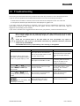
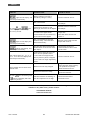
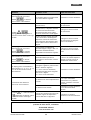
12 Troubleshooting ........................................................................... 21
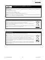
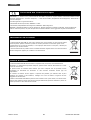
Conformity to the European Directives ................................................... 23
Product Disposal ............................................................................... 23
Lead Batteries ................................................................................. 23
Manuale Utente – Italiano .................................................................... 24
Avvisi di Sicurezza ............................................................................ 24
Page is loading ...

ENGLISH
UPS EVO DSP PLUS MM 1 User’s manual
User’s Manual - English
Safety Warnings
Read this manual carefully and completely before installing and using the TECNOWARE EVO DSP
PLUS MM Uninterruptible Power Supply, which, from here after, will also be referred to as UPS.
The UPS must be used only by properly trained personnel. To ensure correct and safe
operations, it is necessary that operators and maintenance personnel observe the general
safety Standards as well as the specific instructions included in this manual.
Risk of electric shock: do not remove the cover. The UPS contains internal parts which are at a
high Voltage and are potentially dangerous, capable of causing injury or death by electric
shock.
There are no internal parts in the UPS which are user serviceable. Any repair or maintenance
work must be performed exclusively by qualified technical personnel authorized by
TECNOWARE. TECNOWARE declines any responsibility if this warning is disregarded.
The electric installation has to be done by qualified personnel. Follow all the Safety Standards
(CEI Standards in Italy or IEEE elsewhere) for the Input/Output connections and for the right
section of Input/Output cables.
It is compulsory to ground the UPS according to Safety Standards.
Risk of electric shock at the Output lines when the UPS is ON.
Risk of electric shock at the Output lines while the unit is connected to the AC utility line.
For respect of the Safety Standards is necessary the presence of a differential circuit breaker
between UPS Output lines and the loads.
We recommend to use a dedicate AC power line for the UPS.
Do not obstruct ventilation slots or holes and do not rest any object on top of the UPS.
Do not insert objects or pour liquids in the ventilation holes.
Install the UPS indoors, in a protected, clean and moisture-free environment.
Do not expose to the direct sun light.
Do not keep liquids, flammable gases or corrosive substances near the UPS.

ENGLISH
User’s manual 2 UPS EVO DSP PLUS MM
1 Introduction
The UPS EVO DSP PLUS MM (UPS means Uninterruptible Power Supply) is the result of constant technological
research aimed at obtaining the best performance at the lowest cost.
EVO DSP PLUS MM is an advanced ON-LINE UPS built specifically to protect your computer from any irregularities in
the AC line (for example blackouts, brownouts, over voltages, micro-interruptions), which often cause damage to
hardware and software.
All that is possible because EVO DSP PLUS MM is a Double-Conversion ON-LINE UPS.
Under normal AC line condition EVO DSP PLUS MM provides an automatic Output Voltage regulation from the
Rectifier and Inverter blocks and filters out frequently occurring electrical disturbances (high Voltage transients,
spikes, interferences, etc.), thus protecting the devices connected to its outlets. During a power failure, EVO DSP
PLUS MM continues supplying adequate AC power (with a true sine wave) to all connected devices through its
internal batteries and by its DC/AC converter (Inverter).
EVO DSP PLUS MM protects the devices from accidental overload or Inverter fault by an Automatic Bypass that
directly connects the AC Input line with its outlets.
EVO DSP PLUS MM models are factory-equipped with RS-232 and USB interfaces, which may be used for notify to a
computer a power failure or a Low Battery condition: this allows automatic data backup during an extended
blackout with the most common operating systems (Windows, Linux, Unix, etc). Thanks to Interfaces, UPS DSP MM
can communicate the several made measurements (Input/Output Voltage, batteries, absorption, Frequency, etc.),
and can also be programmed in order to start-up or shutdown automatically at fixed times.
Read this manual carefully before using the EVO DSP PLUS MM; it includes important
safety warnings and useful advices for correct use and installation.
EVO DSP PLUS MM is constantly being developed and improved: consequently, your unit may differ somewhat from
the description contained in this manual.
This manual includes the following models:
• EVO DSP PLUS MM 1.2 (1.2 KVA)
• EVO DSP PLUS MM 2.4 (2.4 KVA)
• EVO DSP PLUS MM 3.6 (3.6 KVA)
In this manual EVO DSP PLUS MM will simply be referred to as UPS.
EVO DSP PLUS MM models are made from a single unit that contains the electronics parts and the batteries.

ENGLISH
UPS EVO DSP PLUS MM 3 User’s manual
2 General Characteristics
EVO DSP PLUS MM has all the advanced features which guarantee maximum reliability and safety:
• Double-Conversion ON-LINE Transformerless technology
• Sinusoidal wave generated by an IGBT Inverter
• Output Voltage regulation ±2%
• Protection from overload and short circuits
• Automatic Bypass to protect from accidental overload or Inverter fault
• Start-up even under Mains OFF conditions
• Automatic protection when Battery is low
• Automatic restart, following an automatic shut-down due to Low Battery, once AC utility power comes
back on
• Selectable Input Frequency (50 or 60 Hz)
• Graphic LCD panel for visualization of the Input and Output Voltage measurements, batteries Voltage,
percentage of load, frequency, alarms, overload, fault and path of energy flow
• Acoustic signals of various kinds indicating alarm situations
• Available settings of all the UPS parameters by user through front panel pushbuttons and graphic LCD
panel
• SNMP Adapter (optional)
• Communication with the computer through RS-232 and USB interfaces
• ECO functioning mode (selectable)
• Frequency Converter functioning mode (selectable)
• High efficiency
• Maximum reliability
• Smart design and easy to use
3 Receipt and site selection
Carefully remove the UPS from its packaging, and carry out a meticulous inspection. We recommend keeping the
original packaging in a secure place, in case you need to send the UPS for maintenance purposes. In case of
transport damage, notify the carrier and dealer immediately.
We recommend paying attention to the below points in order to choose a correct placement for your UPS:
• The UPS is designed to operate in a protected environment (e.g. offices). We therefore recommend
installing it in a place with very little or no humidity, dust or smoke.
• When the UPS is brought from a cold place to a warmer place, humidity in the air may cause condensation
in the UPS. In this case, allow UPS to stand for two hours in the warmer place before beginning with the
installation.

ENGLISH
User’s manual 4 UPS EVO DSP PLUS MM
• In all circumstances, see the “Technical Characteristics” chapter for environmental specifications and
check that the selected area meets these criteria.
• During normal operation the UPS discharges a minimal amount of heat. So it is necessary to leave at least
10 cm of unobstructed space all around the UPS in order to keep it properly ventilated.
• Do not obstruct ventilation holes.
• Do not insert objects or pour liquids in the ventilation holes.
• Do not rest any object on top of the UPS.
• Do not keep liquids, flammable gases or corrosive substances near the unit.
• Install the UPS on a properly tiled floor. Avoid the installation on a floor that is not tiled flat.
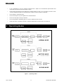
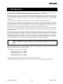
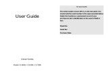
4 Operating Modes
Figure 1 – Operating modes
BATTERY MODE
NORMAL MODE
BYPASS MODE

ENGLISH
UPS EVO DSP PLUS MM 5 User’s manual
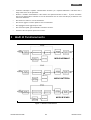
4.1 NORMAL Mode
The UPS typically works in Normal mode: Input mains power is available and its amplitude is within specifications.
Please refer to figure 1.
After the filter has eliminated any high Frequency interference present on the mains, the AC Input line is rectified
and conditioned in the Rectifier block (AC/DC conversion); the continuous power now enters into the Inverter
block and is then reconverted into alternated power (DC/AC conversion), overcoming the Automatic Bypass and
feeding the load after an extra filtration. At the same time the UPS recharges the batteries through the Battery
Charger block.
Please refer to figure 2, which describe the UPS front panel.
The Normal mode is identified by:
• The graphic LCD panel shows the path of energy flow
during Normal mode.
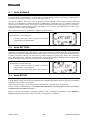
4.2 BATTERY Mode
During operation in Normal mode, if the UPS finds the Mains OFF condition (due to a Blackout or
Overvoltage/Brownout), it then switches into Battery mode. In this case, the batteries supply the required Output
power thanks to the DC/AC conversion carried out by the Inverter. The UPS switches back to Normal mode a few
seconds after AC Input power is restored or Voltage comes back to internal specifications.
Please refer to figure 1.
The Battery mode is identified by:
• The graphic LCD panel shows the path of energy flow
during Battery mode.
• An acoustic signal every 4 seconds.
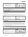
4.3 BYPASS Mode
In Bypass mode, the AC Input line is directly connected with the UPS outlets by an Automatic Bypass.
As indicated in figure 1, in Bypass mode the UPS recharges the batteries.
During Normal mode, the UPS switches automatically to Bypass mode as a consequence of accidental overload
or Inverter fault thus protecting the supplied devices.
When the UPS is working in Normal mode it is possible to switch the UPS by pressing continuously ON/MUTE and
SELECT buttons at the same time for at least 5 seconds, as explained into chapter 5.

ENGLISH
User’s manual 6 UPS EVO DSP PLUS MM
The Bypass mode is identified by:
• The graphic LCD panel shows the path of energy flow
during Bypass mode.
• An acoustic signal every 10 seconds.
During Bypass mode, loads are fed directly from AC Input line. Therefore some
protections against AC Input line disturbances or interruptions is present.
4.4 STAND-BY Mode
If the UPS is in Stand-by mode, it is “inactive”. In Stand-by mode the Inverter is off and there is not Output power
but the UPS is not completely off: indeed the UPS recharges the batteries regularly and the graphic display is ON.
If the OFF button is pressed when the UPS is in Normal mode, the UPS switches in Stand-by mode.
If the UPS is in Stand-by mode and the AC Input line is removed from UPS, then the UPS switches completely off.
The Stand-by mode is identified by:
• The graphic LCD panel shows the path of energy flow
during Stand-by mode.
4.5 ECO Mode
It is possible to select the ECO mode to save energy and to increase the efficiency of the UPS.
The ECO mode uses the Bypass to feed the loads. The UPS will operate as in Bypass mode whenever the
Frequency/waveform/RMS value of AC Input line mains Voltage is within their tolerance limits. If the AC Input line
Voltage goes beyond these limits, the UPS switches into normal operation.
Please contact Technical Service for the instruction to enable the ECO mode; by default the ECO mode is disable.
ECO mode does not provide perfect stability in Frequency/waveform/RMS value of the
Output Voltage like in Normal mode. Thus, the use of this mode should be carefully
executed according to the level of protection required by the application.
The ECO mode is identified by:
• The graphic LCD panel shows the path of energy flow
during ECO mode (the “ECO” icon is ON).

ENGLISH
UPS EVO DSP PLUS MM 7 User’s manual
4.6 CONVERTER FREQUENCY Mode
It is possible to select the Converter Frequency mode to work with the Output Frequency different from the Input
Frequency. For example it is possible to work with 60 Hz Input Frequency and 50 Hz Output Frequency or 50Hz
Input Frequency and 60 Hz Output Frequency.
Please contact Technical Service for the instruction to enable the Converter Frequency mode; by default
Converter Frequency mode is disable, and the Output Frequency will synchronize automatically with the Input
Frequency; by default the Converter Frequency mode is disable.
The Converter Frequency mode is identified by:
• The graphic LCD panel shows the path of energy flow
during Converter Frequency mode.
• The “CF” characters are ON.
5 EXTERNAL DESCRIPTION
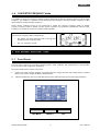
5.1 Front Panel
The front panel informs the user about operating status, alarm conditions and measurements. It also provides
access to controls and configuration parameters.
Front panel shown below consists of two parts:
1. Graphic LCD panel provides complete information about the energy flow path and existing alarms, Load and
Battery level, Input, Output and Battery measurements.
2. 3 buttons enables the user to turn ON/OFF the UPS and to make selections of the functioning parameters.
ON / MUTE
SELECT
OFF

ENGLISH
User’s manual 8 UPS EVO DSP PLUS MM
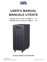
Figure 2 – Front panel
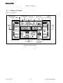
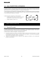
5.1.1 Graphic LCD Panel
Please refer to figure 3.
Figure 3 – Graphic LCD Panel
Battery
Info
Mode Operation
Info
Input & Battery
Voltage Info
Output
Voltage Info
Load
Info
Backup Time
Info
Fault Info Buzzer Info
Programmable
Output
Info

ENGLISH
UPS EVO DSP PLUS MM 9 User’s manual
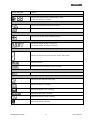
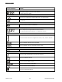
Graphic LCD Panel Function
Backup time information
Indicates how much time has passed in Battery mode.
H: hours, M: minutes, S: seconds
Fault information
Indicates the warning that a fault has occurred.
Indicates the Fault codes, and the codes are listed in the “Fault Table” of chapter
8.
Mute operation
Indicates that the UPS alarm is disabled (muted).
Output Voltage information
Indicates the Output Voltage or Frequency.
Vac: Output Voltage, Hz: Output Frequency
Load information
Indicates the load level by 0-25%, 26-50%, 51-75%, and 76-100%.
Indicates Overload.
Indicates the load or the Output is short-circuited.
Programmable Output information
Indicates that there is an active scheduling for the programmable Output.
Mode operation information
Indicates the UPS connects to the mains.
Indicates the Battery is working.
Indicates the Bypass circuit is working.
Indicates the ECO mode is enabled.
Indicates the Inverter circuit is working.
Indicates the Output is working.

ENGLISH
User’s manual 10 UPS EVO DSP PLUS MM
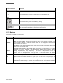
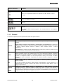
Graphic LCD Panel Function
Battery information
Indicates the Battery capacity by 0-25%, 26-50%, 51-75%, and 76-100%.
Indicates the Battery is faulty or defective.
Indicates Low Battery level and Low Battery Voltage.
Input and Battery Voltage information
Indicates the Input Voltage or Frequency or Battery Voltage.
Vac: Input Voltage, Vdc: Battery Voltage, Hz: Input Frequency
5.1.2 Buttons
Functions of the buttons are given below:
Button Function
ON/MUTE
Turn ON the UPS: press and hold ON/MUTE button for at least 3 seconds to turn ON the UPS.
Mute the acoustic alarm: when the UPS is in Battery mode, press and hold this button for at
least 5 seconds to disable or enable the acoustic alarm. But it’s not applied to the situations
when warnings or errors occur.
Test Battery: press and hold ON/MUTE button for at least 5 seconds to perform the Battery Test
while the UPS is in Normal mode.
SELECT
Select the measurements on the graphic display: by pressing the SELECT button it is possible
to choose the electrical parameter to be displayed (Input Voltage, Input Frequency, Battery
Voltage, Output Voltage, Output Frequency). If the button is not pressed for at least 10
seconds, then the default parameter will came back on the graphic display (the default
parameters are Input Voltage and Output Voltage).
OFF
Turn OFF the UPS: press and hold ON/MUTE button for at least 3 seconds to turn OFF the UPS.
By pressing this button while the UPS is in Normal mode, the UPS will go to Stand-by mode; by
pressing this button while the UPS is in Battery mode, the UPS will switch OFF completely.
ON/MUTE
+
SELECT
Switch to Bypass mode: when the UPS is functioning in Normal Mode, press ON/MUTE and
SELECT buttons simultaneously for at least 5 seconds. Then UPS will enter to Bypass mode. This
action will be ineffective when the Input voltage is out of the acceptable range.

ENGLISH
UPS EVO DSP PLUS MM 11 User’s manual
5.1.3 Acoustic Alarm
UPS status Acoustic Alarm OFF
Battery Mode Beeping once every 4 seconds YES
Low Battery Beeping once every second
NO
Overload Beeping twice every second
Fault Mode Beeping continuously
Bypass Mode Beeping once every 10 seconds
Note: OFF = YES : means that the buzzer can be muted or stopped, by pressing ON/MUTE button.
OFF = NO : means that the buzzer can NOT be muted or stopped
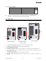
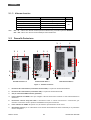
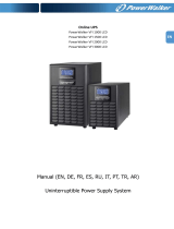
5.2 Rear Side
Figure 4 – Rear Side
1. Computer Interface (DB9 female connector): it is the communication RS-232 port.
2. Computer Interface (USB connector): it is the communication USB port.
3. Slot for SNMP Interface (optional)
4. Grounded AC Input power socket: to connect the UPS to the AC utility line by the included power cord.
5. Input Circuit Breaker: it goes off in Overload or short-circuit condition; push the external button of the
Circuit Breaker to reactivate it.
6. Grounded Output Receptacles: IEC C13 type; to supply critical loads.
7. Grounded Output Terminal Block: to connect an Output power line to supply all the devices to be
protected
1
2
4
EVO DSP PLUS MM 1.2
EVO DSP PLUS MM 2.4
3
4
2
1
3
5
5
6
6
2
1
3
6
5
4
7
EVO DSP PLUS MM 3.6

ENGLISH
User’s manual 12 UPS EVO DSP PLUS MM
5 Electrical Installation
The electrical installation has to be done by qualified personnel. Follow all the Safety
Standards (CEI Standards in Italy or IEEE elsewhere) for the Input/Output connections
and for the right selection of Input/Output cables.
For safety we recommend using external circuit breakers between Input mains and UPS
AC Input line and between UPS Output lines and the loads. The circuit breakers should
be qualified with leakage current protective function (leakage current < 30 mA).
For the Input/Output connections use ONLY the included power cables or cables with
the same power ratings.
TECNOWARE declines any responsibility if this warning is disregarded.
The EVO DSP PLUS MM models are made of a single unit design that contains the electronic parts and batteries.
Before starting the installation procedure, be sure that:
1. The AC Input Voltage for the UPS has been removed.
2. The UPS is completely OFF (only if graphic LCD panel is OFF).
6.1 Installation
We advise you to follow the steps below explained:
1. Through the included power cable connect the UPS Input socket to the AC line outlet (see figure 4). It is
mandatory to ground the AC line outlet according to the Safety Standards. Carefully check the grounding
of AC line outlet.
2. Connect the devices to be supplied to the UPS outputs, by using only the included cables. Be sure all the
devices have the main switch in OFF position.

ENGLISH
UPS EVO DSP PLUS MM 13 User’s manual
It is compulsory to ground the UPS according to the Safety Standards.
The case of the UPS is internally connected to the ground terminal (GND) of the IN/OUT
terminals, in order to guarantee safety to the user. To guarantee safety it is necessary
to be sure that the local electric plant is supplied with GROUND (in compliance with the
Safety Standards), and that a valid connection is guaranteed between the GROUND of
the UPS and the GROUND of the local electric plant.
Any interruption of the GROUND conductor is absolutely prohibited.
Risk of electric shock at the Output lines if the UPS is ON, even when the UPS is not
connected to AC utility line.
Risk of electric shock at the Output lines while the unit is connected to the AC utility
line.
Risk of electric shock: do not remove the cover. The UPS contains internal parts which
are at a high Voltage and are potentially dangerous, capable of causing injury or death
by electric shock.
There are no internal parts in the UPS which are user serviceable. Any repair or
maintenance work must be performed exclusively by qualified technical personnel
authorized by TECNOWARE. TECNOWARE declines any responsibility if this warning is
disregarded.
Disregard for these warnings may lead to a risk of electric shock to operators.
7 First Start Up
Turning the UPS ON is very easy. Nevertheless we recommend that, on First Start Up, the following procedure is
observed for greater safety.
1. Be sure all the devices connected to the UPS outputs have the main switch in OFF position.
2. Restore the AC Input line for the UPS; be sure that the AC utility power is available, and that its voltage and
frequency are within the specifications.
3. As a consequence of point 2, the UPS turns on the graphic display and goes in Stand-by mode: the UPS
recharges only the batteries and doesn’t supply Output power. Check the graphic display shows the path of
energy flow during Stand-by mode.
4. Press ON/MUTE button for at least 3 seconds: the UPS emits a brief acoustic signal and performs a
functioning SELF-TEST. After some seconds the UPS starts to work in Normal Mode and the graphic LCD
panel will show the path of energy during Normal mode.
5. Simulate a black-out by removing the AC Input line. The UPS starts working in Battery mode: the graphic LCD
panel will show the path of energy during Battery mode. Moreover UPS emits a brief acoustic signal every 4
seconds. When Battery level is ending the acoustic signal will be emitted every 1 second.
6. Restore the AC Input line: after few seconds the UPS turns back in Normal mode.
7. The UPS has passed first start up check: now turn ON the devices (one by one) to be supplied by UPS,
checking the UPS doesn’t report Overload information on the graphic LCD panel and all the devices are
working regularly. By graphic display check if the Output load percentage is less than 100%; otherwise it is
necessary to remove part of the loads at the Output lines.
Before using the UPS normally, leave it in Normal mode for in order to charge Battery completely (the UPS charges
Battery also in Bypass mode or in Stand-by Mode). The batteries reach the 90% of their capacity after about 4
hours of recharge.

ENGLISH
User’s manual 14 UPS EVO DSP PLUS MM
8 Functioning
8.1 Turning ON and OFF
Let’s see carefully the consequences of the pressure of ON/MUTE and OFF buttons.
The UPS is in Stand-by mode (the Inverter is OFF); if the ON/MUTE button is pressed, after few seconds the
Inverter starts and the UPS switches in Normal mode.
The UPS is in Normal mode (the Inverter is ON); if the OFF button is pressed, the Inverter turns OFF and the UPS
switches in Stand-by mode.
To turn completely OFF the UPS please do the following steps:
Put the UPS in Stand-by mode by pressing the OFF button
Disconnect the AC Input Voltage for the UPS.
The graphic LCD panel is OFF only when the UPS is completely OFF.
If UPS is used daily, it is recommended to leave the UPS connected to the AC Input line and use the ON/MUTE and
OFF buttons on the front panel to activate/deactivate the Inverter.
If the UPS has to be turn OFF completely for several days, it is recommended to disconnect the AC Input line for
the UPS and then press the OFF button.
If the ON button is pressed when AC Input line is not present, the UPS switches ON even, and works in Battery
mode after some seconds.
If the OFF button is pressed when AC Input line is not present, then the Inverter switches OFF and consequently
there will be no Output power.
8.2 Low Battery and Automatic Restart
The UPS reaches the Low Battery condition whenever, during working in Battery mode, the batteries reach a
charge level allowing the connected devices to operate for few minutes more.
The UPS warns operators of Low Battery by lighting of the LOW BATT. icon on the graphic LCD and by emitting an
acoustic signal every second.
If AC Input does not come back on within few minutes, the UPS shuts-down automatically thus preventing the
batteries from discharging excessively; the UPS stops supplying Output power, deactivates control panel indication
and goes to a waiting state. Once AC Input comes back on, the UPS restarts automatically and after 4 seconds it
goes back to work in Normal mode.
After a complete discharge, the UPS needs 4 hours to recharge completely the batteries. The UPS recharges
batteries automatically if it works in Normal mode, in Bypass mode or in Stand-By mode.

ENGLISH
UPS EVO DSP PLUS MM 15 User’s manual
8.3 Load Testing
The UPS indicates the Output Load level by graphic LCD (on the right side as described in the chapter 5).
When the Output load is higher then nominal value the UPS warns of Overload condition by graphic LCD and by
acoustic alarm as described in the “Warning Table” and in the “Troubleshooting” chapter.
The UPS warns of an Overload less than 110% by acoustic alarm.
An Overload between 110% and 130% is accepted for about 30 seconds and after UPS switches automatically to the
Bypass mode.
The UPS switches immediately to the Bypass mode if the Overload is higher than than 130%.
Once the requested power is back within range, the UPS switches automatically to the Normal mode.
Make sure that the UPS never indicates Overload condition.
Do not connect a load greater than rated value to the UPS (see POWER specifications in
the chapter “Technical Characteristics”), as this may damage the unit. In this case the
warranty is void.
8.4 Static Bypass
During Normal mode functioning it is possible to switch the UPS in Bypass mode, by pressing at the same time
ON/MUTE and SELECT buttons at least 5 seconds, as explained into chapter 5.
The Bypass mode, named also Static Bypass, is useful while performing maintenance or service on the UPS.
The Static Bypass, used together with an external Manual Bypass device, enables the user to isolate the electronic
circuitry of the UPS from the mains and from the load, and to remove the UPS without interrupting the power by
connecting the load directly to the mains.
Maintenance and service may only be performed by authorized technical personnel.
During Static Bypass, loads are fed directly from Bypass mains. Therefore some
protections against AC Input line disturbances or interruptions is present.

ENGLISH
User’s manual 16 UPS EVO DSP PLUS MM
8.5 Battery Test
It is possible to check the Battery Status when the UPS is running in Normal mode/Converter Frequency mode/ECO
mode, by performing a Battery Test.
To perform the Battery Test, press the ON/MUTE button continuously for at least 5 seconds. The Battery Test
starts immediately and it finishes after some seconds. If the batteries pass the test, no alarm will be shown.
During the Battery Test, the graphic LCD and buzzer indication will be the same as at Battery mode.
To keep the system reliable, the UPS will perform the Battery Test automatically once per week.
User also can set Battery Test through monitoring software.
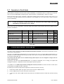
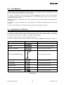
8.6 Operation in Warning Status
During a warning condition the buzzer beeps once every second, it means that there are some problems for UPS
operation. Users can get the Fault code from graphic LCD panel. Please check the “Troubleshooting” chapter for
details.
Below you can see the “Warning Table”, with the correspondence between each warning and the relative signals
(icons on graphic LCD and acoustic alarm) for the user.
Some acoustic alarms can’t be muted unless the error is fixed. Please refer to chapter 5 for the details.
WARNING ICON (flashing) ACOUSTIC ALARM
Low Battery
Beeping every second
Overload
Beeping twice every second
Battery Unconnected
Beeping every second
Over Charge
Beeping every second
Reversed phase for AC Input Line
Beeping every second
Fan failure/Over temperature
Beeping every second
Over temperature
Beeping every second
Battery Charger failure
Beeping every second
Bypass Voltage out of range
Beeping every second
Warning Table

ENGLISH
UPS EVO DSP PLUS MM 17 User’s manual
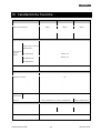
8.7 Operation in Fault Mode
When Fault led illuminates and the buzzer beeps continuously, it means that there is a fatal error in the UPS.
Users can get the Fault code from display panel. Please check the “Troubleshooting” chapter for details.
Please check the loads, wiring, ventilation, mains supply, Battery and so on after the fault occurs. Don’t try to
turn ON the UPS again before solving the problems. If the problems can’t be fixed, please contact Technical
Service immediately.
In case of emergency, please disconnect the connection from mains supply and Output
immediately to avoid further risk or danger.
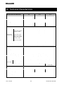
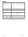
Below you can see the “Fault Table”, with each Fault event and the relative FAULT code/icon on graphic LCD for
the user’s information.
FAULT EVENT FAULT CODE
ICON FAULT EVENT FAULT CODE
ICON
Vdc Bus Start failure 01 None Inverter Output short-circuit 14
Vdc Bus Over 02 None Battery Voltage too High 27
Vdc Bus Under 03 None Battery Voltage too Low 28
Vdc Bus Unbalance 04 None Over Temperature 41 None
Inverter Soft Start failure 11 None Overload 43
High Inverter Voltage 12 None Charger failure 45 x
Low Inverter Voltage 13 None
Fault Table
9 Communication Interfaces
The UPS is factory-equipped with RS232 and USB Communication Interfaces. On the UPS rear side there are the
connections of the Interfaces.
Only one of the RS232/USB communications can be activated at one time. To activate RS232 communication it is
sufficient to connect the RS232 cable only (9 pins cable, pin to pin); to activate USB communication it is sufficient
to connect the USB cable only.
The RS-232 and USB signals are all isolated through photo-couplers from the dangerous voltages that are
present inside the UPS.
Connecting to the Web site www.tecnoware.com, it is possible to download, free of charge, the update UPS
management Software, compatible with the most popular Operative Systems.
It is possible to use a SNMP (Single Network Management Protocol) Interface to connect the UPS to a LAN (Local
Area Network). The SNMP interface is optional.
We advise you to follow the steps below explained to install the interface correctly:
1. Remove the metallic panel (#3, figure 4) that covers the slot for SNMP interface.
2. Put the SNMP Interface into the slot and fix it with screws.
3. Connect the LAN cable to SNMP interface and follow the included instruction to make the interface working
well.

ENGLISH
User’s manual 18 UPS EVO DSP PLUS MM
10 Technical Characteristics
UPS EVO DSP PLUS MM Model 1.2 2.4 3.6
Power 1200 VA 2400 VA 3600 VA
Nominal Active Power 840 W 1680 W 2520 W
Power Factor 0.7
Technology On-Line Double Conversion Transformerless
Dimension (W x H x D) 14,5 x 22 x 28,2 cm 14,5 x 22 x 39,7 cm 19 x 31,8 x 42,1 cm
Net Weight 10 kg 17 kg 27
INPUT
Nominal Voltage Single Phase 200/208/220/230/240 Vac
Voltage Range
for Normal mode
Lower Limit (transfer
to Battery mode)
110 Vac ± 5% (at 0-60% load)
120 Vac ± 5% (at 60-70% load)
140 Vac ± 5% (at 70-80% load)
160 Vac ± 5% (at 80-100% load)
Lower Limit (come
back to Line mode)
175 Vac ± 5%
Upper Limit (transfer
to Battery mode)
300 Vac ± 5%
Upper Limit (come
back to Line mode)
290 Vac ± 5%
Nominal Frequency 50/60 Hz (automatic selection)
Frequency Range (Normal mode) 47 ~ 53 Hz / 57 ~ 63 Hz
Input Power Factor 0.99 (at 100% Load)
OUTPUT
Nominal Voltage Single Phase 200/208/220/230/240 Vac (selectable)
Voltage Regulation ±2%
Inverter Waveform True Sinewave
Nominal Frequency 50/60 Hz (selectable)
Free Running Frequency (Battery mode) (50 Hz ± 0.25%) or (60 Hz ± 0.25%)
Total Harmonic Distortion (THD) < 3% (Linear Load); < 6% (Non-Linear Load)
Crest Factor 3:1 max
Overload (100÷110)% only acoustic alarm ; (110÷130)% for 30 sec; > 130% per 100 ms
Transfer Time
(Normal <--> Battery) 0 ms
(Battery <--> Bypass) 4 ms (typical)
Efficiency 92% (On-Line mode) ; 98% (ECO mode)
93% (On-Line mode) ; 98%
(ECO mode)
BATTERIES
Battery Type Lead acid, sealed, free maintenance
Number of batteries 2 4 6
Nominal Battery Voltage 24 Vdc 48 Vdc 72 Vdc
Battery Specifications 12 Vdc – 9 Ah
Backup Time (typical) 8 min
Battery Charge Time (typical) 4 hours
Page is loading ...
Page is loading ...
Page is loading ...
Page is loading ...
Page is loading ...
Page is loading ...
Page is loading ...
Page is loading ...
Page is loading ...
Page is loading ...
Page is loading ...
Page is loading ...
Page is loading ...
Page is loading ...
Page is loading ...
Page is loading ...
Page is loading ...
Page is loading ...
Page is loading ...
Page is loading ...
Page is loading ...
Page is loading ...
Page is loading ...
Page is loading ...
Page is loading ...
Page is loading ...
Page is loading ...
Page is loading ...
Page is loading ...
Page is loading ...
Page is loading ...
Page is loading ...
-
 1
1
-
 2
2
-
 3
3
-
 4
4
-
 5
5
-
 6
6
-
 7
7
-
 8
8
-
 9
9
-
 10
10
-
 11
11
-
 12
12
-
 13
13
-
 14
14
-
 15
15
-
 16
16
-
 17
17
-
 18
18
-
 19
19
-
 20
20
-
 21
21
-
 22
22
-
 23
23
-
 24
24
-
 25
25
-
 26
26
-
 27
27
-
 28
28
-
 29
29
-
 30
30
-
 31
31
-
 32
32
-
 33
33
-
 34
34
-
 35
35
-
 36
36
-
 37
37
-
 38
38
-
 39
39
-
 40
40
-
 41
41
-
 42
42
-
 43
43
-
 44
44
-
 45
45
-
 46
46
-
 47
47
-
 48
48
-
 49
49
-
 50
50
-
 51
51
-
 52
52
-
 53
53
-
 54
54


Tecnoware EVO DSP PLUS 1.2 MM User manual
- Type
- User manual
- This manual is also suitable for
Ask a question and I''ll find the answer in the document
Finding information in a document is now easier with AI
in other languages
Related papers
-
Tecnoware EVO DSP PLUS MM 3.6 User manual
-
-
-
-
-
-
 TECHNOWARE ERA LED 1.5 User manual
-
-
-
Tecnoware UPS ERA LCD 2.6 Specification

Other documents
-
Ewent EW3943 Specification
-
 OPTI-UPS DS1000D User manual
-
Riello DVR 1100 User manual
-
 TECHWARE ERA LCD 0.65 Rack Mount User manual
-
Riello DVD 150 User manual
-
 OPTI-UPS CS385B User manual
-
Atlantis A03-OP1002XLN User manual
-
 Siel Green Point 6:20KVA User manual
-
-
 PowerWalker VFI 1500 LCD Owner's manual


