Page is loading ...

ISSUED: 07-24-12 SHEET #: 180-9023-1
User Manual and Installation Guide
Pro Wireless Multimedia Kit
Models:
HDS200
HDS200-2
HDS200-3
HDS200-4
READY
®


3 of 36
ISSUED: 07-24-12 SHEET #: 180-9023-1
Contents
Safety Precautions ...........................................................................................................................................4
Proper Care and Safety ....................................................................................................................................4
Unit Care Recommendations ..........................................................................................................................4
Introduction .......................................................................................................................................................5
Features .........................................................................................................................................................5
Package Contents ..........................................................................................................................................5
Product Specifi cations.....................................................................................................................................6
Video Format Supported ................................................................................................................................7
Audio Format Supported ................................................................................................................................7
Wireless Connection ......................................................................................................................................7
WiFi Channel Frequencies .............................................................................................................................7
Transmitter .....................................................................................................................................................8
Receiver .......................................................................................................................................................12
Remote Control ............................................................................................................................................16
Installation and Operation .............................................................................................................................19
Selecting Input and Output Port ..................................................................................................................23
Peer-to-Peer and Multicast LAN (wired) Mode Installation ..........................................................................23
Peer-to-Peer Direct LAN Connection ...........................................................................................................23
LAN Connection Through Router (LAN One-to-One) ...................................................................................24
Confi guring for LAN Through Router (LAN One-to-One) .............................................................................24
Indicator Lights Decoded ..............................................................................................................................25
IR Flasher .....................................................................................................................................................26
IR Extender ..................................................................................................................................................26
Product Modes .............................................................................................................................................26
Peer-To-Peer Modes ....................................................................................................................................26
Multicast Modes ...........................................................................................................................................27
LAN - Wired Connection Mode .....................................................................................................................27
FAQs ................................................................................................................................................................28
Appendix .........................................................................................................................................................30
Warranty ..........................................................................................................................................................34
Contact Information .......................................................................................................................................35

4 of 36
ISSUED: 07-24-12 SHEET #: 180-9023-1
Please read this manual before using the product.
• Unit can be placed vertically (preferred) or horizontally.
• To clean, use a soft, dry cloth only. Do not use water or other cleaning products as they
may cause electrical failure or damage the surface of the product.
Keep the product out of reach of
children.
Keep the product away from external
heat sources such as heaters or
stoves.
If there is any unusual sound, smoke
or odor coming from the product,
immediately unplug the product and
call Peerless-AV Customer Care at
1-800-865-2112.
Keep the battery of remote control out
of reach of children.
Do not attempt to open the outer case
of the Transmitter or Receiver. Doing
so will void the product warranty.
Keep the remote control away from
humidity and/or liquids.
Do not insert foreign objects into the
unit.
Do not place the unit on an unstable
surface or in a poorly ventilated area.
Make sure to plug the AC power
adapters fi rmly into wall outlets.
Do not use the unit near any fl ammable
substances or combustible sprays.
Proper Care and Safety
Unit Care Recommendations
Safety Precautions
If any part of the AC power adapter
looks damaged, do not use the product
and immediately call Peerless-AV
Customer Care at 1-800-865-2112.
Keep the product unplugged if unused
for an extended period of time.

5 of 36
ISSUED: 07-24-12 SHEET #: 180-9023-1
HD Flow Pro Wireless Multimedia Kit provides Full HD 1080p signal transfer, including 3D signal*, without the
hassle of running cables. Create brilliant HD quality multimedia for signage, presentations, or entertainment in
any location,completely un-tethered to your source device!
By simply connecting the Transmitter to a multimedia device such as a computer, set-top box, or Blu-ray™
player and connecting the Receiver to a display device, instant real-time high defi nition digital audio and video
can be placed into in any commercial or residential setting. HD Flow Pro Wireless Multimedia Kit transmits
through walls and fl oors to allow the components to be neatly tucked away in an AV rack or media cabinet,
and is the ideal solution for quick and easy installation where running cable is cost prohibitive or simply not an
option.
* Works with passive 3D signals
Features
• Low latency: ≤ 30ms.
• Supports both digital (HDMI) and analog (Component, Composite) video/audio.
• Supports Wireless or Wired connection - IEEE 802.11n 5 GHz WiFi, LAN connection.
• Two internal antennas (supporting MIMO).
• HDCP v1.1 compliant.
• Supports both DTV & VESA standards: DTV: 1920x1080i60/p60, 1280x720p60, 720x480i60/p60,
VESA : WSXGA+(1680x1050), SXGA(1280x1024), WXGA(1280x800), XGA(1024x768),
SVGA(800x600), VGA(640x480).
• Supports passive 3D content.
• Plug and play setup requires no software programming.
Package Contents
Ensure that the following items are present in the package. If any items are missing or damaged, please call
Peerless-AV Customer Care at 1-800-865-2112 (available 7:00am - 7:00pm CST Monday - Friday).
Transmitter Remote ControlReceiver
IR-Flasher
Component
Adapter
Battery Manual
Stand (2)
Quick Start Guide
AC Adapter (2)IR-Extender
Introduction
Step 7 While turning on the display device the HD Flow Pro Wireless Multimedia units will be going through the startup process. This process may
take up to two minutes to complete. The Power/Link indicator lights on the Transmitter and the Receiver will be flashing at first. Flashing indicates
that the units are establishing a secure connection. Wait until the connection is successfully established, indicated by the Power/Link indicator
light becoming solid.
Minutes
2
1 x Transmitter
1 x Receiver
2 x Stand
1 x Remote Control
1 x IR Flasher
1 x IR Extender
1 x Component Adaptor
2 x Power Adapter
1 x Quick Start Guide
1 x Users Manual
Step 2 Connect the provided IR Flasher to the IR-OUT port on the Transmitter.
Find the location of the IR window on your component device and adhere the
IR Flasher eye directly over the IR window on your component device.
NOTE: One IR Flasher eye is to be used for one component device.
Step 4 I rovided IR Extender in to
the IR-IN port on the Receiver and adhering the other end of the IR Extender
to a vertical surface near the output device. Ensure that the IR Extender is in
a line of sight to the remote control that controls your source devices.
NOTE: For Multicast models, receivers two, three and four do not come with an IR Extender. Additional IR Extenders
(HDS-IRE) can be purchased separately; visit peerless-av.com for more information.
Step 6 Turn on your display device (TV, monitor, projector, etc.).
Step 3
to the Receiver.
S
1. Plug in the power adapter for the Transmitter and the Receiver to nearby
available power outlets.
2. Plug in the power adapter end to the Transmitter and then to the Receiver.
3. The units will automatically turn-on. The average power-on/sync time
is approximately two minutes.
What’s in the Box
Installation and Setup
Troubleshooting Tips
Tip The IR window
may be easier to
locate with a direct
light shining on
sections of the
front panel of the
component device.
A small flashlight
works well.
Power/Source
Selection Button
Tip RepeatSteps
3-11 to
more t
Receiv
(HDS20
HDS20
HDS20
Step 1 Connect the Transmitter to the source devices
(Blu-ray
™
Disc player, set top box, gaming console, etc.).
Step 9 Turn on the desired source device that is connected to
the Transmitter.
Step 11 Play the source device content and enjoy up to Full HD 1080p
wireless entertainment experience.
t Check the media source resolution. The display device must be able
to support the resolution of the media source that is being streamed.
Utilizing the INFO button will allow you to see the resolution data that
the dis
play device supports. If the display device supports the highest
resolution of 720p but the source device is outputting 1080p content,
the content needs to be down-scaled to the maximum resolution of the
display device, in this case 720p.
Receiver Output Indicator Light Blinks:
t Make sure that your display device, source device and the HD Flow Pro units
are all turned ON and the Receiver is properly connected to the output device.
t Verify that the Receiver is set to the appropriate output port.
t Check the resolution setting of your source device. This may need to be
changed to a resolution supported by the HD Flow Pro unit. Reference
the Resolution Chart in the HD Flow Pro Manual for compatibility.
Reference your source devices’ manual for instruction on changing
the output resolution.
If the above troubleshooting tips do not resolve the issues for a unicast setup,
please reference the Factory Reset Section of the HD Flow Pro Manual. For a
multicast system configuration, please contact Peerless-AV Customer Care at
800-856-2112 for further instruction.
Step 8 Select the output that connects the Receiver to the display using
the Power/Source Selection Button or the provided remote control.
The output indicator light will become solid and the HD Flow logo will
appear on the display device.
Step 10 Select the desired source or device input on the Transmitter
using the Power/Source Selection Button on the remote control.
Transmitter and/or Receiver Indicator Lights are all Blinking:
t The HD Flow Pro units are establishing a connection. It can take
up to two minutes for the HD Flow Pro units to establish a complete
connection. If after two minutes have passed and the units have not
established a connection, unplug the power cable, wait 30 seconds
and reconnect the power supply to the units.
Transmitter or Receiver Power Indicator Light is OFF:
t Check and verify the power supply connection.
Transmitter Input Indicator Light Blinks:
t Make sure that your source device is turned ON and the cable
is properly connected.
t Verify that the Transmitter is set to the appropriate input port.
t Check the resolution from your source device. This may need to
be changed to a resolution supported by the HD Flow Pro Wireless
Multimedia Kit. Reference the Resolution Chart in the HD Flow
Manual for compatibility. Reference your source devices’ manual
for instruction on changing the output resolution.
Receiver Power Indicator Light Blinks:
t Verify that the HD Flow Pro Transmitter and Receiver are within
the recommended range of 131 feet. Physical obstructions such as
walls, floors and ceilings between the Transmitter and Receiver may
decrease the strength of the connection signal and reduce the overall
transmission range.
If a connection has been established and the HD Flow logo can be seen
on the display device, but content is not playing:
t Make sure that the input/output cables are properly connected.
t Verify that the Transmitter is set to the appropriate input port.
Warning Do not place the HD Flow
Pro units near other devices that
emit excessive amounts of heat.
Increased temperatures may
cause the HD Flow Pro Transmitter
or Receiver unit to malfunction
or stop working.
t
e
p
s
Quick Start Guide for HD Flow Pro Wireless Multimedia Kit - LIT-0906
Power/Source
Selection Button
© 2012 Peerless Industries, Inc. Peerless-AV™ is a trademark of Peerless Industries, Inc. All rights reserved.
HD Flow™ is a trademark of I Do It, LTD. Other parties’ marks are the property of their respective owner s. hdflow.com
Quick Start Guide
PRO WIRELESS MULTIMEDIA KIT
Model No. HDS200 (-2, -3, -4)
READY
®
ISSUED: 06-12-12 SHEET #: 180-9023-1
User Manual and Installation Guide
Pro Wireless Multimedia Kit
Models:
HDS200
HDS200-2
HDS200-3
HDS200-4
READY
®

6 of 36
ISSUED: 07-24-12 SHEET #: 180-9023-1
2 x HDMI up to 1080p (60Hz)
1 x Composite
1 x YPbPr Component
1 x HDMI up to 1080p (60Hz)
1 x Composite
1 x YPbPr Component
H.264 Baseline Profile with Level 4.2
HDCP compliant
Wireless Connection
Supporting IEEE 802.11n: OFDM
RJ-45 LAN Port
Direct Connection (LAN Cable)
1 x LAN Port (Transmitter and Receiver)
10/100 Base
USB
1 x USB Type A Female (Receiver)
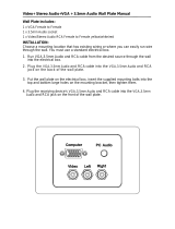
Audio Input
1 x 3.5mm Audio Jack, 1 Stereo RCA Audio Jack (Transmitter)
Audio Output
1 x 3.5mm Audio Jack, 1 Stereo RCA Audio Jack (Receiver)
Video Resolution
480i/p, 720p, 1080i/p (24/30/60fps)
Streaming Latency
< 30ms
Frequency
5.15 - 5.25GHz
LAN Connection
10/100 Base
Range
131ft (40m) maxium
Broadcast
1 Transmitter up to 4 Receivers*
Security
802.1x, 802.11i, WPA2, WPA and WEP 64/128 TKIP AES
2 x Internal Antenna (Transmitter and Receiver)
MIMO Interface
IR Flasher
3 IR Flashers
IR Extender
IR-Extender
Color
Black
Voltage: 12VDC
Amps: 2A
Consumption: 12V 2A
Antenna Type
Power
HDS200 Models
*Requires additional Receiver units
Video Input (Transmitter)
Video Output (Receiver)
Encoding
Wired Connection
LAN
Product Specifi cations

7 of 36
ISSUED: 07-24-12 SHEET #: 180-9023-1
Video Format Supported
• Digital Video
º HDMI - Up to 1080p @ 24Hz, 25Hz, 30Hz, 50Hz, 60Hz
• Analog Video
º Composite – 480i @ 60Hz, 70Hz, 85Hz
º Component – 1080i @ 50Hz, 60Hz, 720p @ 50Hz, 60Hz
º VGA – Up to 1920x1080 @ 50Hz, 60Hz
Audio Format Supported
• Analog
• Digital
• Receiver outputs stereo audio
Wireless Connection
• Peer-to-Peer Mode
• Multicast Wireless Mode
WiFi Channel Frequencies
• Channel 1: 5.19GHz (WiFi Ch 38)
• Channel 2: 5.23GHz (WiFi Ch 46)
Note: WiFi Channels are only active when using Wireless Peer-to-Peer or Multicast modes. The Transmitter
and Receiver have the ability to operate on two WiFi Channels. The default channel is Channel 1, if there is
interference issues on Channel 1 a change to Channel 2 will eliminate most of these issues.

8 of 36
ISSUED: 07-24-12 SHEET #: 180-9023-1
Transmitter Front
1
2
3
4
5
6
7
Transmitter

9 of 36
ISSUED: 07-24-12 SHEET #: 180-9023-1
Transmitter Front
1. Power/Link Indicator Light
• Blinking indicator light - System booting or establishing link between the Transmitter and the Receiver.
• Quick blinking indicator light - Software upgrading or wireless/LAN mode switching.
• Solid indicator light - Link between the Transmitter and Receiver has been established and is ready for
signal transmission.
2. HDMI 1
• The HDMI 1 indicator light will be illuminated when the HDMI 1 port is selected for video input.
• If there is no signal, and/or the cable is not connected, the indicator light will blink.
3. HDMI 2
• The HDMI 2 indicator light will be illuminated when the HDMI2 port is selected for video input.
• If there is no signal, and/or the cable is not connected, the indicator light will blink.
4. PC
• The PC indicator light will be illuminated when the PC In port is selected for video input.
• If there is no signal, and/or the cable is not connected, the indicator light will blink.
5. AV
• The AV indicator light will be illuminated when the AV In port (Composite) is selected for the video input.
• If there is no signal, and/or the cable is not connected, the indicator light will blink.
6. IR Window
• IR receiving window enables remote control of components.
7. Power/Source Selection Button
• Press and hold for 3 seconds to turn on the unit.
• When powered on:
º Press to select the video input source. Each press of the button will cycle through the available
video input "HDMI1→ HDMI2→ PC→ AV →HDMI1" in sequence.
º Press and hold for 8 seconds to turn the unit off.

10 of 36
ISSUED: 07-24-12 SHEET #: 180-9023-1
2
Transmitter Back
1
3
4
5
6
7
8

11 of 36
ISSUED: 07-24-12 SHEET #: 180-9023-1
Transmitter Back
1. HDMI 1 IN
• HDMI1 input port
2. HDMI 2 IN
• HDMI2 input port
3. AV-IN
• Composite input port
4. IR-OUT
• Connects IR Flasher to the Transmitter for remote control of external devices which are connected to the
Transmitter (i.e. Blu-Ray player, DVD, STB, etc).
5. PC AUDIO-IN *
• Stereo audio input port
6. PC-IN (VGA)**
• Supports component input with included Component Adaptor
7. LAN
• LAN connection is used for the following:
º Direct connection to LAN cable for LAN installations.
º Direct connection to PC for system confi guration settings.
8. DC
• DC power input
* For the audio part of a component media source, use the PC Audio input port with a 3.5mm to RCA cable
(not included).
** If using the PC Video input port for component (YPbPr) media source, use the included component to VGA
adapter.

12 of 36
ISSUED: 07-24-12 SHEET #: 180-9023-1
1
2
3
4
5
6
Receiver Front
Receiver

13 of 36
ISSUED: 07-24-12 SHEET #: 180-9023-1
Receiver Front
1. Power/Link
• Blinking indicator light - System booting or establishing link between the Transmitter and the Receiver.
• Rapid blinking indicator light - Software upgrading or wireless/LAN mode switching.
• Solid indicator light - Link between the Transmitter and Receiver has been established and is ready for
signal transmission.
2. HDMI
• The HDMI indicator light will be illuminated when the HDMI port is selected for video output.
• If there is no signal, and/or the cable is not connected, the indicator light will blink.
3. COMPO
• The COMPO (component) indicator light will be illuminated when component output is selected for video
output.
• If there is no signal, and/or the cable is not connected, the indicator light will blink.
4. AV
• The AV indicator light will be illuminated when the AV port (composite) is selected for the video output.
• If there is no signal, and/or the cable is not connected, the indicator light will blink.
5. IR Window
• IR receiving window enables remote control of components.
6. Power/Source Selection Button
• Press and hold for 3 seconds to turn on the unit.
• When powered on:
º Press to select the video input source. Each press of the button will cycle through the available
video input "HDMI→ COMPO→ AV →HDMI" in sequence.
º Press and hold for 8 seconds to turn the unit off.

14 of 36
ISSUED: 07-24-12 SHEET #: 180-9023-1
1
2
3
4
5
6
7
8
Receiver Back

15 of 36
ISSUED: 07-24-12 SHEET #: 180-9023-1
Receiver Back
1. HDMI-OUT
• HDMI output port
2. AV-OUT
• Composite output port
3. IR-IN
• Connects the IR Extender in order to extend IR reception range.
4. AUDIO-OUT*
• Stereo audio output port
5. COMPONENT-OUT*
6. USB
• USB port is used for fi rmware upgrades only.
7. LAN
• LAN connection port is used for the following:
º Direct connection for LAN installations.
º Direct connection to PC for system confi guration settings.
8. DC
• DC power input
* For the audio part of a component media source, use the PC Audio Input port with a 3.5mm-to-RCA cable
(not included).

16 of 36
ISSUED: 07-24-12 SHEET #: 180-9023-1
1
4
3
6
7
2
5
8
1. POWER Button - Turns the Transmitter and Receiver power ON/OFF.
• ON: If the Transmitter and Receiver are powered off and the Power/Link Indicator Light is on, press
the power button pointed at either unit to turn on both unit's at the same time (this will take about 30
seconds).
• ON: If the Transmitter and Receiver are powered off and the Power/Link Indicator Light is off, each unit
will need to be turned on separately. Point the remote at each unit's IR Input port and press the power
button to turn on (this will take about 1 minute and 30 seconds).
• OFF: If the Transmitter and Receiver are powered on and the Power/Link Indicator Light is on, press the
power button to turn off both units at the same time to put the system in Standby mode. The Power/Link
Indicator Light will remain on.
• OFF: If the Transmitter and Receiver are powered on and the Power/Link Indicator Light is on, press
and hold the power button for 8 seconds. Both Transmitter and Receiver will be turned off at the same
time. The Power/Link Indicator Light will turn off.
Note: If the Transmitter and Receiver are powered on with the Power/Link Indicator Light fl ashing, both units
will need to be powered off individually.
2. INFO* - Displays the following information on the screen for:
• Transmitter ** - WiFi Channel, Firmware Version, Audio/Video Input, and Source Resolution.
• Receiver - Connection, Firmware Version, Video Output, Display Resolution, WiFi Reception Strength
1/5 to 5/5 (where 1/5 is the weakest signal and 5/5 is the strongest signal).
* Displayed information will disappear automatically after 10 seconds.
** The Transmitter unit’s information will only be displayed if the connection between the Transmitter unit and
Receiver has been established.
Remote Control

17 of 36
ISSUED: 07-24-12 SHEET #: 180-9023-1
3. VIDEO OUT (Receiver) - Selects the Audio/Video output port of the Receiver.
• HDMI - Selects HDMI as the Audio/Video output.
• Component - Selects Component as the Audio/Video output.
• AV - Selects AV as the Audio/Video output.
Note: Remote must be pointing at the Receiver directly to control its output settings. This may also be
accomplished without the use of the remote control by toggling between outputs via the Power/Source Selection
Button.
4. VIDEO IN (Transmitter) - Selects the Video input port of the Transmitter.
• HDMI1 - Selects HDMI1 as the Audio/Video input.
• HDMI2 - Selects HDMI2 as the Audio/Video input.
• PC - Selects VGA/Component as the Video input.
• AV - Selects Composite as the Video input.
5. AUDIO IN (Transmitter) - Selects the Audio input port of the Transmitter.
• HDMI1 - Selects HDMI1 as the audio input.
• HDMI2 - Selects HDMI2 as the audio input.
• PC - Selects PC audio-in as audio input.
• AV - Selects Composite audio-in as the audio input.
Notes:
1. By default, when a video input is selected the audio will automatically be switched to the same input
where audio is available.
2. Independent audio switching is only allowed for AV Audio and PC Audio.
6. LAN* (Red) - Selects LAN (wired) mode.
7. WiFi CH1** (Green) - Selects WiFi (Wireless) mode, Ch1.
8. WiFi CH2** (Yellow) - Selects WiFi (Wireless) mode, Ch2.
* Press and hold the LAN button for approximately 6 seconds to change the connection setting to Wired Mode.
** To change WiFi channels press and hold the desired WiFi channel button for approximately 6 seconds or until
the Link Indicator Light starts blinking.
Note: If the WiFi channel is changed while the wireless connection between the Transmitter and Receiver is
active, noted by a solid Link Indicator Light, the WiFi frequency of the Transmitter and the Receiver will be
changed simultaneously. If the WiFi channel is changed while the connection between the Transmitter and the
Receiver is not established, noted by a fl ashing Link Indicator Light, ONLY the unit that receives the IR signal
will change WiFi frequencies. For proper operation both Transmitter and Receiver need to be on the same WiFi
channel.

18 of 36
ISSUED: 07-24-12 SHEET #: 180-9023-1
Installing the Remote Control Battery
The battery slip is located on the bottom of the remote control.
Step 1
Push the tab, located on the left of the battery slip, to the right and pull out the slip.
Battery Slip
Battery Slip Tab
Step 2
Place the battery into the slip, positive (+) end facing up as shown.
Step 3
Place the slip back into the remote to complete the installation.

19 of 36
ISSUED: 07-24-12 SHEET #: 180-9023-1
Before starting the installation, please ensure that all source components (Blu-ray player, cable box,
etc.) and the display equipment (TV, display, projector, etc.) are turned off.
Step 1
Connecting Source Components To The Transmitter
A. HDMI Media Source
• Connect HDMI cable from the source components output to the Transmitter's HDMI1 or HDMI2 input
port.
Note: It is recommended that HDMI1 input port be used if only one HDMI source component is present.
B. Composite Media Source
• Video – Connect “yellow” composite video RCA post to yellow port.
• Audio – Connect “red and white” composite audio RCA posts to the red and white ports.
C. VGA Media Source
• Video - Connect the VGA cable from the media source’s VGA output to the Transmitter’s VGA input.
• Audio - A 3.5mm stereo audio cable is required (not included) to transmit audio when using this
input. Connect the 3.5mm stereo audio cable from the VGA source component’s audio output to the
Transmitter's PC AUDIO-IN port.
Installation and Operation
A
D
D
B
C

20 of 36
ISSUED: 07-24-12 SHEET #: 180-9023-1
A. Connect the provided IR Flasher to the IR-OUT port of the Transmitter.
B. Find the location of the IR widow on your component and adhere the IR Flasher Eye directly over the IR
window of your component.
Note: One IR Flasher eye is to be used for one component device.
Tips
Most often the IR window on the source device is easier to locate with direct light shining on sections of the
front panel of the device (a small fl ashlight or a camera phone fl ashlight works well).
IR-OUT Port
IR Flasher Eye
D. Component Media Source
• Video – Connect the Component Video output (YPbPr) from the source, into to the Component Adapter
(included). Connect the Component Adapter to the PC-IN port on the Transmitter.
• Audio - Connect a 3.5mm-to-RCA stereo audio cable (not included) from the media source’s audio
output to the PC AUDIO-IN input port on the Transmitter.
Step 2
Setting Up Media Component IR Remote Control Capabilities
/