Black Box ACS235A User manual
- Category
- Console extenders
- Type
- User manual
This manual is also suitable for

JANUARY 2001
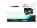
ACS235A
ACS236A
R
G
B
2
1
FIBER KVM
EXTENDER
Power
Remote
Unit
FREE tech support 24 hours a day, 7 days a week: Call 724-746-5500 or fax 724-746-0746.
Mailing address: Black Box Corporation, 1000 Park Dr., Lawrence, PA 15055-1018
World-Wide Web: www.blackbox.com • E-mail: [email protected]
© Copyright 2001. Black Box Corporation. All rights reserved.
Customer Support Information:

1
THE SERVSWITCH™ FAMILY
Welcome to the ServSwitch
TM
Family!
Thank you for purchasing a BLACK BOX
®
ServSwitch
™
Brand KVM-switching
accessory! We appreciate your business, and we think you’ll appreciate the many
ways that your new ServSwitch keyboard/video/mouse switch will save you money,
time, and effort.
That’s because our ServSwitch family is all about breaking away from the
traditional, expensive model of computer management. You know, the one-size-
fits-all-even-if-it-doesn’t model that says, “One computer gets one user station, no
more, no less.” Why not a single user station (monitor, keyboard, and mouse) for
multiple computers—even computers of different platforms? Why not a pair of
user stations, each of which can control multiple computers? Why not multiple
user stations for the same computer?
With our ServSwitch products, there’s no reason why not. We carry a broad line
of robust solutions for all these applications. Do you have just two PCs, and need
an economical alternative to keeping two monitors, keyboards, and mice on your
desk? Or do you need to share dozens of computers, including a mix of IBM
®
PC,
RS/6000
®
, Apple
®
Macintosh
®
, Sun Microsystems
®
, and SGI
®
compatibles among
multiple users with different access levels? Does your switch have to sit solidly on a
worktable and use regular everyday cables? Or does it have to be mounted in an
equipment rack and use convenient many-to-one cables? No matter how large or
small your setup is, no matter how simple or how complex, we’re confident we
have a ServSwitch system that’s just right for you.
The ServSwitch
™
family from Black Box—the one-stop answer for all your KVM-
switching needs!
*
This manual will tell you all about your new ServSwitch™ Brand Fiber KVM
Extender, including how to install, operate, and troubleshoot it. For an
introduction to the Extender, see Chapter 2. The Extender product codes covered
in this manual are:
ACS235A
ACS236A

2
SERVSWITCH™ BRAND FIBER KVM EXTENDERS
DECLARATION OF CONFORMITY
This is to certify that, when installed and used according to the instructions in this
manual together with the specified cables, the ServSwitch™ Brand Fiber KVM
Extender is shielded against the generation of radio interference in accordance
with the application of Council
Directive 89/336/EEC, as well as these standards:
EN 55022: 1989 class B
EN 50082-1: 1993
IEC 801-2: 1991 - 4kV CD/8kV AD
IEC 801-3: 1984 - 3V/m
IEC 801-4: 1988 - 4kV power-supply lines
- 2kV data lines
The Extender was tested in a typical configuration.
TRADEMARKS USED IN THIS MANUAL
BLACK BOX and the logo are registered trademarks, and ServSwitch is a
trademark, of Black Box Corporation.
Apple and Macintosh are registered trademarks of Apple Computer, Inc.
ST is a registered trademark of AT&T
®
.
IBM, PC/AT, and PS/2 are registered trademarks of International Business
Machines Corporation.
Sun and Sun Microsystems are registered trademarks of Sun Microsystems, Inc. in
the United States and other countries.
Any other trademarks mentioned in this manual are acknowledged to be the property of the
trademark owners.

3
FCC/IC STATEMENTS
FEDERAL COMMUNICATIONS COMMISSION AND INDUSTRY CANADA
RADIO-FREQUENCY INTERFERENCE STATEMENTS
This equipment generates, uses, and can radiate radio-frequency energy and if not
installed and used properly, that is, in strict accordance with the manufacturer’s
instructions, may cause interference to radio communication. It has been tested
and found to comply with the limits for a Class A computing device in accordance
with the specifications in Subpart J of Part 15 of FCC rules, which are designed to
provide reasonable protection against such interference when the equipment is
operated in a commercial environment. Operation of this equipment in a
residential area is likely to cause interference, in which case the user at his own
expense will be required to take whatever measures may be necessary to correct the
interference.
Changes or modifications not expressly approved by the party responsible for
compliance could void the user’s authority to operate the equipment.
This digital apparatus does not exceed the Class A limits for radio noise emission from digital
apparatus set out in the Radio Interference Regulation of Industry Canada.
Le présent appareil numérique n’émet pas de bruits radioélectriques dépassant les limites
applicables aux appareils numériques de la classe A prescrites dans le Règlement sur le
brouillage radioélectrique publié par Industrie Canada.

4
SERVSWITCH™ BRAND FIBER KVM EXTENDERS
NORMAS OFICIALES MEXICANAS (NOM)
ELECTRICAL SAFETY STATEMENT
INSTRUCCIONES DE SEGURIDAD
1. Todas las instrucciones de seguridad y operación deberán ser leídas antes de
que el aparato eléctrico sea operado.
2. Las instrucciones de seguridad y operación deberán ser guardadas para
referencia futura.
3. Todas las advertencias en el aparato eléctrico y en sus instrucciones de
operación deben ser respetadas.
4. Todas las instrucciones de operación y uso deben ser seguidas.
5. El aparato eléctrico no deberá ser usado cerca del agua—por ejemplo, cerca
de la tina de baño, lavabo, sótano mojado o cerca de una alberca, etc.
6. El aparato eléctrico debe ser usado únicamente con carritos o pedestales que
sean recomendados por el fabricante.
7. El aparato eléctrico debe ser montado a la pared o al techo sólo como sea
recomendado por el fabricante.
8. Servicio—El usuario no debe intentar dar servicio al equipo eléctrico más allá
a lo descrito en las instrucciones de operación. Todo otro servicio deberá ser
referido a personal de servicio calificado.
9. El aparato eléctrico debe ser situado de tal manera que su posición no
interfiera su uso. La colocación del aparato eléctrico sobre una cama, sofá,
alfombra o superficie similar puede bloquea la ventilación, no se debe colocar
en libreros o gabinetes que impidan el flujo de aire por los orificios de
ventilación.
10. El equipo eléctrico deber ser situado fuera del alcance de fuentes de calor
como radiadores, registros de calor, estufas u otros aparatos (incluyendo
amplificadores) que producen calor.
11. El aparato eléctrico deberá ser connectado a una fuente de poder sólo del
tipo descrito en el instructivo de operación, o como se indique en el aparato.

5
NOM STATEMENT
12. Precaución debe ser tomada de tal manera que la tierra fisica y la polarización
del equipo no sea eliminada.
13. Los cables de la fuente de poder deben ser guiados de tal manera que no
sean pisados ni pellizcados por objetos colocados sobre o contra ellos,
poniendo particular atención a los contactos y receptáculos donde salen del
aparato.
14. El equipo eléctrico debe ser limpiado únicamente de acuerdo a las
recomendaciones del fabricante.
15. En caso de existir, una antena externa deberá ser localizada lejos de las lineas
de energia.
16. El cable de corriente deberá ser desconectado del cuando el equipo no sea
usado por un largo periodo de tiempo.
17. Cuidado debe ser tomado de tal manera que objectos liquidos no sean
derramados sobre la cubierta u orificios de ventilación.
18. Servicio por personal calificado deberá ser provisto cuando:
A: El cable de poder o el contacto ha sido dañado; u
B: Objectos han caído o líquido ha sido derramado dentro del aparato; o
C: El aparato ha sido expuesto a la lluvia; o
D: El aparato parece no operar normalmente o muestra un cambio en su
desempeño; o
E: El aparato ha sido tirado o su cubierta ha sido dañada.

6
SERVSWITCH™ BRAND FIBER KVM EXTENDERS
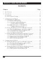
Contents
Chapter Page
1. Specifications ............................................................................................. 8
2. Introduction ............................................................................................. 11
2.1 Overview ............................................................................................ 11
2.2 The Complete Package ..................................................................... 12
3. Configuring the ACS235A ....................................................................... 13
3.1 Configuring for RGB Video ............................................................. 13
3.1.1 VGA vs. RGB Signaling ........................................................... 13
3.1.2 VGA Video Card to RGB Monitor
(VGA to RGB Conversion) ................................................ 13
3.1.3 RGB Video Source to RGB Monitor ...................................... 14
3.1.4 RGB Video Source to VGA Monitor
(RGB to VGA Conversion) ................................................ 14
3.2 Setting the Jumpers in the Local Module (Optional) .................... 16
3.2.1 The VGA/RGB Jumpers (JP6, JP10, and JP11) ..................... 17
3.2.2 VGA-to-RGB Sync-Generation Jumper JP2 ............................ 18
3.2.3 Local Gain-Control Jumper JP3 .............................................. 18
3.2.4 Core-Diameter Jumper JP5 ..................................................... 18
3.3 Setting the Jumpers in the Remote Module (Optional) ................ 19
3.3.1 The Sync-on-Color Jumpers (JP1, JP2, and JP3) ................... 20
3.3.2 Remote Gain-Control Jumper Bank JP8 ................................ 21
3.3.3 VSYNC Enable/Disable Jumper JP9 ...................................... 22
3.3.4 SYNC-Polarity Jumper JP12 .................................................... 22
4. Configuring the ACS236A ....................................................................... 23
4.1 Setting the Jumpers in the Local Module (Optional) .................... 23
4.1.1 The Video-Handling Jumpers JP2 and JP10 .......................... 24
4.1.2 Local Gain-Control Jumper JP3 .............................................. 25
4.1.3 Core-Diameter Jumper JP5 ..................................................... 25
4.3 Setting the Jumpers in the Remote Module (Optional) ................ 26
4.3.1 Remote Gain-Control Jumper Bank JP8 ................................ 27
4.3.2 VSYNC Enable/Disable Jumper JP9 ...................................... 28

7
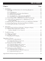
TABLE OF CONTENTS
Chapter Page
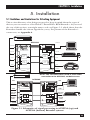
5. Installation ................................................................................................ 29
5.1 Guidelines and Limitations for Attaching Equipment ................... 29
5.1.1 CPU .......................................................................................... 30
5.1.2 VGA Monitor ........................................................................... 30
5.1.3 RGB Monitor or Legacy Sun Monitor ................................... 30
5.1.4 Keyboard and Mouse .............................................................. 31
5.1.5 Parallel Printer (Optional with ACS235A) ............................ 31
5.1.6 Serial Device (Optional with ACS236A) ................................ 31
5.2 Connecting a CPU or KVM Switch to the Local Module ............... 32
5.3 Connecting User Equipment or a KVM Switch to the
Remote Module ........................................................................... 34
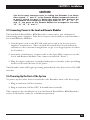
5.4 Running Fiber Cable Between the Local and Remote Modules .... 36
5.5 Connecting Power to the Local and Remote Modules ................... 37
5.6 Powering Up the Rest of the System ................................................ 37
6. Operation ................................................................................................. 38
6.1 Interpreting the Remote Module’s 7-Segment Display .................. 38
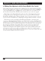
6.2 Making Video Adjustments with the
Remote Module’s User Controls ................................................. 40
7. Troubleshooting ...................................................................................... 41
7.1 Things to Try First ............................................................................. 41
7.2 Calling Black Box .............................................................................. 42
7.3 Shipping and Packaging ................................................................... 42
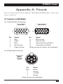
Appendix A: Pinouts ....................................................................................... 43
A.1 Connectors on Both Models ..............................................................43
A.1.1 The VGA Video Connectors ................................................... 43
A.1.2 The Power Connector ............................................................. 43
A.2 Connectors on the ACS235A ............................................................ 44
A.2.1 The PS/2 Keyboard Connector ............................................. 44
A.2.2 The PS/2 Mouse Connector .................................................. 44
A.2.3 The Parallel Printer Connectors ............................................ 45
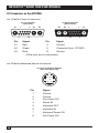
A.3 Connectors on the ACS236A ............................................................ 46
A.3.1 The Sun Video Connectors .................................................... 46
A.3.2 The Sun Keyboard/Mouse Connector .................................. 46
A.3.3 The Serial Connectors ............................................................ 47
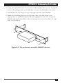
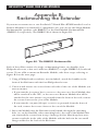
Appendix B: Rackmounting the Extender .................................................... 48

8
SERVSWITCH™ BRAND FIBER KVM EXTENDERS
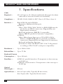
1. Specifications
Cable
Required — 62.5/125-µm or 50/125-µm multimode fiberoptic breakout
cable with at least five strands (not included)
Compliance — CE (EN 55022, 50082-1); FCC Class A, IC Class/classe A
Interfaces — Both ACS235A and ACS236A:
Extension: Multimode fiberoptic;
ACS235A:
Video: VGA, SVGA, XGA, XGA-2, or RGB (RGB must be
patched to an HD15 connector); Plug-and-Play not
supported for monitors;
Keyboard and mouse: IBM PS/2 compatible;
Printer: IBM PC parallel (Centronics compatible);
ACS236A:
Video: Either legacy Sun type or VGA, SVGA, XGA,
XGA-2, or RGB (RGB must be patched to an HD15
connector); Plug-and-Play not supported for monitors;
Keyboard and mouse: Sun type;
Serial device: EIA/TIA RS-232 (ITU V.24/V.28) pinned
according to TIA-574 (PC serial-port compatible)
Resolution — Up to 1280 x 1024
Refresh Rate — Up to 75 Hz
Keyboard Current
Consumption — Up to 100 mA
Data Rate — ACS235A’s parallel interface: Transparent to data rates up
to 20,000 cps;
ACS236A’s serial interface: Transparent to data rates up to
38,400 bps
Optical
Wavelength — 850 nm
Optical Power — Into 62.5-µm cable: Typically 88 microwatts;
Into 50-µm cable: Typically 40 microwatts

9
CHAPTER 1: Specifications
Maximum
Optical Loss — 5 dB
Maximum
Distance — 1000 m (3281 ft.) between Extender’s Local and Remote
Modules
User Controls — Both ACS235A and ACS236A, rear-mounted on the
Remote Module:
(2) Rear-mounted dials for contrast and brightness;
(3) Rear-mounted trimpots for adjusting color-signal
gain;
ACS235A:
(12) Internal jumper sets for configuration options:
(6) inside Local Module, (6) inside Remote Module;
ACS236A:
(7) Internal jumper sets for configuration options:
(4) inside Local Module, (3) inside Remote Module
Indicators — (1) Front-mounted 7-segment LED display;
(2) Rear-mounted LEDs for power
Connectors — Both ACS235A and ACS236A, on both the Local and
Remote Modules:
(5) Rear-mounted ST female for Module-to-Module link;
(1) Front-mounted 6-pin DIN female for power;
ACS235A:
Front-mounted on Local Module:
(2) 6-pin mini-DIN female:
(1) for CPU’s keyboard port,
(1) for CPU’s mouse port;
(1) HD15 male for CPU’s video port;
(1) DB25 male for CPU’s parallel port;
Front-mounted on Remote Module:
(2) 6-pin mini-DIN female:
(1) for keyboard,
(1) for mouse;
(1) HD15 female for monitor;
(1) DB25 female for parallel printer;

10
SERVSWITCH™ BRAND FIBER KVM EXTENDERS
Connectors
(continued) — ACS236A:
Front-mounted on Local Module:
(1) 8-pin mini-DIN female for CPU’s keyboard and
mouse ports;
(1) HD15 male for CPU’s video port (if it’s VGA type);
(1) 13W3 male for CPU’s video port (if it’s legacy Sun
type);
(1) DB9 female for CPU’s serial port;
Front-mounted on Remote Module:
(1) 8-pin mini-DIN female for keyboard and mouse;
(1) 13W3 female for monitor (if it’s legacy Sun type);
(1) HD15 female for monitor (if it’s VGA or multisync
type);
(1) DB9 male for serial device
Temperature
Tolerance — Operating: 50 to 113˚F (10 to 45˚C);
Storage: 23 to 131˚F (–5 to +55˚C)
Humidity
Tolerance — Up to 80% noncondensing
Power — From utility-power (mains) outlet, through external
transformer:
Input: 100 to 240 VAC, 47 to 63 Hz, autosensing, at up to
0.7 amps;
Output: +12 VDC at 2.1 amps;
Consumption:
Local Module: Approx. 8 watts;
Remote Module without keyboard: Approx. 8 watts;
Remote Module with keyboard: Approx. 9 watts
Size — Each Module: 2.2"H x 6.3"W x 7.5"D (5.6 x 16 x 19.1 cm)
Weight — Net for each Module: 2 lb. (0.9 kg);
Shipping (both Modules plus accessories): At least 7.7 lb.
(3.5 kg)

11
CHAPTER 2: Introduction
2. Introduction
2.1 Overview
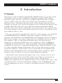
The purpose of the ServSwitch™ Brand Fiber KVM Extender is to greatly extend
the distance between a Sun
®
or IBM
®
PC compatible computer CPU and the
keyboard, mouse, monitor, and serial or parallel peripheral that the computer
operator will be using, especially in electrically noisy environments. Normal
keyboard-, video-, and mouse-extension cables (and extenders that use normal
cabling) can only go so far, and electromagnetic noise can limit their distance and
reliability. But with a fiberoptic system like the ServSwitch Brand Fiber KVM
Extender, these concerns are a thing of the past. You can leave the computer CPU
in a secured cabinet or data center while you operate it from a convenient location
up to 1000 m (3281 ft.) away.
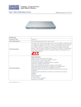
There are two models of the Extender. The PC version (product code ACS235A)
extends KVM distance for IBM PC compatible computers. The Sun version
(product code ACS236A) extends KVM distance for Sun Microsystems
®
computers.
Each model consists of two main components: a Local Module that you’ll attach
the computer’s CPU to, and a Remote Module that you’ll attach the user
equipment to. (With the ACS235A, the “user equipment” will be an IBM PS/2
®
compatible keyboard and mouse, VGA type monitor, and an optional IBM PC
compatible or Centronics
®
compatible parallel printer. With the ACS236A, it will
be a Sun compatible keyboard and mouse, VGA or legacy Sun monitor, and an
optional serial device.) You’ll connect the two units with a five-strand fiberoptic
breakout cable. With this Extender, you’ll get high monitor resolution, optical
isolation, and color fidelity, even in electrically rough surroundings.
The Extender units automatically adapt to the correct transfer rates for all of
your data; you won’t need to manually set these rates. There is one setting you
might need to make after you start operating the units: The Extenders’
amplification might need to be adjusted if you use very long fiberoptic cables. (The
controls for this are located on the Remote Module—refer to Section 6.2.) And
even this adjustment is easy to “eyeball” by watching the picture on the monitor
screen.

12
SERVSWITCH™ BRAND FIBER KVM EXTENDERS
2.2 The Complete Package
Before you do anything else with it, verify that you received everything you should
have with your ServSwitch Brand Fiber KVM Extender. These components come
with both models of the Extender:
• The Extender’s Local Module.
• The Extender’s Remote Module.
• (2) power supplies, one for each Module.
• (2) power cords, one for each power supply (equivalent to our product code
EPWR08).
• (1) set of eight adhesive feet.
• This manual.
The ACS235A also comes with these components:
• (1) 10-ft. (3-m) keyboard/video/mouse CPU-extension cable with an HD15
female video connector and 6-pin mini-DIN keyboard and mouse connectors
(equivalent to our product code EHN235-0010).
• (1) 10-ft. (3-m) DB25 male to DB25 female IBM PC parallel (Centronics
compatible) extension cable (equivalent to our product code BC00705).
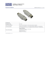
• (1) 6-in. (15.2-cm) PC/AT
®
keyboard-port adapter (6-pin mini-DIN female to
5-pin DIN male, equivalent to our product code FA222).
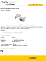
• (1) RS-232 serial mouse-port adapter (6-pin mini-DIN female to DB9 female,
equivalent to our product code AC244A).
The ACS236A also comes with this cable:
• (1) 10-ft. (3-m) keyboard/video/mouse CPU-extension cable with an HD15
female video connector and an 8-pin mini-DIN keyboard/mouse connector
(equivalent to our product code EHN236-0010).
If anything is missing, contact Black Box right away. If the package has been
damaged, contact both Black Box and the shipping carrier.

13
CHAPTER 3: Configuring the ACS235A
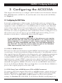
3. Configuring the ACS235A
This chapter describes how to configure the PC model of the ServSwitch™ Brand
Fiber KVM Extender (ACS235A). If your Extender is the Sun model (ACS236A),
see Chapter 4.
3.1 Configuring for RGB Video
In normal configuration at delivery time, the Extender units are configured to
carry video from a VGA source to a VGA monitor. But if you’d like to attach RGB
equipment (either an RGB source or an RGB monitor or both) to your Extender
system, this section discusses how you might need to set the units’ configuration
jumpers. (See Table 3-1 on page 15 for a full layout of this.) Of course, RGB video
can come in a variety of signal forms and combinations. If after reading the rest of
this section you’re not sure how to get your RGB application working (or even
whether it can be done), call Black Box for technical support.
NOTE
In any application involving RGB video, if the picture on your monitor
looks OK with AGC ON, leave the Local Module’s JP3 jumper and the
Remote Module’s JP8 jumpers in their factory settings. Otherwise,
remove JP3 at the Local Module and move JP8 at the Remote Module to
turn AGC OFF. You will then have to adjust the gain of the Extenders’
video signal manually. See Sections 3.2.3 and 3.3.2.
3.1.1 VGA
VS
. RGB S
IGNALING
VGA uses two video-synchronization signals, HSYNC (horizontal sync) and VSYNC
(vertical sync). In its factory-default settings, the Extender’s Local Module receives
these signals from the CPU and overlays them on the color signals for transmission
to the Remote Module: HSYNC on green, VSYNC on blue, and SYNCPOL (the
combined HSYNC and VSYNC polarity information) on red. But most RGB
applications use a single CSYNC (composite sync) signal overlaid on the green
color signal instead, so for such applications you’ll need to have the Local Module
substitute this signal for HSYNC, as well as create its own SYNCPOL information
for use by the Remote Module. Then you might have to set the Remote Module to
process these signals properly at the other end.
3.1.2 VGA V
IDEO
C
ARD TO
RGB M
ONITOR
(VGA
TO
RGB C
ONVERSION
)
To connect a CPU that outputs VGA video to an RGB monitor, remove the Local
Module’s JP2 jumper (so that it generates the CSYNC signal needed by the RGB
monitor), but leave the JP6, JP10, and JP11 jumpers in their factory-default
settings (see Sections 3.2.1 and 3.2.2). At the Remote Module, install jumpers at

14
SERVSWITCH™ BRAND FIBER KVM EXTENDERS
the JP1, JP2, and JP3 locations to deactivate the decoupling diodes (so that the
Remote Module leaves the sync signals on the color signals), and remove the
jumpers at JP9 and JP12 to disable VSYNC and force the sync polarity signals
negative (see Sections 3.3.1, 3.3.3, and 3.3.4).
CAUTION!
You can only connect an RGB monitor to a VGA source if the monitor is
able to process the source’s synchronization frequency; for example,
the monitor of a graphic workstation with horizontal bandwidth of 40 to
90 kHz probably won’t work with a VGA graphics adapter that has a
resolution of 640 x 480 = 31.5 kHz.
3.1.3 RGB V
IDEO
S
OURCE TO
RGB M
ONITOR
To connect an RGB video source to an RGB monitor, set the Local Module’s JP6,
JP10, and JP11 jumpers all to the “RGB settings” (the ones opposite the factory
defaults; see Section 3.2.1). At the Remote Module, install jumpers at the JP1, JP2,
and JP3 locations to deactivate the decoupling diodes (so that the Remote Module
leaves the sync signals on the color signals; see Section 3.3.1).
3.1.4 RGB V
IDEO
S
OURCE TO
VGA M
ONITOR
(RGB
TO
VGA C
ONVERSION
)
To connect an RGB video source to a VGA monitor, set the Local Module’s JP6,
JP10, and JP11 jumpers all to the “RGB settings” (the ones opposite the factory
defaults), but leave jumper JP2 in its factory setting so that HSYNC, not CSYNC, is
transmitted on the HSYNC lead. Remove the Remote Module’s JP12 jumper in
order to force polarity negative. See Sections 3.2.1 and 3.3.4. In this application,
the Remote Module also functions as a sync stripper: It strips the sync signals from
the color signals, separates them, and presents them as normal TTL signals to the
VGA monitor.
IMPORTANT NOTES
You can only connect a VGA monitor to an RGB video source if the
monitor is able to process the source’s synchronization frequency; for
example, a multisync monitor with horizontal bandwidth of 30 to 90 kHz
probably won’t work with a WF470 graphics adapter that uses a
frequency of 15.625 kHz.
The Extender can not generate the special VGA-standard phase
relation required by some types of dual-scan monitors (LCD panels, etc.).
Be aware that, because of the way some RGB cards output sync
signals, it is possible that, despite how the jumpers are set in your Local
Module, your monitor will still receive CSYNC on its HSYNC lead as well
as VSYNC on its VSYNC lead. Some VGA monitors have no problem
with this, but others will suffer from distorted displays. If your monitor is
affected by this distortion, you can suppress the VSYNC signal by
removing the Remote Module’s JP9 jumper; the monitor should work
fine using CSYNC only. See Section 3.3.3.
Siemens
®
users: The Extender can process CP581 signals, but this
requires special cabling. Call Black Box for technical support.

15
CHAPTER 3: Configuring the ACS235A
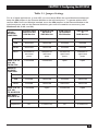
Table 3-1. Jumper Settings
For all of these applications, to use AGC you must leave JP3 in the Local Module installed and
keep the JP8 jumpers in the Remote Module on the left-hand posts. To operate without AGC,
remove JP3 in the Local Module installed, move the JP8 jumpers in the Remote Module to the
right-hand posts, and use the Remote Module’s gain-control screwdials as necessary (see
Sections 3.2.3, 3.3.2, and 5.2).
LOCAL
Standard VGA Standard VGA RGB Source RGB Source
MODULE
Source to Std. Source to to Standard to
JUMPERS:
VGA Monitor RGB Monitor VGA Monitor RGB Monitor
JP2 Installed Removed Installed Installed
JP6 Removed Removed Installed Installed
JP10 Removed Removed Installed Installed
JP11 Installed on Installed on Installed on Installed on
left-hand left-hand right-hand right-hand
posts posts posts posts
PINS 13 & 14 Connected Connected Open Open
(HS, VS)
FROM CPU
REMOTE-
MODULE
JUMPERS:
JP1, 2, 3 Removed Installed Removed Installed
JP9 Installed Removed Installed Removed
JP12 Installed Removed Removed Removed
PINS 13 & 14 Connected Open Connected Open
(HS, VS)
TO MONITOR
USE RM’S
CONTROLS?
Contrast If necessary If necessary If necessary If necessary
Brightness No If necessary No If necessary

16
SERVSWITCH™ BRAND FIBER KVM EXTENDERS
3.2 Setting the Jumpers in the Local Module (Optional)
There are six user-settable jumpers inside the Local Module of the ServSwitch
Brand Fiber KVM Extender. They control these options:
• Whether the Local Module transmits VGA (default) or RGB video signals to
the Remote Module, and if RGB, which signals and how (jumpers JP6, JP10,
and JP11).
• Whether the Local Module transmits HSYNC (default) or CSYNC to the
Remote Module (jumper JP2).
• Whether the Local Module uses automatic (default) or manual gain control
(jumper JP3).
• Whether the Local Module expects to transmit into 62.5/125-µm (default) or
50/125-µm fiber (jumper JP5).
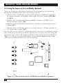
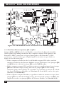
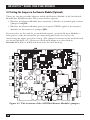
If you need to set the unit for a non-default option, open the Local Module—being
sure to take all reasonable precautions against static electricity—by unscrewing the
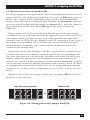
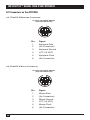
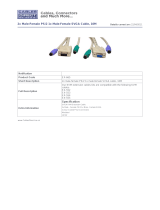
upper part of its casing. (The jumper locations on the motherboard are shown in
Figure 3-1.) Then set your desired jumpers as described in Sections 3.2.1, 3.2.2,
3.2.3, and/or 3.2.4, and then close the unit back up.
Figure 3-1. The locations of the ACS235A Local Module’s jumpers.
A
A
JP11
JP6
JP10
JP5
JP4
JP3
JP2

17
CHAPTER 3: Configuring the ACS235A
3.2.1 T
HE
VGA/RGB J
UMPERS
(JP6, JP10,
AND
JP11)
If you’ll be using a VGA monitor in your Extender system, leave these jumpers set
as they are (in their factory-default positions). But if you need to use an RGB
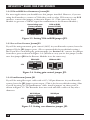
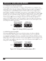
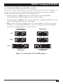
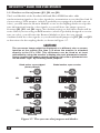
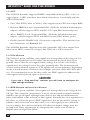
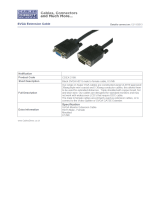
monitor instead, take these steps (refer to Figure 3-2):
• Install a jumper on JP6 if you want the Extender to add the HSYNC
(horizontal sync) polarity signal to the red color signal.
• Install a jumper on JP10 if you want the Extender to add the VSYNC (vertical
sync) polarity signal to the red color signal.
• JP11 is the main VGA vs. RGB control. To select RGB on the local side (if your
computer is transmitting RGB video), move the jumper from the left-hand
posts to the right-hand posts, as shown below.
Figure 3-2. Setting the VGA/RGB jumpers.
Installed
Removed
Removed
Installed
Jumper on right-
hand posts
Jumper on left-
hand posts
JP6
JP10
JP11
VGA Signals
(Factory Defaults)
RGB Signals

18
SERVSWITCH™ BRAND FIBER KVM EXTENDERS
3.2.2 VGA-
TO
-RGB S
YNC
-G
ENERATION
J
UMPER
JP2
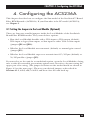
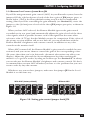
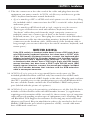
For most applications you should leave this jumper installed. However, if you are
using the Extender to connect a VGA video card or other VGA source to an RGB
monitor, remove this jumper as shown in Figure 3-3. (This causes the Local
Module to generate a CSYNC signal for transmission to the Remote Module.)
Figure 3-3. Setting VGA-to-RGB jumper JP2.
3.2.3 L
OCAL
G
AIN
-C
ONTROL
J
UMPER
JP3
If you’ll be using automatic gain control (AGC) in your Extender system, leave the
jumper ON the JP3 jumper posts. (We recommend this factory-default setting.)
But if you’ll be controlling the gain manually (see Section 5.2), remove the jumper
from these posts as shown in Figure 3-4. (Whichever way you set this jumper, make
sure that jumper JP8 in the Remote Module is set the same way.)
Figure 3-4. Setting gain-control jumper JP3.
3.2.4 C
ORE
-D
IAMETER
J
UMPER
JP5
If you’ll be using fiberoptic cable with a 62.5/125-µm diameter in your Extender
system, leave the JP5 jumper posts empty. (This is the factory-default setting.) But
if you’ll be using 50/125-µm-diameter cable, install a jumper on these posts as
shown in Figure 3-5. The Extender does not work with fiber cables of any other
diameter.
Figure 3-5. Setting core-diameter jumper JP5.
JP2
Removed
Installed
Use existing sync
(factory default)
VGA to RGB
(create CSYNC)
JP3
Removed
Installed
With AGC
(factory default)
Without AGC
JP5
Installed
Removed
62.5/125-µm
(factory default)
50/125-µm

19
CHAPTER 3: Configuring the ACS235A
3.3 Setting the Jumpers in the Remote Module (Optional)
There are six user-settable jumpers inside the Remote Module of the ServSwitch
Brand Fiber KVM Extender. They control these options:
• Whether the Remote Module strips the sync signals from the color signals
(default) or leaves them in (jumpers JP1, JP2, and JP3).
• Whether the Remote Module uses automatic (default) or manual gain control
(jumper bank JP8).
• Whether the Remote Module passes a separate VSYNC signal to the monitor
(default) or disconnects it (jumper JP9).
• Whether the Remote Module uses the SYNC polarities transmitted from the
local side (default) or forces both HSYNC and VSYNC to negative polarity
(jumper JP12).
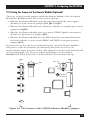
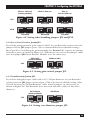
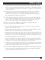
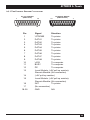
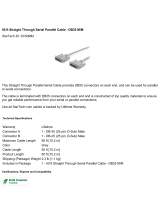
If you need to set the unit for a non-default option, open the Remote Module—
being sure to take all reasonable precautions against static electricity—by
unscrewing the upper part of its casing. (The jumper locations on the motherboard
are shown in Figure 3-6.) Then set your desired jumpers as described in
Sections 3.3.1, 3.3.2, 3.3.3, and/or 3.3.4, and then close the unit back up.
Figure 3-6. The locations of the ACS235A Remote Module’s jumpers.
K
A
JP1, 2, 3
JP9
JP11
JP12
JP8
Page is loading ...
Page is loading ...
Page is loading ...
Page is loading ...
Page is loading ...
Page is loading ...
Page is loading ...
Page is loading ...
Page is loading ...
Page is loading ...
Page is loading ...
Page is loading ...
Page is loading ...
Page is loading ...
Page is loading ...
Page is loading ...
Page is loading ...
Page is loading ...
Page is loading ...
Page is loading ...
Page is loading ...
Page is loading ...
Page is loading ...
Page is loading ...
Page is loading ...
Page is loading ...
Page is loading ...
Page is loading ...
Page is loading ...
Page is loading ...
Page is loading ...
Page is loading ...
Page is loading ...
Page is loading ...
Page is loading ...
Page is loading ...
Page is loading ...
Page is loading ...
Page is loading ...
Page is loading ...
Page is loading ...
Page is loading ...
Page is loading ...
Page is loading ...
Page is loading ...
Page is loading ...
Page is loading ...
Page is loading ...
Page is loading ...
Page is loading ...
Page is loading ...
Page is loading ...
Page is loading ...
Page is loading ...
Page is loading ...
Page is loading ...
Page is loading ...
Page is loading ...
Page is loading ...
Page is loading ...
Page is loading ...
Page is loading ...
Page is loading ...
Page is loading ...
Page is loading ...
Page is loading ...
Page is loading ...
Page is loading ...
Page is loading ...
Page is loading ...
Page is loading ...
Page is loading ...
Page is loading ...
Page is loading ...
Page is loading ...
Page is loading ...
Page is loading ...
Page is loading ...
Page is loading ...
Page is loading ...
Page is loading ...
Page is loading ...
Page is loading ...
-
 1
1
-
 2
2
-
 3
3
-
 4
4
-
 5
5
-
 6
6
-
 7
7
-
 8
8
-
 9
9
-
 10
10
-
 11
11
-
 12
12
-
 13
13
-
 14
14
-
 15
15
-
 16
16
-
 17
17
-
 18
18
-
 19
19
-
 20
20
-
 21
21
-
 22
22
-
 23
23
-
 24
24
-
 25
25
-
 26
26
-
 27
27
-
 28
28
-
 29
29
-
 30
30
-
 31
31
-
 32
32
-
 33
33
-
 34
34
-
 35
35
-
 36
36
-
 37
37
-
 38
38
-
 39
39
-
 40
40
-
 41
41
-
 42
42
-
 43
43
-
 44
44
-
 45
45
-
 46
46
-
 47
47
-
 48
48
-
 49
49
-
 50
50
-
 51
51
-
 52
52
-
 53
53
-
 54
54
-
 55
55
-
 56
56
-
 57
57
-
 58
58
-
 59
59
-
 60
60
-
 61
61
-
 62
62
-
 63
63
-
 64
64
-
 65
65
-
 66
66
-
 67
67
-
 68
68
-
 69
69
-
 70
70
-
 71
71
-
 72
72
-
 73
73
-
 74
74
-
 75
75
-
 76
76
-
 77
77
-
 78
78
-
 79
79
-
 80
80
-
 81
81
-
 82
82
-
 83
83
-
 84
84
-
 85
85
-
 86
86
-
 87
87
-
 88
88
-
 89
89
-
 90
90
-
 91
91
-
 92
92
-
 93
93
-
 94
94
-
 95
95
-
 96
96
-
 97
97
-
 98
98
-
 99
99
-
 100
100
-
 101
101
-
 102
102
-
 103
103


Black Box ACS235A User manual
- Category
- Console extenders
- Type
- User manual
- This manual is also suitable for
Ask a question and I''ll find the answer in the document
Finding information in a document is now easier with AI
Related papers
-
Black Box TS000A Datasheet
-
Black Box ServSwitch II-SM ACS251A User manual
-
-
-
-
-
-
-
-
Other documents
-
 Cables Direct KVM-512 Datasheet
-
 StarTech.com GC96MM Datasheet
-
 Cables Direct AD-302 Datasheet
-
 Cables Direct AD-310 Datasheet
-
 Cables Direct EX-665 Datasheet
-
 Cables Direct CDEX-216K Datasheet
-
 StarTech.com SC50MM Datasheet
-
 Cables Direct EX-024 Datasheet
-
 Cables Direct EX-022 Datasheet
-
 Cables Direct EX-023 Datasheet


