Page is loading ...

Rugby 55
User Manual
Version 1.0
English

IIRugby 55
Introduction
Congratulations on the purchase of a new Rotating Laser product.
Product The Rugby 55 is a laser tool for interior, general construction and other leveling
applications. It is engineered and built with the latest innovations in the laser
tool industry. It is designed to be easy to set up, simple to operate and highly
dependable.
This manual contains important safety directions as well as instructions for
setting up the product and operating it. Refer to "9 Safety Directions" for
further information.
Read carefully through the User Manual before you switch on the product.
Product Identifica-
tion
The model and the serial number of your product are indicated on the type
plate.
Enter the model and serial number in your manual and always refer to this
information when you need to contact your agency or Leica Geosystems
authorized service workshop.
Type: _______________
Serial No.: _______________

IIIRugby 55
Symbols The symbols used in this manual have the following meanings:
Trademarks All trademarks are the property of their respective owners.
Type Description
Danger Indicates an imminently hazardous situation which, if not
avoided, will result in death or serious injury.
Warning Indicates a potentially hazardous situation or an unin-
tended use which, if not avoided, could result in death or
serious injury.
Caution Indicates a potentially hazardous situation or an unin-
tended use which, if not avoided, may result in minor or
moderate injury and/or appreciable material, financial and
environmental damage.
)Important paragraphs which must be adhered to in prac-
tice as they enable the product to be used in a technically
correct and efficient manner.

IVRugby 55
Table of Contents
In this manual Chapter Page
1Description of the System .......................................................1-1
2Basic Operation .......................................................................2-1
3Accessories ..............................................................................3-1
4Applications .............................................................................4-1
5Batteries ..................................................................................5-1
6Accuracy Adjustment ...............................................................6-1
7Troubleshooting.......................................................................7-1
8Care and Transport ..................................................................8-1
9Safety Directions .....................................................................9-1
10 Technical Data .......................................................................10-1
Index .................................................................................................i-1

1-1Rugby 55Description of the System
1Description of the System
1.1 Features
Precision Designed to maintain its accuracy on the toughest of jobs, the Rugby 55
projects a rotating beam usable up to 150 meters (500 feet) with a receiver.
Simplicity The Rugby 55 is designed to be versatile, easy to operate and having features
that serve both the interior and general construction contractor well. A bright,
visible beam, variable head speed, scanning motion, horizontal and vertical
self-leveling, split beam and great battery life, combine to provide consistent
value for the professional contractor.
Ruggedness Engineered for construction environment, the Rugby 55 will provide reliable
performance day after day.

1-2Rugby 55Description of the System
1.2 Rugby Components
a) Window assembly and rotating head
b) Membrane switch panel
c) Battery door and locking knob
d) Charge port with LED (rechargeable models)
e) Carrying handle (on back)
f) 5/8”-11 mounting holes (on back and bottom)
g) Positioning guides
a
b
c
d
e
f
g

1-3Rugby 55Description of the System
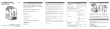
1.3 Rugby 55 Membrane Switch Panel
a) Low Battery LED
b) Left / Right Positioning Buttons
c) Scanning Button
d) Head Speed Button (rps)
e) X/Y Axis Level Indication LED’s
f) Power Button
g) CW / CCW Arrow Buttons
a
b
c
d
e
f
g

1-4Rugby 55Description of the System
1.4 Case Component Locator, Interior Case
a) Wall mount bracket
b) Spare battery holder
c) Alkaline batteries
d) Remote control
e) Ceiling grid targets
f) User manual
g) Receiver
h) Rugby 55
i) Accessories compartment
a
b
c
d
e
f
g
h
i

1-5Rugby 55Description of the System
1.5 Case Component Locator, Standard Case
a) User manual
b) Accessories and second receiver
c) Spare batteries, D-cells
d) Spare battery pack, NiMH
e) Receiver
f) Rugby
a
b
c
d
e
f

2-1Rugby 55Basic Operation
2Basic Operation
In this chapter
Topic Page
2.1 Introduction ........................................................................2-2
2.2 The LED Indicators ..............................................................2-3
2.3 The Switch Buttons .............................................................2-4
2.4 Special Features..................................................................2-6
2.5 Manual Mode with cross axis self-leveling..........................2-9
2.6 The Elevation Alert (H.I.) Function ....................................2-12

2-2Rugby 55Basic Operation
2.1 Introduction
The Rugby 55 is easy to understand and simple to use. The descriptions of the
LED’s and Switch Buttons that follow will explain their basic functions.
The Rugby 55 is designed to serve you in a variety of applications. Developed
specifically for the interior contractor. the Rugby 55 can also be used together
with a laser receiver for many outdoor, general construction applications.
This manual contains operating and set-up procedures for common applica-
tions. Its purpose is to describe the features of the Rugby 55 and how it oper-
ates. This manual is not intended to describe specific applications. Contact
Leica Geosystems or your distributor for information specific to your jobsite
requirements.

2-3Rugby 55Basic Operation
2.2 The LED Indicators
The LED Indicators have three main functions
• To indicate the level status of the axes.
• To indicate the battery status.
• To indicate an H.I. Alert condition.
Additional functions will be described for specific conditions later in this
manual.
(a) X and Y Indicators (a) - Indicate the level status.
• Green - Indicates the axis is level.
• Green Flashing - Indicates the axis is leveling.
• Red - Indicates the axis is in Manual mode.
• Both Flashing Red - Indicates an H.I. Alert condition (if H.I. is enabled).
(b) Low Battery Indicator (b)
When the LED is off, the battery is still good. When it is flashing slowly the
battery is getting low. When the LED begins to flash rapidly it is time to change
the batteries.
H.I.
Y
X

2-4Rugby 55Basic Operation
2.3 The Switch Buttons
Off / On Power Button
• Press to turn the Rugby On and Off
Head Speed Button
• Press to change the speed of the head rotation - 0 • 2 • 5 • 10 rps
Scan Mode Button
• Press to change the width of the scanning beam - 10° • 45° • 90° • 180°
Automatic / Manual Mode Button
• Press to change the Y-axis to manual mode • with X-axis self-leveling
• Press again to change the X-axis to manual mode • with Y-axis self-leveling
• Press again to change both axes to manual mode • with no self-leveling
• Press again to change back to full automatic mode.
Note the changes in the LED indicators in these manual modes. The red LED
indicates that the axis is in manual mode.

2-5Rugby 55Basic Operation
Clockwise and Counter-Clockwise Buttons (CW & CCW)
• Press to rotate the stationary and scanning beam in a CW or CCW motion
Manual Mode, Slope and Layout Buttons
• Press to tilt the axis that is set to manual mode
• In the laydown position, press to align the rotating and 90° split beam

2-6Rugby 55Basic Operation
2.4 Special Features
Beam Down
• Press the Head Speed Button to stop the rotating head (zero rps). The
position of the beam will automatically move to the “downward” position
to allow the user to align the Rugby over a reference point on the floor.
Changing to 0-rps, positions the beam in the plumb down position.

2-7Rugby 55Basic Operation
Scan-90 and Scan-Memory
• Press and hold either the CW or CCW button, then press the
Scan or Head Speed Button to quickly move the scanning or
stationary beam at 90° intervals. In scan mode, the scan
width will automatically change to the smallest scan width
when this function is activated.
• For layout work, use the Beam Down feature (a) to position
the beam over a reference point. Then, use the Scan-90
feature (b) to quickly move the small scan to a position to the
left or right of the laser.
• For ceiling applications and marking elevations, the Scan-90
feature can quickly bring the scanning beam to you.
• Scan Memory means that you can switch to rotational or
stationary mode and the scan will return to the previous posi-
tion wheh scanning motion is again chosen.
+
+
a
b

2-8Rugby 55Basic Operation
Sleep Mode
• Press both the Up and Down buttons simultaneously on the Remote to put
the Rugby 55 into Sleep Mode.
• During Sleep Mode all functions are disabled.
• The Low battery indicator will flash once every ten seconds to indicate that
the unit is in sleep mode.
• The Rugby will sleep for up to two hours, then will shut off automatically
and must be turned on again at the laser.
• When in Sleep Mode, pressing any key will wake the unit and normal oper-
ation will resume.
+

2-9Rugby 55Basic Operation
2.5 Manual Mode with cross axis self-leveling
The Rugby is designed to always start up in automatic mode *
*) It may be desirable to save a manual setup. The automatic mode on start
up can be disabled using a special procedure found in the Troubleshooting
section.
Press the Auto/Manual Button once to change the Y-axis to manual
mode
• The Y-axis will not self-level and slope can be entered in this axis using the
arrow buttons on the Rugby or the remote control.
• The X-axis will continue to self-level.
• The Y-axis LED will be red.
• The X-axis LED will blink green until level.
H.I.
Y
X
When the Y-axis is in manual mode, the Y-axis can be sloped
as illustrated here.
The X and Y axes are marked on the top of the Rugby.

2-10Rugby 55Basic Operation
Press the Auto/Manual Button again to change the X-axis to manual
mode
• The X-axis will not self-level and slope can be entered in this axis using the
arrow buttons on the Rugby or the remote control.
• The X-axis LED will be red
• The Y-axis will continue to self-level
• The Y-axis LED will blink green until level.
When the X-axis is in manual mode, the X-axis can be sloped
as illustrated here.
The X and Y axes are marked on the top of the Rugby.
H.I.
Y
X

2-11Rugby 55Basic Operation
Press the Auto/Manual Button again to change to full manual mode
• Both the X-axis and Y-axis will not self-level and slope can be entered in
either or both axes using the arrow buttons on the Rugby (Y-axis) or the
remote control (either axis).
• The X-axis LED will be red.
• The Y-axis LED will be red.
H.I.
Y
X
When both the X and Y axes are in manual mode, both axes
can be sloped as illustrated here.
The X and Y axes are marked on the top of the Rugby.
/