Page is loading ...

BEOLINK
Master Control Link Handbook

MASTER CONTROL LINK
PREFACE
This handbook deals with Bang & Olufsen’s BeoLink System and AV
system, paying special attention to the installation requirements applying
to them. Consequently, this handbook is especially addressed to dealers
and installers.
Any product, for example a stereo system, a PC, a natural gas system, etc.,
that has to be incorporated into a network needs to have certain
requirements satisfied by the surroundings in connection with its
installation. These requirements must ensure the optimal operation of the
system after installation.
The same applies to Bang & Olufsen’s BeoLink System and AV system.
Although the requirements are not many, it is essential that they be
known since compliance with the basic requirements often determines
whether or not the system is able to operate once the installation has
been completed.
This handbook gives a brief and precise introduction to the basic rules for
the MCL product programme until 1994. The rules must be observed in
connection with the installation of a BeoLink System and/or an AV system.
The handbook has been designed partially as a reference book but the
entire handbook should be read in order to obtain the total overview.
Only then will it serve its purpose as a reference book.

MASTER CONTROL LINK
CONTENTS
READING INSTRUCTIONS
How should I read the handbook?
GENERAL DESCRIPTION OF BEOLINK SYSTEM AND AV SYSTEM
What is a BeoLink System/AV system, and what can they do for me?
TECHNICAL DESCRIPTION
Description of various cables which are typically used in AV &
BeoLink Systems
PRODUCT DESCRIPTION
Description of X-tra kit and IWS 2000
SETUPS
Description of recommended Master Control Link System/AV system
setups, special setups and option programming
SETUPS WITH LIGHT CONTROL
Description of how Light Control can be included in the recommended
setups
DIMENSIONING OF BEOLINK SYSTEM/AV SYSTEM
Description of how many X-tra kits and how much cable may be used
INSTALLATION TYPES
Description of various installation types
INSTALLATION TIPS
Practical advice for use in connection with installation
TROUBLE SHOOTING GUIDE
What could be wrong when the system will not operate
GLOSSARY
Description of specific words and abbreviations
ACCESSORIES LIST
1
2
3
6
14
24
25
27
29
32
35
37

MASTER CONTROL LINK
READING INSTRUCTIONS
The hardware (plugs, cables, X-tra kits, etc.) used for connecting Bang &
Olufsen’s products into a system is always the same, no matter if it is a
Beocenter 9500 and an MX 6000 that have to be connected or if it is a
Beomaster 7000 and an MX 6000, for example.
The handbook employs various symbols to illustrate audio products, video
products and speakers. Unless otherwise stated in the text, these symbols
merely have to be understood as covering one of these product areas and
not as the specific product which the illustration may depict.
Since the handbook is focusing particularly on the basic rules in
connection with the installation of the systems, variables which are
specific to particular products have been omitted to the greatest possible
extent. This means that the handbook will always be relevant in
connection with installation of Master Control Link Systems and AV
systems; both with regard to products launched prior to the publication
of the handbook and products that will be launched later.
Because the basic rules applying to the AV and Master Control Link
Systems will always be the same.
If information specific to a particular product is required, please see Bang
& Olufsen’s Product Configuration Guide.
1

MASTER CONTROL LINK
What is an AV system?
GENERAL DESCRIPTION
2
When a Bang & Olufsen audio system and video system are interconnected,
they make up an AV system.
An AV system offers a number of possibilities which are not accessible if
the products are placed as independent products. For example, in an AV
system the sound can be moved from the TV to the audio system
speakers; a function that proves its excellence when the sound and the
picture have to merge into a higher synthesis. The sound from the audio
system can similarly be moved to the TV speakers. This function comes in
handy if you wish to record sound from the audio system on the video
tape recorder, for example.
The interconnection of the audio and video systems is furthermore a
condition for distributing and operating video sources (satellite, TV and
video tape recorder) to and from other rooms in the house.
What is a BeoLink System?
BeoLink System is a common denominator for those elements which
enable the distribution of sound and picture to different rooms in the
house.
In other words, the BeoLink System enables operation and enjoyment of a
centrally placed audio/video system from different rooms in the house.
Some of the basic elements included therein are:
The obligatory 7-conductor Master Control Link cable (MCL cable), X-tra
kit, relay boxes, MCL 2 AV panel and IWS 2000.
So, with a centrally placed audio system and a BeoLink System it is
possible to listen to and operate e.g. a radio, CD player, tape recorder,
etc. from other rooms.
If the centrally placed audio system is connected with a video system,
thereby forming an AV system, a host of new possibilities are made
available. This further allows the distribution of video sources to other
rooms. In addition to listening to and operating the audio system from
different rooms, it is also possible to watch, listen to and operate the
video system from other rooms.
For example, you can listen to the TV news through the speakers in the
kitchen; or you can watch and operate satellite TV and the video tape
recorder via the TV in the bedroom. Encoded TV and satellite programmes
can also be watched in the link room, provided that a decoder is
connected in the main room. Another possibility is to listen to the radio
via the TV in the bedroom, for example.

MASTER CONTROL LINK
TECHNICAL DESCRIPTION
The following section contains a brief description of the cabling typically
used in connection with an AV and Master Control Link System installation.
Pictures (satellite, video tape recorder and ordinary TV broadcasts) are
distributed through a 75 ohm coaxial cable.
All plugs and sockets are illustrated from the solder side.
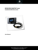
➀Datalink cable
➁Master Control Link cable
MCL cable between audio system and
7-pin terminal strip:
green = signal, right channel
brown= ground, right channel
pink = DC supply
yellow= signal, left channel
grey = ground, left channel
white = Datalink
shield = data shield
3
7-pin DIN cable for connection of
audio and video systems:
pin 1 = yellow = output, left channel
pin 2 = shield = signal ground
pin 3 = blue = input, left channel
pin 4 = red = output, right channel
pin 5 = green = input, right channel
pin 6 = black = data ground
pin 7 = white = Datalink

MASTER CONTROL LINK
4
➁Master Control Link cable
MCL cable between audio system and
8-pin wall socket:
pin 1 = yellow = signal, left channel
pin 2 = pink = DC supply
pin 3 = grey = ground, left channel
pin 4 = green = signal, right channel
pin 5 = brown = ground, right channel
pin 6 = white = Datalink
pin 7 = shield = data shield
➂Power Link cable
➂Thin Power Link cable
pin 2 = shield = ground
pin 3 = brown = signal, left channel
pin 4 = yellow = loudspeaker on
pin 5 = green = signal, right channel
8-pin DIN cable, Power Link cable, for
connection of the Master and MCL 2P
or Beolab amplifier:
pin 1 = grey = power up/down
pin 2 = shield = ground
pin 3 = brown = signal, left channel
pin 4 = yellow = loudspeaker relay
pin 5 = green = signal, right channel
pin 6 = white = Datalink
pin 7 = shield = ground
pin 8 = pink = overload
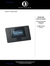
➃21-pin A/V cable with RGB connection
pin 1 = audio out, right channel
pin 2 = audio in, right channel
pin 3 = audio out, left channel
pin 4 = audio ground
pin 5 = blue ground
pin 6 = audio in, left channel
pin 7 = blue signal
pin 8 = 12V sense and Datalink
pin 9 = green ground
pin10 = data 2
pin11 = green signal
pin12 = data 1
pin13 = red ground
pin14 = fast blanking, ground
pin15 = red signal
pin16 = fast blanking
pin17 = video out, ground
pin18 = video in, ground
pin19 = video out, signal
pin20 = video in, signal
pin21 = shield, ground
1
2
3
6
4
15
13
11
9
7
5
16
18
20
17
19
8
21
10
12
14
21
19
17
15
20
18
16
13
11
14
12
9
7
10
8
6
54
32
1
2
1
6
3
4
15
13
11
9
7
5
16
17
19
18
20
8
21
10
12
14

MASTER CONTROL LINK
➄Coaxial cable
Run the coaxial cable direct to the
TV-set in the local room via an
aerial splitter or an aerial amplifier.
5

MASTER CONTROL LINK
6
PRODUCT DESCRIPTION
Below you will find a description of the individual elements included in
the BeoLink System as well as their scope of application.
Content
The X-tra speaker kit is used in those rooms where you wish to have
sound via passive speakers. The Beolink 1000 wall fixture is intended as a
storage place for the remote control terminal.
Application
Miscellaneous In addition to the content of the X-tra kit and the passive speakers, some
MCL cable and perhaps some plugs and connection boxes are required.
(See the section on installation types, page 27, for further information, if
required.)
When using the X-tra speaker kit the volume adjustment is common with
that in the Central room and any other X-tra speaker kits.
X-TRA SPEAKER KIT
The X-tra speaker kit contains an MCL 2A relay box, a transceiver, a
Beolink 1000 wall fixture and fittings for installation.

MASTER CONTROL LINK
Content
Application The X-tra active speaker kit is used in those rooms where you wish to have
sound through active speakers. The mains adaptor supplies power to the
MCL 2AV panel. The Beolink 1000 wall fixture is intended as a storage
place for the remote control terminal.
In addition to using the centrally placed audio and video systems via the
X-tra active speaker kit, it is possible to connect local sources (CD player
and tape recorder) to the MCL 2AV panel. Connection of local sources
allows you to listen to a CD player or a tape recorder independently of
the centrally placed products.
The X-tra active speaker kit has built-in “volume control”. This volume
control permits you to reduce the volume in the link room without
affecting the volume in other rooms. The volume can be increased by 12
dB in the link room without affecting the volume in other rooms. If the
volume is increased further, the volume in other rooms will be increased
comparatively.
In addition to the content of the X-tra kit and the active speakers, some
MCL cable and perhaps some plugs and connection boxes are required.
(See the section on installation types, page 27, for further information, if
required.)
Miscellaneous
7
X-TRA ACTIVE SPEAKER KIT
The X-tra active speaker kit contains an MCL 2AV panel, a transceiver, a
mains adaptor, a Beolink 1000 wall fixture as well as fittings for
installation.
REMEMBER When planning an installation, remember that both the active speakers
and the MCL 2AV panel have to be connected to the mains.

MASTER CONTROL LINK
Content
8
Application The X-tra TV kit is used in those rooms where you wish to have sound and
picture via a Bang & Olufsen TV set. The 7-pin AV cable forms the
connection between the MCL 2AV panel and the TV set. The mains
adaptor supplies power to the MCL 2AV panel. The Beolink 1000 wall
fixture is intended as a storage place for the remote control terminal.
In addition to using the centrally placed audio and video system via the X-
tra TV kit, it is possible to connect local sources (CD player and tape
recorder) to the MCL 2AV panel. Connection of local sources allows you
to listen to a CD player or a tape recorder independently of the centrally
placed products. In the link room with the X-tra TV kit, the volume can
be adjusted without affecting the volume in other rooms.
If the centrally placed audio system is set to a very low-volume starting
level, volume adjustment of the X-tra TV in the link room will have a
slight effect on the volume in other rooms.
In addition to the content of the X-tra kit and the TV set, some MCL cable
and perhaps some plugs and connection boxes are required.
(See the section on installation types, page 27, for further information, if
required).
Miscellaneous
REMEMBER When planning an installation, remember that both the TV set and the
MCL 2AV panel have to be connected to the mains.
X-TRA TV KIT
The X-tra TV kit contains an MCL 2AV panel, a mains adaptor, a 7-pin AV
cable, a Beolink 1000 wall fixture as well as fittings for installation.

MASTER CONTROL LINK 9
Content BeoLab 3500 (LCS 9000)
The BeoLab 3500 is an integrated link room speaker consisting of an
active speaker with Master Link (ML) connection, an IR receiver and a
display. BeoLab 3500 also has Master Control Link (MCL) connection.
Furthermore, the BeoLab 3500 has a built-in clock.
The BeoLab 3500 is supplied with a mains lead and a bracket for wall
mounting.
Application The BeoLab 3500 is used in link rooms where you wish to have an
integrated active speaker. From the BeoLab 3500 it is possible to listen to
all audio sources from the main room.
BeoLab 3500 has built-in sound control, meaning that tone and volume
can be adjusted independently of the main room.
With the tone control it is possible to adjust balance, bass, treble and
loudness individually.
BeoLab 3500 offers the following close-up operation features:
- Timer on/off
- PLAY / ST.BY
Part no. 1160111 (EU)
1160211 (GB)
1160311 (USA/CDN)
1160411 (JAP)
1160511 (AUS)
Miscellaneous Besides the parts included with the BeoLab 3500, the installation may
require a Master Control Link cable as well as plugs, sockets,cable covers
and connection boxes (see the section on installation types, page 27).

MASTER CONTROL LINK
Content
10
The IWS 2000 kit is for building-in in light partition walls, e.g.
plasterboard or wooden walls. The IWS 2000 kit is an integrated solution
with loudspeakers and MCL, where the X-tra speaker kit is mounted in
one of the IWS 2000 loudspeakers.
For further use, see X-tra speaker kit.
Application
REMEMBER As the wall dimensions and constructions vary considerably throughout
Europe, it is recommended that you make sure that the IWS 2000 is
suitable for mounting in your walls, before cutting the holes.
(See the IWS 2000 installation guide).
IWS 2000
The IWS 2000 kit consist of 2 Beovox IWS 2000 and an x-tra speaker kit.

MASTER CONTROL LINK 11
Content
Application BeoLink Converter is used when audio system and video products with
Master Link and Audio Aux Link (datalink) have to be interconnected.
BeoLink Converter can be used in conjunction with both a video and an
audiomaster. BeoLink Converter features autoconfiguration, meaning
that it is able to detect automatically whether it is installed in a Master
Link audio or in a Master Link video system. Configuration takes place
when it is connected to the mains.
BeoLink Converter is used in compatibility setups (see the section on
recommended compatibility setups, page 18).
1161466 (EU)
1161366 (USA/CDN)
BeoLink Converter
BeoLink Converter consists of a control box and a mains lead.
Part no.
Miscellaneous Besides the parts included with the BeoLink Converter, the installation
requires a Master Link cable/Maste Control Link cable as well as plugs,
sockets and junction boxes (see the section on installation types, page 27).

MASTER CONTROL LINK
12
Content
Application The AV 9000 Audio Kit is used to obtain compatibility between Beosystem
AV 9000 and products without Master Link connection (see the section on
recommended setups, Beosystem AV9000, page 17).
AV 9000 Audio Kit has been updated with a built-in power supply, and it
features autoconfiguration. The AV 9000 Audio Kit can be used in
conjunction with Beovision AV 9000 only.
Please note that the AV 9000 Audio Kit with switch cannot be used with
the new 9-pin Master Link cable.
AV 9000 Audio Kit
The AV 9000 Audio Kit consists of a control box and a mains lead.
Part no. 1161066
Miscellaneous Besides the parts included with the AV 9000 Audio Kit, the installation
requires a Master Link cable/Master Control Link cable as well as plugs,
sockets and junction boxes (see the section on installation types, page 27).

MASTER CONTROL LINK 13
Content
Application ML/MCL Converter is used where a conversion from Master Link (ML) to
Master Control Link (MCL) is wanted. Such a conversion is required if you
want to maintain the existing Master Control Link system although the
audio system in the main room is replaced with a Master Link driver, for
example a BeoSound Ouverture.
At the same time the ML/MCL converter replaces MCL 2P.
See setups with ML/MCL Converter, page 20.
Part no. Available from Nov. 1995.
1165166 (EU)
1165266 (GB)
1165366 (USA/CDN)
1165066 (AUS)
ML/MCL Converter
ML/MCL Converter consists of an amplifier including a control unit and a
mains lead.
Miscellaneous Besides the parts included with the ML/MCL Converter, the installation
requires a Master Link cable, a Master Control Link cable as well as plugs,
sockets and junction boxes (see the section on installation types, page 27).

MASTER CONTROL LINK
SETUPS
An object consisting of several parts can usually only be assembled in one
way if the intended result is to be achieved. For example, a gearbox for a
car will not perform optimally according to the specifications if you omit
installing some of the gearwheels. If you manage to instal one gearwheel
too many, that will be most likely to cause trouble as well.
The point of the above is that things must be put together in the way
they were designed to be put together if they are to perform optimally.
The same applies to Bang & Olufsen’s AV and BeoLink Systems. In theory,
Bang & Olufsen’s products may be connected in many thousands of
different ways. Since it would be totally impossible to have an overview
of just a fraction of this multitude of connection possibilities, Bang &
Olufsen has selected the most attractive combinations. These selected
combinations are called recommended setups. The recommended setups
are the ones which are focused on in connection with product
development and service.
When an AV system and/or a Master Control Link System is configured it is
therefore very important that this is done in accordance with the
recommended setups.
If the recommended setups are not followed, the result may easily be the
same as with the gearbox with too many or too few gearwheels.
Bang & Olufsen services the recommended setups ONLY.
Recommended setups
14
Option programming One of the conditions for the recommended setups to perform optimally
is that the products included in the setup “know” in what kind of
environment they are placed.
Are they standing alone (stand-alone products) or are they standing
together with other products. When option programming the products,
you “tell” them whether they are stand-alone products or they are
standing together with other products. After the option programming,
the products will perform optimally in the given setup.
The actual option programming is executed by pressing a certain
sequence of keys on the Beolink terminal.
For the Beolink 1000 terminal the key sequence is the following:
Beovision: “digit”
Beomaster: “digit”
Link room products: “digit”
Other products need not/cannot be option programmed.
The digit to be used depends on the setup.
See the illustrations on the following pages.

MASTER CONTROL LINK
For the Beo4 terminal the key sequence is the following:
Press and hold
then
Press to access the setup function. The Beo4 display reads
[OPTION?] - let go of both buttons
Press to access Option-programming
Press to display [V.OPT] BeoVision, or
[A.OPT] Beomaster/BeoSound, or
[L.OPT] link room products
then
Key in the number of the appropriate Option, e.g. 1
The digit sequence to be used depends on the setup.
Option 0 = No IR reception
Option 1 = Two IR-eyes in the same room
Option 2 = One IR-eye in the same room
Option 4 = Link room product connected to one or two main room products
It applies to most setups that they are delivered with the correct option
setting from the factory, and they are thus “ready for use”.
However, since in some situations you may have to work with products
that have been installed before, e.g. in connection with a house that has
been rebuilt, the correct option is indicated at ALL illustrations, even
those which are “ready for use” from the factory.
15
NOTE!
If the option programming is not executed
correctly, a malfunction will occur.

MASTER CONTROL LINK
16
Recommended AV systems
AV system in one room
Option programming Beovision : Ready for use
Factory setting Beovision : Option 1
Option programming Beomaster : Ready for use
Factory setting Beomaster : Option 1
AV system in two rooms
Option programming Beovision : Option 2
Factory setting Beovision : Option 1
Option programming Beomaster : Option 2
Factory setting Beomaster : Option 1

MASTER CONTROL LINK
Recommended AV 9000 Systems
17
2.
Option programming AV 9000 : Ready for use
Factory setting AV 9000 : Option 2
Option programming Beomaster : Option 0
Factory setting Beomaster : Option 1
AV 9000 Audiokit with one ML-socket : Ready for use
AV 9000 Audiokit with two ML-sockets : Switch in position 3
3.
Option programming AV 9000 : Option 1
Factory setting AV 9000 : Option 2
Option programming Beomaster : Ready for use
Factory setting Beomaster : Option 1
AV 9000 Audiokit with one ML-socket : Ready for use
AV 9000 Audiokit with two ML-sockets : Switch in position 2
AV system in one room
1.
Option programming AV 9000 : Ready for use
Factory setting setting AV 9000 : Option 2
Option programming Master Panel : Ready for use
Factory setting Master Panel : Option 2
AV system in two rooms
Option programming AV 9000 : Ready for use
Factory setting AV 9000 : Option 2
Option programming Beomaster : Option 2
Factory setting Beomaster : Option 1
AV 9000 Audiokit with one ML-socket : Ready for use
AV 9000 Audiokit with two ML-sockets : Switch in position 2
NOTE!
Information as to which Beomaster can be
connected to AV 9000 audio kit, see Bang &
Olufsen Product Configuration Guide.
/