Page is loading ...

i
K8T Neo
Version 1.1
G52-M6702X7
MS-6702 (v1.X) ATX Mainboard

ii
Manual Rev: 1.0
Release Date: September 2003
FCC-B Radio Frequency Interference Statement
This equipment has been tested and found to comply with the limits for a class
B digital device, pursuant to part 15 of the FCC rules. These limits are designed
to provide reasonable protection against harmful interference when the equip-
ment is operated in a commercial environment. This equipment generates, uses
and can radiate radio frequency energy and, if not installed and used in accor-
dance with the instruction manual, may cause harmful interference to radio
communications. Operation of this equipment in a residential area is likely to
cause harmful interference, in which case the user will be required to correct
the interference at his own expense.
Notice 1
The changes or modifications not expressly approved by the party respon-
sible for compliance could void the user’s authority to operate the equipment.
Notice 2
Shielded interface cables and A.C. power cord, if any, must be used in order to
comply with the emission limits.
VOIR LA NOTICE D’INSTALLATION AVANT DE RACCORDER AU
RESEAU.
Micro-Star International MS-6702
Tested to comply
with FCC Standard
For Home or Office Use

iii
Copyright Notice
The material in this document is the intellectual property of MICRO-STAR
INTERNATIONAL. We take every care in the preparation of this document,
but no guarantee is given as to the correctness of its contents. Our products
are under continual improvement and we reserve the right to make changes
without notice.
Trademarks
All trademarks are the properties of their respective owners.
Intel
®
and Pentium
®
are registered trademarks of Intel Corporation.
AMD, Athlon™, Athlon™ XP, Thoroughbred™, and Duron™ are registered
trademarks of AMD Corporation.
PS/2 and OS
®
/2 are registered trademarks of International Business Machines
Corporation.
Windows
®
95/98/2000/NT/XP are registered trademarks of Microsoft
Corporation.
Netware
®
is a registered trademark of Novell, Inc.
Award
®
is a registered trademark of Phoenix Technologies Ltd.
AMI
®
is a registered trademark of American Megatrends Inc.
Revision History
Revision Revision History Date
V1.0 First release August 2003
V1.1 Add appendix A/B September 2003
Ch2 add front panel LED signal
description
Technical Support
If a problem arises with your system and no solution can be obtained from the
user’s manual, please contact your place of purchase or local distributor.
Alternatively, please try the following help resources for further guidance.
Visit the MSI website for FAQ, technical guide, BIOS updates, driver
updates, and other information: http://www.msi.com.tw/
Contact our technical staff at: [email protected]

iv
1. Always read the safety instructions carefully.
2. Keep this User’s Manual for future reference.
3. Keep this equipment away from humidity.
4. Lay this equipment on a reliable flat surface before setting it up.
5. The openings on the enclosure are for air convection hence protects the
equipment from overheating. DO NOT COVER THE OPENINGS.
6. Make sure the voltage of the power source and adjust properly 110/220V
before connecting the equipment to the power inlet.
7. Place the power cord such a way that people can not step on it. Do not
place anything over the power cord.
8. Always Unplug the Power Cord before inserting any add-on card or module.
9. All cautions and warnings on the equipment should be noted.
10. Never pour any liquid into the opening that could damage or cause electri-
cal shock.
11. If any of the following situations arises, get the equipment checked by a
service personnel:
z The power cord or plug is damaged.
z Liquid has penetrated into the equipment.
z The equipment has been exposed to moisture.
z The equipment has not work well or you can not get it work according
to User’s Manual.
z The equipment has dropped and damaged.
z The equipment has obvious sign of breakage.
12. DO NOT LEAVE THIS EQUIPMENT IN AN ENVIRONMENT
UNCONDITIONED, STORAGE TEMPERATURE ABOVE 60
0
C (140
0
F), IT
MAY DAMAGE THE EQUIPMENT.
Safety Instructions
CAUTION: Danger of explosion if battery is incorrectly replaced.
Replace only with the same or equivalent type recommended by the
manufacturer.

v
CONTENTS
FCC-B Radio Frequency Interference Statement ..........................................iii
Copyright Notice ..........................................................................................iii
Revision History ...........................................................................................iii
Technical Support ......................................................................................... iii
Safety Instructions ....................................................................................... v
Chapter 1. Getting Started ........................................................................ 1-1
Mainboard Specifications ....................................................................1-2
Mainboard Layout ...............................................................................1-4
MSI Special Features ...........................................................................1-5
Color Management ........................................................................1-5
Core Center....................................................................................1-6
Core Cell™ Chip ............................................................................1-9
Dynamic Overclocking Technology ............................................ 1-10
Live BIOS™/Live Driver™ .......................................................... 1-11
Live Monitor™ ............................................................................ 1-12
D-Bracket™ 2 (Optional) ............................................................. 1-13
Chapter 2. Hardware Setup ....................................................................... 2-1
Quick Components Guide ....................................................................2-2
Central Processing Unit: CPU ..............................................................2-3
CPU Installation Procedures for Socket 754 ..................................2-4
Installing AMD Athlon64 CPU Cooler Set ....................................2-5
Memory................................................................................................2-9
Introduction to DDR SDRAM....................................................... 2-9
DDR DIMM Module Combination .............................................. 2-10
Installing DDR Modules ............................................................. 2-10
Recommended Memory Combination List .................................. 2-11
Power Supply ..................................................................................... 2-12
ATX 20-Pin Power Connector: ATX ............................................ 2-12
ATX 12V Power Connector: JPW1 .............................................. 2-12

vi
Back Panel .......................................................................................... 2-13
Mouse Connector ....................................................................... 2-13
Keyboard Connector ................................................................... 2-13
USB 2.0 Connectors .................................................................... 2-14
IEEE1394 Ports (Optional) ........................................................... 2-14
Serial Port Connector: COM A .................................................... 2-15
RJ-45 LAN Jack (Optional) .......................................................... 2-15
Audio Port Connectors ............................................................... 2-16
Parallel Port Connector: LPT1...................................................... 2-17
Connectors......................................................................................... 2-18
Floppy Disk Drive Connector: FDD1........................................... 2-18
IrDA Infrared Module Header: JIR1 ............................................ 2-18
Chassis Intrusion Switch Connector: JCASE1 ............................ 2-18
Fan Power Connectors: CFAN1/SFAN1/PWFAN1/PWFAN2 ..... 2-19
Front USB Connectors: JUSB1/JUSB2 ........................................ 2-19
Front Panel Connectors: JFP1 & JFP2 ......................................... 2-20
CD-In Connector: J4 .................................................................... 2-20
Hard Disk Connectors: IDE1 & IDE2 ........................................... 2-21
Power Saving Switch Connector: JGS1........................................ 2-21
Serial ATA/Serial ATA RAID Connectors controlled by VT 8273: IDE3,
SER1, SER2 . ................................................................................. 2-22
Serial ATA/Serial ATA RAID Connectors controlled by Promise 20378:
SATA1, SATA2 ........................................................................... 2-22
Front Panel Audio Connectors: JAUD1 ...................................... 2-24
D-Bracket™ 2 Connector: JLED (Optional) ................................. 2-25
Jumper ................................................................................................ 2-26
Clear CMOS Jumper: JBAT1 ........................................................ 2-26
Slots ................................................................................................... 2-27
AGP (Accelerated Graphics Port) Slot......................................... 2-27
PCI (Peripheral Component Interconnect) Slots.......................... 2-27
PCI Interrupt Request Routing .................................................... 2-28

vii
Chapter 3. BIOS Setup.............................................................................. 3-1
Entering Setup......................................................................................3-2
Selecting the First Boot Device .....................................................3-2
Control Keys ................................................................................. 3-3
Getting Help ..................................................................................3-3
The Main Menu ...................................................................................3-4
Standard CMOS Features .................................................................... 3-6
Advanced BIOS Features ....................................................................3-8
Advanced Chipset Features............................................................... 3-12
Power Management Features............................................................. 3-15
PNP/PCI Configurations..................................................................... 3-19
Integrated Peripherals ........................................................................ 3-21
PC Health Status ................................................................................ 3-24
Frequency/Voltage Control ................................................................ 3-25
Set Supervisor/User Password........................................................... 3-27
Load High Performance/BIOS Setup Defaults.................................... 3-28
AppendixA. Using 4- or 6-Channel Audio Function .................................A-1
AppendixB. VIA VT8237 Serial ATA RAID Introduction ........................B-1

1-1
Getting Started
Chapter 1. Getting
Started
Thank you for purchasing K8T Neo (MS-6702 v1.X) ATX
mainboard. The K8T Neo is based on VIA
®
K8T800 North Bridge
& VT8237 South Bridge chipsets and provides eight USB 2.0
ports for high-speed data transmission, RealTek ALC655 chip for
6-channel audio output, and a SPDIF interface for digital audio
transmission. Designed to fit the advanced AMD
®
Athlon64
processors, the K8T Neo delivers a high performance and profes-
sional desktop platform solution.
Getting Started

1-2
MS-6702 ATX Mainboard
Mainboard Specifications
CPU
h Supports 64-bit AMD
®
Athlon64 processor (Socket 754)
h Supports up to 3200+, 3400+, or higher CPU
Chipset
h VIA
®
K8T800 chipset
- HyperTransport
TM
connection to AMD Athlon64 processor
- 8 or 16 bit control/address/data transfer both directions
- 800/600/400/200 MHz “Double Data Rate” operation both direction
- AGP v3.0 compliant with 8x transfer mode
h VIA
®
VT8237 chipset (487 BGA)
- Integrated Faster Ethernet LPC
- Integrated Hardware Sound Blaster/Direct Sound AC97 audio
- Ultra DMA 66/100/133 master mode PCI EIDE controller
- ACPI
- Supports 2 Serial ATA ports
- Supports 8 USB2.0 ports
Main Memory
h Supports DDR266/333/400 DDR SDRAM for three 184-pin DDR DIMMs
h Supports a maximum memory size of 2GB
Slots
h One (Accelerated Graphics Port) AGP slot.
- AGP 3.0 specification compliant
hFive 32-bit Master 3.3v / 5v PCI Bus slots
On-Board IDE
h An IDE controller on the VIA® VT8237 chipset provides IDE HDD/CD-
ROM with PIO, Bus Master and Ultra DMA 66/100/133 operation modes
h Can connect up to 4 IDE devices
h Serial ATA/150 controller integrated by VT8237
- Up ot 150MB/s transfer rate
- Can connect up to 2 serial ATA devices
IEEE 1394 (Optional)
h Supports up to 2 * 1394 ports. Transfer rate is up to 400Mbps
h Controlled by VIA 6307 chipset

1-3
Getting Started
Promise 20378 On-Board (Optional)
h Supports 2 serial ATA plus 1 ATA133
- RAID 0, RAID 1 or RAID 0+1 is supported
- RAID function work w/ATA133+SATA H/D or 2SATA H/D
h Connect up to 2 SATA device and 2 ATA133 devices
On-Board Peripherals
h On-Board Peripherals include:
- 1 floppy port supports 2 FDDs with 360K, 720K, 1.2M, 1.44M and
2.88Mbytes
- 1 serial port (COMA)
- 1 parallel port supports SPP/EPP/ECP mode
- 1 IrDA connector for SIR/ASKIR/HPSIR
- 1 audio port
- 1 D-Bracket2 pinheader
Audio
h 6 channels software audio codec RealTek ALC655.
- Compliance with AC97 v2.3 Spec.
- Meet PC2001 audio performance requirement.
LAN 10/100/1000Mbps
h
RealtekRealtek
RealtekRealtek
Realtek
® ®
® ®
®
8110C/8110S Dual layout. 8110C/8110S Dual layout.
8110C/8110S Dual layout. 8110C/8110S Dual layout.
8110C/8110S Dual layout.
- Integrated Fast Ethernet MAC and PHY in one chip.- Integrated Fast Ethernet MAC and PHY in one chip.
- Integrated Fast Ethernet MAC and PHY in one chip.- Integrated Fast Ethernet MAC and PHY in one chip.
- Integrated Fast Ethernet MAC and PHY in one chip.
- Supports 10Mb/s, 100Mb/s and 1000Mb/s (1000Mb/s only for Realtek- Supports 10Mb/s, 100Mb/s and 1000Mb/s (1000Mb/s only for Realtek
- Supports 10Mb/s, 100Mb/s and 1000Mb/s (1000Mb/s only for Realtek- Supports 10Mb/s, 100Mb/s and 1000Mb/s (1000Mb/s only for Realtek
- Supports 10Mb/s, 100Mb/s and 1000Mb/s (1000Mb/s only for Realtek
8110S)8110S)
8110S)8110S)
8110S)
BIOS
h The mainboard BIOS provides “Plug & Play” BIOS which detects the pe-
ripheral devices and expansion cards of the board automatically.
h The mainboard provides a Desktop Management Interface (DMI) function
which records your mainboard specifications.
h ACPI, 1.0a, APM1.2, PnP 1.0a, SMBIOS 2.3, USB 2.0, WFM 2.0, Overclock,
Boot from USB device.
Dimension
h ATX Form Factor: 30.5 cm (L) x 24.5 cm (W).
Mounting
h 9 mounting holes.

1-4
MS-6702 ATX Mainboard
Mainboard Layout
MS-6702 v1.X ATX Mainboard
BATT
+
VIA
K8T800
D
D
R
1
D
D
R
2
D
D
R
3
A
T
X
P
o
w
e
r
S
u
p
p
l
y
JUSB1
JUSB2
JAUD1
J4
PCI Slot 5
PCI Slot 4
PCI Slot 3
PCI Slot 2
PCI Slot 1
I
D
E
1
IDE 3
I
D
E
2
JGS1
J
B
A
T
1
JP1
J
C
A
S
E
1
JLED
JFP1JFP2
SER1
SATA1
SATA2
SER2
To p : L AN j a ck
Bottom: USB ports
To p : P a r a lle l P ort
Bottom:
1394 port
Mini 1394 port
Top : mouse
Bottom: keyboard
SFAN1
JIR1
JPW1
CFAN1
PWFAN2
PWFAN1
Winbond
W83697HF
RealTek
8110S
PROMISE
PDC20378
VIA
VT6307
Codec
T:
M:
B:Mic
Line-In
Line-Out
T:
M:
B:SPDIF Out
Line-Out
Line-Out
F
D
D
1
BIOS
AGP Slot
VIA
VT8237
T: SP DI F Ou t
B: USB ports

1-5
Getting Started
MSI Special Features
Color Management
MSI has a unified color management rule for some connectors on the
mainboards, which helps you to install the memory modules, expansion cards
and other peripherals devices more easily and conveniently.
h Memory DDR DIMMs: Light Green
h Intel spec IDE ATA66/100/133 connector: Yellow
h IDE ATA133 connector: Yellow
h Serial ATA connectors: Orange
h AGP 8X slot: Red
h USB 2.0 connector: Blue
h Front panel connector JFP1 : HDD LED in Red, Reset Switch in Blue,
Power Switch in Black, Power LED in Light Green.
h Front panel connector JFP2: Power LED in Light Green.
Memory DDR DIMMs
Front Panel connector JFP2
USB 2.0 connector
AGP 8X Slot
Intel spec IDE ATA66/100/133
connectors
Front Panel connector JFP1
Serial ATA connectors
Serial ATA connectors
IDE ATA133 connector

1-6
MS-6702 ATX Mainboard
Core Center
The Core Center is a new utility you can find in the CD-ROM disk. The
utility is just like your PC doctor that can detect, view and adjust the PC
hardware and system status during real time operation.
Cool’n’Quiet
This utility provides a CPU temperature detecting function called
Cool’n’Quiet. Cool’n’Quiet is a special feature designed only for AMD
®
Athlon64 processor, and with Cool’n’Quiet, the system will be capable of
detecting the temperature of the CPU according to the CPU’s working loading.
When the CPU temperature climbs up to a certain degree, the speed of the
system cooling fan will be risen automatically, and on the other hand, the
speed of the system cooling fan will dorp instantly when the CPU temperature
descends to its normal degree.
To activate Cool’n’Quiet function, please click the Core Center
Cool’n’Quiet icon, and then select Cool’n’Quiet mode. If User mode is selected,
you will be able to adjust the CPU fan speed by sliding the adjusting bar.

1-7
Getting Started
In addition to Cool’n’Quiet setting, the current system status (including
Vcore, 3.3V, +5V and 12V) and the current PC hardware status (such as the CPU
& system temperatures and all fans speeds) are also shown on the left and
right sides.
When you click the red triangles in the left and right sides, two sub-
menus will open for users to overclock, overspec or to adjust the thresholds of
system to send out the warning messages.
Left-side: Current system status
In the left sub-menu, you can configure the settings of FSB, Vcore,
Memory Voltage and AGP Voltage by clicking the radio button in front of each
item and make it available (the radio button will be lighted as yellow when
selected), use the “+” and “-” buttons to adjust, then click OK to apply the
changes. Then you can click Save to save the desired FSB you just configured.
Also you may click Auto to start testing the maximal CPU overclocking
value, The CPU FSB will automatically increase the testing value until the PC
reboots. Or you may click Default to restore the default values.
Right-side: PC hardware status during real time operation
In the right sub-menu, here you can configure the PC hardware status
such as CPU & system temperatures and fan speeds. You may use the scroll
bars to adjust each item, then click
““
““
“OK
””
””
” to apply the changes. The values you
set for the temperatures are the maximum thresholds for the system for warnings,
and the values for fan speeds are the minimum thresholds.

1-8
MS-6702 ATX Mainboard
MSI Reminds You...
To ensure that Cool’n’Quiet function is activated and will be
working properly, it is required to double confirm that:
1. Check the serial number printed on the top of CPU. On the
top of CPU, there are three lines listed under AMD Athlon
TM
.
Find the 13 characters of the first line, and locate the last one
from those 13 characters. If the last character is “O” or after
“O” (such as P, Q, R, and so on), that means this CPU supports
Cool’n’Quiet function. On the contrary, if the last character
is before “O”, that means this CPU does not support
Cool’n’Quiet function.
2. Run BIOS Setup, and select Frequency/Voltage Control.
Under Frequency/Voltage Control, find Cool’n’Quiet
Support, and set this item to “Enable.”
3. Enter Windows, and select [Start/Settings/Control Pannel/
Power Options.] Enter Power Options Properties tag, and
select Minimal Power Management under Power schemes.

1-9
Getting Started
BuzzFree
-- Diagnoses current sys-
tem utilization &
temperature.
-- Controls both CPU and
NorthBridge fans.
-- Cuts up to 50% of sys-
tem noise.
PowerPro
-- Saves up to 65% power.
-- Assures motherboard
stability.
-- Empowers O.C Capability.
Speedster
-- Advanced O.C. design.
-- Superior O.C. capability.
-- Greater O.C. method.
Features of CoreCell™
Core Cell
TM
Chip
By diagnosing the current system utilization, the
CoreCell™ Chip automatically tunes your motherboard to the
optimal state, leading to less noise, longer duration, more power-
saving and higher performance.
LifePro
-- Prolongs motherboard, CPU and fan life.
-- Maintains motherboard & CPU in constant temperature.
-- Prevents components from operating beyond specifications.

1-10
MS-6702 ATX Mainboard
Dynamic Overclocking Technology
Dynamic Overclocking Technology is the automatic overclocking
function. It is designed to detect the load balance of CPU while running
programs, and to adjust the best CPU frequency automatically. When the
motherboard detects CPU is running programs, it will speed up CPU
automatically to make the program run smoothly and faster. When the CPU is
temporarily suspending or staying in the low load balance, it will restore the
default settings instead. Usually the Dynamic Overclocking Technology will
be powered only when users' PC need to run huge amount of data like 3D
games or the video process, and the CPU frequency need to be boosted up to
enhance the overall performance.
MSI Reminds You...
Even though the Dynamic Overclocking Technology is more
stable than manual overclocking, basically, it is still risky. We
suggest user to make sure that your CPU can afford to
overclocking regularly first. If you find the PC appears to be
unstable or reboot incidentally, it's better to disable the Dy-
namic Overclocking or to lower the level of overclocking options.
By the way, if you need to conduct overclocking manually, you
also need to disable the Dynamic OverClocking first.
D.O.T
Dynamic Overclocking Technology
D.O.T

1-11
Getting Started
Live BIOS™/Live Driver™
The Live BIOS™/Live Driver™ is a tool used to detect
and update your BIOS/drivers online so that you don’t need to
search for the correct BIOS/driver version throughout the whole
Web site. To use the function, you need to install the “MSI
Live Update 3” application. After the installation, the “MSI
Live Update 3” icon (as shown on the right) will appear on the
screen.
Double click the “MSI Live Update 3” icon, and the following screen will
appear:
Five buttons are placed on the left column of the screen. Click the desired
button to start the update process.
Ø Live BIOS – Updates the BIOS online.
Ø Live Driver – Updates the drivers online.
Ø Live VGA BIOS – Updates the VGA BIOS online.
Ø Live VGA Driver – Updates the VGA driver online.
Ø Live OSD – Updates the firmware of the OSD products online.
Ø Live Utility – Updates the utilities online.
If the product you purchased does not support any of the functions listed
above, a “sorry” message is displayed. For more information on the update
instructions, insert the companion CD and refer to the “Live Update Guide”
under the “Manual” Tab.

1-12
MS-6702 ATX Mainboard
Live Monitor™
The Live Monitor™ is a tool used to schedule the search
for the latest BIOS/drivers version on the MSI Web site. To use
the function, you need to install the “MSI Live Update 3”
application. After installation, the “MSI Live Monitor” icon (as
shown on the right) will appear on the screen. Double click this
icon to run the application.
Double click the “MSI Live Monitor” icon at the lower-right corner
of the taskbar, and the following dialog box will appear. You can specify how
often the system will automatically search for the BIOS/drivers version, or
change the LAN settings right from the dialog box.
You can right-click the MSI Live Monitor icon to perform the functions
listed below:
zz
zz
z Auto Search – Searches for the BIOS/drivers version you need immediately.
zz
zz
z View Last Result – Allows you to view the last search result if there is any.
zz
zz
z Preference – Configures the Search function, including the Search schedule.
zz
zz
z Exit – Exits the Live Monitor™ application.
zz
zz
z FAQ – Provides a link to a database which contains various possible questions
about MSI's products for users to inquire.

1-13
Getting Started
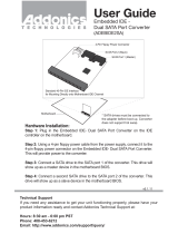
D-Bracket™ 2
1 2
3 4
D-Bracket™ 2 (Optional)
D-Bracket™ 2 is an external USB bracket integrating four Diagnostic
LEDs, which use graphic signal display to help users understand their system.
The LEDs provide up to 16 combinations of signals to debug the system. The
4 LEDs can debug all problems that fail the system, such as VGA, RAM or
other failures. This special feature is very useful for the overclocking users.
These users can use the feature to detect if there are any problems or failures.
D-Bracket™ 2 supports both USB 1.1 & 2.0 specification.
Red
Green
Description
System Power ON
- The D-LED will hang here if the processor is dam-
aged or not installed properly.
Early Chipset Initialization
Memory Detection Test
- Testing onboard memory size. The D-LED will hang
if the memory module is damaged or not installed
properly.
Decompressing BIOS image to RAM for fast booting.
1 2
3 4
Initializing Keyboard Controller.
Testing VGA BIOS
- This will start writing VGA sign-on message to the
screen.
D-Bracket™ 2
/