BCS 722 Owner's manual

Category
Garden shredders
Type
Owner's manual

This manual is also suitable for

POWER UNITS
& Gardening Attachments
OWNERS
USE & CARE
MANUAL
CODE NUMBER 90103079 EDITION 01.11
M
O
D
E
L
S
NEW HANDLEBARS
710
GARDENER
712
RENTAL
718
HARVESTER
722
HARVESTER
732
PROFESSIONAL
948
PROFESSIONAL
852
PROFESSIONAL
853
PROFESSIONAL
Dear Customer,
Thank you for your purchase. Get set to enjoy the benefits your wise
selection of a BCS unit has earned for you. We believe that no other
make machine that can handle so many lawn and garden tasks with
such fine results – and with so little effort on your part.
Your BCS unit has precision gearing for lasting, trouble-free service.
There are no drive belts to stretch and break.
Our network of BCS distributors and servicing dealers stands ready to
supply tour needs for attachments, accessories, parts and service.
With a yearly check-up, your dealer can help you keep your BCS
equipment to shape. Meanwhile, be sure to follow the operating and
maintenance tips in this owner’s manual for satisfied performance of
your machine.
BCS America
MODELS IN THIS EDITION
BCS America maintains a dynamic updating poli-
cy. If notifies the field of the serial number of the
first unit off the line after a change.
This edition covers the models and model options
listed in the specifications on page 16.
A
ccordingly, be sure to record the BCS unit serial
number printed between two stars on the tran-
smission, and the engine model and serial num-
bers from the engine name plate.
GRAPHIC SYMBOL
THIS SYMBOL IS LIKE A FLAG.
IT FLAGS YOUR ATTENTION TO DANGER WARNINGS IN THE MANUAL.
WHEN PLACED OVER A PICTURE OR AN ITEM IN THE PICTURE, THIS SYMBOL SAYS
“NO !” DO NOT DO, OR USE OR PERMIT WHATEVER IS SHOWN.
WARNING
READ ALL SAFETY RULES AND OPERATING AND MAINTENANCE
INSTRUCTIONS IN THIS MANUAL BEFORE USING ANY POWER UNIT,
ATTACHMENT, OR ACCESSORY.
2
CONTENTS
SECTION ONE
RULES FOR SAFE OPERATION
OF UNIT AND ATTACHMENTS
SECTION TWO
SCHEME CONFIGURATIONS
SECTION THREE
USE AND CARE OF ATTACHMENTS
GENERAL PRECAUTIONS AND INSTRUCTIONS
REAR-TINE TILLER PRECAUTIONS
ROTARY MOWER PRECAUTIONS
CUTTER BAR MOWER PRECAUTIONS
SNOW THROWER PRECAUTIONS
POWER SPRAYER PRECAUTIONS
CHIPPER/SHREDDER PRECAUTIONS
POWER SWEPPER PRECAUTIONS
MODELS DESIGNED FOR FRONT-MOUNTED ATTACHMENTS
MODELS DESIGNED FOR REAR-MOUNTED ATTACHMENTS
SPECIFICATIONS
MODEL 852, 853
MODELS 710, 712
MODELS 718, 722, 732
MODEL 948
UNPACKING
ASSEMBLING THE UNIT
LUBRICATION FILTER AND FUEL
ENGINE CRANKCASE LUBRICATION
GEARBOX LUBRICATION
ENGINE AIR CLEANER
GASOLINE ENGINE FUEL
STARTING AND STOPPING
SETTING CONTROLS FOR COLD STARTING
CRANKING TO START
STOPPING
DIFFERENTIAL AND TWO-WHEEL DRIVE
WHEEL BRAKES
SHUT-DOWN (STORAGE)
TAKING CONTROL OF THE MACHINE
GEAR AND P.T.O. ENGAGEMENT
MAKING A CONVERSION FRONT-TO-REAR, OR REAR-TO-FRONT
OPERATING IN CONVERTED MODE
MAINTENANCE PROGRAM
LUBRICATION OF ATTACHMENTS
COUPLING ATTACHMENT TO P.T.O.
USE AND CARE OF REAR-TINE TILLER
PREPARING NEW TILLER
WIDTH OF TILTH
TILLING DEPTH ADJUSTMENT
GARDENING SUGGESTIONS
TRANSPORT SULKY FOR REAR-TINE TILLER
USE AND CARE OF CUTTER BAR MOWER ATTACHMENT
GENERAL CUTTER BAR MOWER INFORMATION
RECOMMENDED OPERATION
MOWER BAR MAINTENANCE
USE AND CARE OF 2-BLADE ROTARY MOWER
THE UNITS CONVERTED FOR MOWER USE
ASSEMBLY, CONNECTION AND LEVELING OF THE 2-BLADE MOWER
LUBRICATION
ROTARY MOWER OPERATION
INSPECTION AND MAINTENANCE
USE AND CARE OF SNOW THROWERS
GENERAL INFORMATION
SNOW THROWER OPERATION
USE AND CARE OF CHIPPER / SHREDDER
CHIPPER / SHREDDER MAINTENANCE
USE AND CARE OF POWER SWEEPER
OPERATION
MAINTENANCE AND STORAGE
USE AND CARE OF DOZER BLADE
Page 5
8
9
10
10
11
12
13
15
15
16
17
18
19
20
21
21
25
25
25
26
27
28
29
30
30
30
30
31
31
31
32
33
35
36
36
37
37
37
37
38
38
39
39
39
39
41
41
41
42
42
43
44
44
44
45
45
46
46
46
47
3
RECORD OF SERIAL NUMBERS .
BCS UNIT SERIAL NUMBER * __________ *
(Located between stars on transmission)
BRIGGS & STRATTON
ENGINE SERIAL NUMBER __________
(Stamped on crankcase about two inches from
name plate on side of engine)
HONDA ENGINE SERIAL NUMBER:
TYPE _____________
SERIAL N
O
. ____________
LOMBARDINI ENGINE SERIAL NUMBER ____________________ (Located on engine name plate)
WARNING
READ ALL SAFETY RULES AND OPERATING AND MAINTENANCE
INSTRUCTIONS IN THIS MANUAL BEFORE USING ANY POWER UNIT,
ATTACHMENT, OR ACCESSORY.
4
SECTION
INSTRUCTIONS FOR SAFE OPERATION OF
BCS POWER UNITS AND ATTACHMENTS
General precautions and instructions are followed by specific precautions
for each combination of attachment and power unit in the owner’s manual.
GENERAL PRECAUTIONS AND
INSTRUCTIONS .
TRAINING
READ THIS OWNER'S MANUAL PRIOR TO OPERATING THE
POWER UNITS AND ATTACHMENTS.
BCS power units and attachments are designed for operation by pro-
perly instructed adults only. Make certain that any person operating
this equipment has read this manual.
DO NOT LET CHILDREN OPERATE THE POWER UNIT.
KEEP THE OPERATING AREA CLEAR OF PEOPLE AND ANI-
MALS. BE CAREFUL THAT CHILDREN DO NOT COME NEAR.
During storage, and whenever the power unit is unattended, disen-
gage the PTO (power take-off) and render the engine unstartable by
disconnecting the spark plug wire from spark plug.
PREPARATION
Wear appropriately protective clothing and safety protection articles
for the climate and type of attachment you are to operate.
1. For all walk-behind applications, wear sturdy non-slip boots or sa-
fety toe shoes. See recommendations listed for use of a particular
attachment. Do not wear open-toed sandals or go barefoot when
operating these machines.
2. Wear snug-fitting protective clothing which allows freedom of mo-
vement without being loose-fitting. Ties, scarf and jewels which
could be caught in the machinery should not be worn.
3. Wear hearing protection.
4. Wear eye protection when operating a snow-thrower, power spra-
yer, chipper / shredder or mower attachment.
5.
Overexposure to sunlight can be damaging to your eyes and skin.
When working in strong sunlight, protect your eyes with sun glas-
ses and either keep your body covered or apply a sun screen
lotion.
Do not operate on terrain where you cannot maintain good footing or
where the machine could overturn or slide into you. When walking
behind the unit, walk slowly. DO NOT RUN!
5
1
Thoroughly inspect the area where you are going to mow or
thatch the lawn, sweep walks or drives or throw snow. Remo-
ve toys, stones, bones, wires, glass, newspapers and other
objects which could be caught up and thrown by the machine.
Take the following precautions for the safe handling and sto-
rage of fuel:
1.
Keep fuel supplies in approved type, properly labelled fuel
containers.
2.
Do not store fuels or fuelled units in closed (unventilated)
areas or in garages or shops connected to human living quar-
ters. Do not store units or fuel where there are flames or sour-
ces of sparks such as electrical appliances and switches.
3. Obey all local regulations for the storage and handling of
fuel.
4. Do not smoke when fuelling, or fuel where the fumes could
be ignited by fire or sparks.
5. Do all fuelling outdoors over non-flammable surfaces. If fuel
is spilled on the unit, wipe the unit dry and properly dispose of
the wiping rag. ALWAYS MOVE THE UNIT AT LEAST 10
FEET (3 m.) AWAY from the fuelling spot and fuel supplies be-
fore starting the engine.
6. Always remove the engine fuel cap very slowly to equalize
tank pressure and avoid spurting of fuel. Keep your face and
eyes away from the tank while loosening the fuel cap.
7. Do not fuel a running or hot engine. Do not loosen the fuel
cap until the engine has stopped.
Then wait several minutes for the engine to cool before pou-
ring fuel. Before starting the engine, put all control levers in
neutral (N) position. All "N" positions on the gear selector are
neutral. Also be sure to disengage the PTO (power take-off) to
the attachment. Never make blade height or any other adjust-
ment to the power unit or any attachment while the engine is
running.
OPERATION
Operate only when there is good visibility. Do not operate at
dusk or at night. Do not operate when it is foggy or hazy.
Never change the engine governor setting or overspeed the
engine. Use the throttle and gear settings recommended for
particular attachments and applications in this owner's manual.
Do not put hands and feet under the mower deck or into the
discharge openings of a rotary mower.
Do not put fingers or any other part of the body into the intake
or discharge openings of any mower, snow-thrower or chipper/
shredder unless you have disconnected the spark plug wire so
engine cannot be started accidentally.
Keep the machine clean-out holes closed. Stay out of the dis-
charge stream of a mower, chipper/shredder, power sweeper
or power sprayer.
Always stop operation of a rotary mower, a cutter bar mower,
snow thrower or a tiller before crossing paved or gravel road-
ways.
6
2 1
Never ride the tractor or an attachment. Ride only on ri-
ding accessories designed for the purpose. Do not take
children on a sulky with you.
1. Use transport sulkies only for transport to and from
the operating area and never for operation.
2. Use utility wagons only for hauling and limit the pay-
load to the rated capacity of the wagon.
3. A mowing sulky is exclusively for operation of a rota-
ry mower and must not be used with any other attach-
ment.
4. Never use ride-on attachments on the highway or
any city street.
Do not disconnect or otherwise defeat the purpose of
the lockout devices.
The high-speed lockout prevents using too fast a gear
for backing up a front-mounted attachment.
The PTO/REVERSE lockout permits backing up a rear-
mounted attachment only when the PTO is disengaged.
Read Section Two for explanation of the lockout devi-
ces.
Do not use the highest numbered gear on the gear se-
lector when walking behind the machine.
On all units in this manual, the highest gear produces
much faster than walking speed and is only to be used
for transport in conjunction with a transport sulky.
Don't make adjustments or repairs to the machine when
the engine is running.
Put all controls in neutral, wait until reciprocating or rota-
ting parts of the attachment have stopped and discon-
nect the spark plug wire:
1. Before leaving the unit where unauthorized persons
may start it accidentally.
2. When a foreign object has been struck or taken into
the attachment. Proper operation should be restored be-
fore further use.
3. Before cleaning out a clogged attachment such as a
rotary mower, cutter bar mower, snow-thrower, chipper/
shredder or power sweeper.
4. If the machine suddenly starts to vibrate or run erra-
tically. The entire machine should be inspected by an
authorized BCS servicing dealer before further use.
All safety guards, plates, lockouts, deflectors and shields
must be in proper position.
Do not operate if any safety devices or fastening parts
are missing from the unit.
Do not run the engine indoors where deadly poisonous
carbon monoxide fumes can collect.
If the engine is to be started inside a garage or barn,
open the doors and windows wide so the fumes can
escape.
7
21
MAINTENANCE AND STORAGE
Keep engine, tractor and all attachments in safe working condi-
tion. Clean the unit and accessories at regular intervals, also
check for damaged or missing parts.
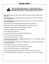
Check the tightness of all fasteners. Perform the items of mainte-
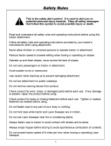
nance recommended in this owner’s manual. Do not attempt any
disassembly and repairs for which instructions have not been
furnished.
Certain engine adjustments, and interval servicing of the engine,
tractor, clutch and transmission, and gearboxes of attachments
should be done only by a BCS-trained service-man at an autho-
rized BCS servicing dealer or distributor.
Do not store the machine with fuel in the system. Disconnect the
fuel line at the carburettor inlet, and drain the fuel into a fuel
container. Then reconnect the fuel line. Start and run the engine
until it stops from lack of fuel.
When storing the machine, use the spring latch (illustra-
ted on page 29) to latch the clutch lever in the depressed
(disengaged) position. This prevents the clutch cone from
sticking to the lining during storage.
Store the machine in a well-ventilated place, protected from
dampness and the weather.
REAR-TINE TILLER
PRECAUTIONS .
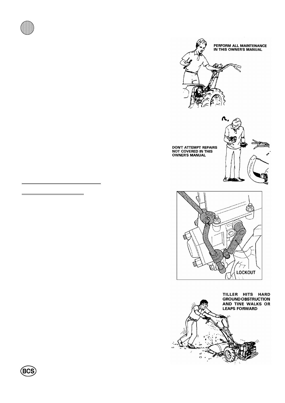
All the models have PTO / reverse lockout devices to prevent
tine rotation while the Tiller is being backed up. These devices
are shown and their operation described on page 28. Before
operating the Tiller, always check that the lockout device is
properly assembled on the machine. Do not remove the high
speed lockout or render it inoperable.
Don’t put hands or feet near or under the tiller housing. Keep
away from the rotating tines. The tines of the BCS tiller rotate
at high speeds independent of the tractor gear speed settings.
Inspect the area to be tilled. Pick up rocks and other objects of
a size which may jam or otherwise interfere with tiller opera-
tion. Till only when there is good light.
Use caution to avoid slipping and falling. Wear footwear which
will improve footing on slippery surfaces. Do not over-load the
machine by attempting to till too deeply or in fast forward. See
tiller operation instructions in Section 3.
On new (previously untilled) or hard, rocky ground, use lowest
gear and throttle settings, and set the tiller tines for minimum
soil penetration. Be alert for the possibility the machine may
leap forward if the tines contact an underground obstruction. If
this occurs, let go of the tiller handles to stop the engine.
Do not use makeshift accessories in conjunction with the trac-
tor and the tiller. Use only wheels, counterweights, shaft ex-
tensions, connectors, and tine combinations recommended for
each tractor and tiller attachment by BCS.
The highest number gear selection is only for transport of
the unit and tiller attachment in conjunction with a tran-
sport sulky.
8
2 1
Don't operate the tiller in high gear. Don't use high transport
speeds on slippery surfaces. When using a transport sulky, look
behind and use care when backing.
ROTARY MOWER PRECAUTIONS
IMPORTANT NOTICE
Do not deactivate the PTO Reverse Lockout on any of the
convertible models. The new design lock-outs on thee mo-
dels automatically disengage during a conversion for front-
mount attachments.
Clear the area to be mowed of all objects (wires, rocks, toys,
etc.) which might be picked up and thrown by the mower.
Disengage the PTO and put the transmission into neutral (gear
selector position "N") before cranking to start the engine and also
whenever leaving the operator zone behind the handlebar or dis-
mounting from a sulky. Stay alert for holes, rocks, roots in the ter-
rain and other hidden hazards. Keep away from drop-offs. Use
wheel extensions for added stability of a walk-behind mower.
When walking behind, be especially cautions when changing di-
rection on slopes.
When operating from a riding sulky, reduce speed and use extre-
me caution on slopes and in sharp turns to prevent tipping and
loss of control.
MOW SLOPES AS FOLLOWS:
1. When riding, mow up and down, never across the slopes.
2. When walking behind, mow across the slopes, never up and
down.
3. Do not mow excessively steep slopes.
Be careful not to discharge grass in direction of roadways, hou-
ses, vehicles and people. Inspect grass bags frequently for wear
and deterioration. Replace grass bags which are not in good con-
dition.
When the 2-blade mower is used without the grass bag, the
grass deflector must be in the down position covering one dis-
charge chute, and the door on the other chute must be closed to
prevent open discharge from the chutes.
When mounting the grass bag on the deck to collect the cuttings,
open the door and raise the deflector for discharge from the vo-
lutes into the bag.
Before removing the grass bag for emptying, disengage the PTO,
shut off the engine and wait until the mower blades have stop-
ped.
Never put hands in any openings of the mower or grass bag
when the engine is running. If necessary to clear out the dis-
charge chute with your hands, always first disconnect the spark
plug wire.
Keep the mower blades in good condition. Inspect, sharpen and
maintain blades as recommended for mower attachments in Sec-
tion 3. Replace bent, badly worn blades, because pieces brea-
king off can become projectiles. After sharpening, blades should
be balanced.
DO NOT MOW WITH
GRASS DEFLECTORS OPEN
CRACKS
9
21
IMPORTANT NOTICE
Do not deactivate the PTO Reverse Lockout on any of
the convertible models. The new design lockouts on
these models automatically disengage during a con-
version for front-mount attachments.
CUTTER BAR MOWER
PRECAUTIONS
Cutter Bar Mower attachments are intended for walk be-
hind operation only. Do not use a riding sulky.
Mow only at a slow rate of speed. See page 39 for re-
commended throttle and gear combinations for cutter
bar mowing. Do not use (transport) gear # 4 on 852 for
any purpose other than using a transport sulky for tran-
sport. Transport speed of these models far exceeds the
walking speed of an operator.
The models 718, 722, 732 and 948 converted for cutter
bar operation have high gear position blocked by a high
speed lockout.
Do not remove or otherwise defeat the purpose of
the high speed lockout device.
Disengage the PTO when backing the machine.
Cutter bar mowers are designed for mowing over terrain
which is too rugged or steep for use of rotary mowers.
Use care when mowing hilly terrain. Always mow across
the face of a slope, never up and down. Use wheel
extenders for added stability. Do not mow excessively
steep slopes. Go slowly and carefully on all turns.
SNOW THROWER
PRECAUTIONS
Wear protective trim fitting winter clothing with no scarf
or draw strings which could be caught in the machinery.
Wear boots or shoes designed to improve tour footing
on slippery surfaces. Wear proper eye protection. When
necessary to start the engine indoors and drive the ma-
chine out of the building, keep the doors and windows
wide open. Exhaust fumes can be dangerous.
Never put your hands into the discharge opening or im-
peller/collector when the engine is running. Always dis-
engage the PTO, shut off the engine and wait until all
moving parts have stopped before doing the following:
1. Cleaning or deicing the impeller/collector and dis-
charge chute (if possible, detach snow-thrower and
thaw in a warm, dry place).
2. After striking a foreign object, thoroughly inspect for
damage. Make repairs before further operation.
Never use the snow-thrower near glass enclosures,
automobiles, window wells, drop-offs, etc., without ad-
justing the discharge angle away from them.
Keep children, pets and observers away.
10
2 1
POWER SPRAYER
PRECAUTIONS
Always read and follow the information and instructions for
the application of herbicides, fungicides, insecticides and
fertilizer obtained from the labels of such products or from
the manufacturer.
In addition, advice on chemicals approved for use in your
area can be obtained from your local county agent. Be
sure you know the proper application rate for any chemical
you wish to spray.
Inspect the sprayer before each use. The sprayer deve-
lops high pressure so be sure all pressure lines and con-
nections are in good condition.
Choose windless days for the spraying of any chemical
considered hazardous. Do not spray where drift could con-
taminate people, animals or property.
When applying any substance dangerous if breathed in or
absorbed through skin, wear adequate protection. This
should include rubber gloves and boots, goggles, respi-
rator masks, caps and clothing to cover as much as pos-
sible of the body. Cotton articles are suggested for their
washable as well as high absorbency. After the spraying of
any hazardous substance, remove clothing articles for
laundering and immediately take a thorough soap-and-
water shower before residues have time to enter your bo-
dy.
Before spraying, always prepare for proper wash-down of
equipment.
Never allow passengers to ride the sprayer.
The pressure at the discharge nozzle is as high as 300 psi.
The spray can penetrate the skin and cause severe blood
poisoning. Do not put hands into the discharge stream. Do
not direct spray at people or animals.
Unless the manufacturer of the chemicals claims that cer-
tain products can be combined for application, spray only
one chemical at a time. Flush the sprayer tank before
changing sprays.
Always hose down the equipment and flush the sprayer
tank after each use. Select an area where the run-off will
not contaminate ground water. Do not dump into ditches
and storm sewers.
11
21
CHIPPER/SHREDDER
PRECAUTIONS
Read all instructions in this owner's manual, plus detai-
led instructions in the Chipper/Shredder owner's ma-
nual.
Material may be thrown out of the intake or discharge
openings at high velocity. Wear safety eye protection
goggles stamped "Z87" (for ANSI Standard Z87). Also
wear a hat.
Wear trim-fitting articles of clothing with no dangling ties
laces, chains, etc. Remove rings, bracelets and wrist
watches before operating the Chipper/Shredder. Gloves
may be worn when feeding the Chipper but remove
gloves before feeding material into the Shredder hop-
per.
Set up the machine on soft, firm ground which provides
support and acts as a shock absorber. But, do not set
up on hard paved or gravel surfaces which provide no
cushion.
Before starting the engine, always look to be sure the
Chipper/Shredder is empty.
Do not go on the discharge side when the Chipper/
Shredder is running. Do not look into the Shredder hop-
per or place your head over it when feeding material. Do
not feed the chipper chute from directly in front but al-
ways stand to the side.
Do not reach into the chipper chute to push through
short pieces. Push short ends through with another long
branch.
Put only materials which can be shredded into the hop-
per.Be careful not to include cloth, string plastics, grass,
rubber, rocks or paving, bricks, large wood chunks, me-
tal or long branches or vines. These things cannot be
shredded and can cause violet ejection of materials
from the Chipper/Shredder.
Do not allow processed material to pile up in the dis-
charge area. A blockage of the discharge can result in
kickback of material through the feed opening.
A
lways disengage the PTO before transporting the unit
and attachment. Never leave the machine unattended
without putting the controls in neutral and disconnecting
the spark plug wire to prevent unauthorized operations.
12
2 1
POWER SWEEPER
PRECAUTIONS
Follow "General Precautions and Instructions" in Sec-
tion One of this manual, and all instructions in the Po-
wer Sweeper Attachment owner's manual (part number
101.00915) for the safe use of the Power Sweeper.
IMPORTANT NOTICE
Deactivation of the PTO Reverse Lockout (see WAR-
NING in Sweeper owner's manual) is not to be done
on the tractor models in this updated owner's manual.
New design lockouts automatically disengage during
the conversion of these models for the Sweeper or any
other front-mounted attachment.
Do not put hands, feet or any other part of your body
near the sweeper brush or any other rotating part.
Keep the work area clear of people and pets. Do not let
children come near. Be extremely careful on gravel or
paved surfaces to direct the discharge away from peo-
ple and passing vehicles.
Wear a dust mask or respirator for protection when
sweeping dusty surfaces.
Wear eye protection goggles stamped "Z87" (for ANSI
Standard Z87).
Before transport or storage of the unit adjust the casters
of the sweeper so the bristles do not touch the ground.
Thoroughly inspect the surface to be swept and remove
objects which could be thrown by the sweeper or cause
it to run off course. Remove wires, glass objects, door-
mats, boards, toys and other obstructions.
A
lways put the unit in gear before engaging the PTO to
power the sweeper. If the sweeper bristles engage the
ground when the unit is in neutral, the sweeper will drive
back the unit.
On irregular terrain with hillocks, prepare to let go of the
controls to stop all motion if the brush suddenly drives
the unit backward.
Do not use the sweeper on any surface where you
cannot keep tour footing or the unit could overturn. Walk
behind the unit. Disengage the PTO when going up or
down a slope. Work across the slope when sweeping or
thatching.
If using the sweeper on rooftops, set up barricades so
you will not come too close to the edges. Be sure the
surface is dry and does not pitch more than 5 degrees
(1/2" per foot).
Do not drive the sweeper onto frozen lakes or ponds
unless the ice is thick and strong enough to support the
combined weight of you, the sweeper and the unit.
13
21
SECTION
SCHEME CONFIGURATIONS
NATURAL CONFIGURATION CONVERSE-MODE CONFIGURATION
MODEL 852 / 853
FRONT-MOUNT MODE
MODEL 852 / 853
CONVERSION FOR REAR-MOUNT ATTACHMENT
MODELS 710/712/718/722/732
REAR-MOUNT MODE
MODELS 710/712/718/722/732
CONVERSION FOR FRONT-MOUNT ATTACHMENT
MODEL 948
REAR-MOUNT MODE
TRASMISSION DESIGNED FOR
REAR-MOUNT ATTACHMENTS
MODEL 948
CONVERSION FOR FRONT-MOUNT ATTACHMENT
CONTROL HANDLE
TURNED 180°
14
2
MODELS DESIGNED FOR
FRONT-MOUNTED ATTACHMENTS
Models of the 800 series are designed for front mounted
attachments. They have the PTO (power take-off) cou-
pling up front, and the engine and control column at the
rear.
Models of the 800 series are convertible model desi-
gned primarily for front-mount attachments, 852 has
four speeds forward and three speeds reverse; 853 has
three speeds forward and three speeds reverse, but in
rear-mount attachments has four speeds forward and
three speeds reverse.
Swinging the handlebars around to place them over the
PTO coupling at the rear of the unit converts them for
rear-mount attachments.
The new design transmission automatically changes dri-
ve wheel rotation to drive the unit forward in either front-
mount or rear-mount mode.
Selecting one of three available gear positions on the
gear selector, and engaging the red reverser lever on
the right handlebar backs up the unit in either front-
mount or rear-mount mode.
The high speed lockout blocks selection of gear po-
sition #4 for backing up the units.
MODELS DESIGNED FOR
REAR-MOUNTED ATTACHMENTS
All models of the 700 series and 948 are designed for
rear-mount tillers, and all models are convertible for
front-mount attachments.
In the rear-mount mode, the PTO (power take-off) flan-
ge and the control column are at the rear and the engi-
ne is up front.
Models 710 and 712 have one speed forward, one re-
verse.
Models 718, 722 and 732 have three speeds forward,
two reverse.
Model 948 has four speeds forward, three reverse.
Swinging the control column around from the PTO end
of the unit to the engine end converts it for front-mount
attachments.
A safety high speed/reverse lockout device on the con-
trol column blocks the high forward speeds on 718,
722, 732 and 948 which are too fast for use in backing
the unit.
All models have a new type transmission that drives the
unit forward when placed in gear-even when converted
for front-mount attachments. In either front-drive or rear-
drive mode, selecting any gear except the high speed
(that the lockout blocks) and moving the red reverser
lever on the right handlebar backs up the unit. Gear #3
(#4 for 948) is too fast for backing up the unit.
15
2
SPECIFICATIONS
ENGINE AND POWER UNIT
MODEL 852 853 710 712 718 722 732 948
Design Type
Convertible
Pusher
To Tractor
Tractor
To pusher
Tractor
To pusher
Tractor
To pusher
Tractor
To pusher
Tractor
To pusher
Tractor
To pusher
Engine
Make
Type
Air filter
Prefilter
HONDA
GX 390 carb.
Dry cartridge
Standard
BR & ST
5,5Hp INT.
Dry cartridge
Standard
HONDA
GX160-240 carb.
Dry cartridge
Standard
HONDA
GX200 carb.
Dry cartridge
Standard
HONDA
GX240 carb.
Dry cartridge
Standard
HONDA
GX 340 carb.
Dry cartridge
Standard
HONDA
GX 390 carb.
Dry cartridge
Standard
Transmission
Differential
Precision steel
gears
Yes
Precision steel
gears
No
Precision steel
gears
No
Precision steel
gears
No
Precision steel
gears
No
Precision steel
gears
Yes
Precision steel
gears
Yes
Gears
Forward
Reverse
P.
4
3*
T.
3
3*
P.
3
3*
T.
4
3*
PUSH TRACT.
1 1
1 1
PUSH TRACT.
1 1
1 1
PUSH TRACT.
2 3
2* 2*
PUSH TRACT.
2 3
2* 2*
PUSH TRACT.
2 3
2* 2*
PUSH TRACT.
3 4
3* 3*
Speed (mph)
1
st
2
nd
3
rd
4
th
Reverse (1)
Reverse (2)
Reverse (3)
0.8
1.6
2.7
8.3
0.8
1.7
2.8
0.6
-
-
-
1.5
-
-
0.7
-
-
-
1.7
-
-
0.7
1.6
7.0
-
0.7
1.6
-
0.7
1.6
7.0
-
0.7
1.6
-
0.7
1.6
7.5
-
0.7
1.7
-
0.6
1.4
2.1
6.5
0.6
1.5
2.2
(Independent - PTO rpm controlled by throttle setting on all models)
Power take-off
PTO rpm/
Engine rpm
Attaching
Method
990 / 3600
2 threaded
studs w / nuts
990 / 3600
2 threaded
studs w / nuts
990 / 3600
2 threaded
studs w / nuts
990 / 3600
2 threaded
studs w / nuts
990 / 3600
2 threaded
studs w / nuts
990 / 3600
2 threaded
studs w / nuts
990 / 3600
3 threaded
studs w / nuts
Wheels & Tires
Size
Tread
Track width
5.0 x 10”
Tractor
20”
3.50 x 8”
Tractor
17”
4.00 x 8”
Tractor
17”
4.00 x 8”
Tractor
17”
4.00 x 8”
Tractor
17”
4.0 x 10”
Tractor
19”
6.5 / 80 x 12”
Tractor
26”
Weight (lbs.) 230 120 120 – 140 130 140 160 330
Dimensions (in.)
Height
Width
Lenght
47”
27”
47”
40”
25”
63”
40”
25”
63”
40”
25”
63”
40”
25”
63”
40”
25”
63”
34” - 43”
27”
78”
Capacities (L)
Transmission
Crankcase
Running time
@3000 rpm**
2.00
1.10
2 Hrs.
1.90
0.60
2 Hrs.
1.90
0.60 – 1.10
3 Hrs.
1.90
0.60
2 1/2 Hrs.
1.90
1.10
2 1/2 Hrs.
1.90
1.10
2 1/2 Hrs.
2.20
1.10
2 Hrs.
NOTE: * Has “Reverser” control to change direction of travel.
May be adapted by mode of mounting wheels, or with optional accessories.
Power unit with standard wheels and tires.
** at ¾ load.
16
MODELS 852 / 853
These “pusher” models, designed and geared to drive mowers and
other front-mounted attachments, may be converted into a tractor by
swinging the control handles around as illustrated on page 32.
Of the very latest design, they have both high speed and PTO / reverse
safety lockout devices that function when needed, and require no dis-
assembly or deactivation.
A differential lever on the right handlebar has two-wheel drive and dif-
ferential drive settings.
In differential drive, applying just one wheel brake aids in turning to that
side.
Whether in the front-drive or rear-drive mode, the unit will drive forward
when placed in any gear on the gear selector.
With the reverser lever pulled and left against the handlebar, and gear
position #1, #2 or #3 selected, the unit will back up.
Too fast to use when backing the unit, gear position #4 is blocked by
the high speed lockout. 852 model has the fourth speed in pusher
mode; 853 has the fourth speed in tractor mode.
17
RED
REVERSER
LEVER
RIGHT BRAKE
LEVER
DIFFERENTIAL
LEVER
THROTTLE
LEVER
CONTROL COLUMN INDEXING LEVER
ENGINE
TRANSPORT SULKY /
UTILITY TRAILER HITCH
P.T.O.
CLUTCH LEVER
RED
ENGINE
STOP
LEVER
LEVER
LATCH
LEFT
BRAKE
LEVER
GEAR ROD
P.T.O.
CONTROL
ROD
HANDLEBAR
HEIGHT
ADJUSTMENT
LEVER
MODELS 710 / 712
The models 710 and 712 are the smallest tractors of the
BCS product line. They have one gear forward and one
reverse available.
The drive is controlled using only one control rod loca-
ted on the left side of the handlebar.
On these models there is also a PTO/reverse lockout
device that prevents shifting into reverse with the tiller
engaged.
The lockout disengages automatically when a front at-
tachment is installed on the unit.
When a front attachment is installed on the unit, what
was the reverse gear in the tilling mode is now the for-
ward gear.
18
2
712
GEAR SHIFT ROD
LEVER LATCH
CLUTCH LEVER
RED ENGINE STOP
LEVER
THROTTLE LEVER
P.T.O. CONTROL ROD
CONTROL COLUMN
INDEXING LEVER
ENGINE
CABLE GUIDES
MODELS 718
722
732
MC 732
These models are similar to the model 712 in many re-
spects, but the number of speeds is increased to three
forward speeds and two reverse.
The drive gears are available through a rod on the left
side of the handlebar.
Forward and reverse are controlled with the red lever
on the right top of the handlebar.
On each of these models, a PTO/ reverse lockout devi-
ce prevents shifting into reverse with the tiller engaged.
But the lockout disengages automatically during opera-
tion with a front mount attachment on the unit.
When a front mount attachment is on the unit, the third
gear (transport gear) is blocked out.
NOTE:
The differential is only on model 732.
19
2
ENGINE
PTO CONTROL ROD
THROTTLE LEVER
CONTROL COLUMN
INDEXING LEVER
RED ENGINE
STOP LEVER
BLACK CLUTCH
LEVER
GEAR SHIFT ROD
DIFFERENTIAL
MODEL 948
This is the largest tractor in the BCS product line.
It has a differential drive transmission and two wheel brakes,
four forward gears and three reverse gears. The drive is con-
trolled using only one control rod located on the left side of the
handlebar.
The PTO is controlled using one control rod located on the
right side of the handlebar.
With the tiller attachment on this model there is also a PTO/
reverse lockout device that prevent shifting into reverse with
the tiller tines engaged. This lockout automatically disengages
when a front-mount attachment is in-stalled.
This allows you to drive in forward or reverse with the PTO en-
gaged.
When a front mount attachments installed, what was the rever-
se gears in the tilling mode are now the forward gears in the
front attachment mode.
In the front attachment mode there is a high speed lock-out
that blocks out the high speed gears that were used in the
tilling mode.
20
2
RED
REVERSER
LEVER
RIGHT BRAKE
LEVER
DIFFERENTIAL
LEVER
THROTTLE
LEVER
CONTROL COLUMN INDEXING LEVER
CLUTCH LEVER
RED
ENGINE
STOP
LEVER
LEVER
LATCH
LEFT
BRAKE
LEVER
GEAR ROD
P.T.O.
CONTROL
ROD
HANDLEBAR
HEIGHT
ADJUSTMENT
LEVER
  • Page 1 1
  • Page 2 2
  • Page 3 3
  • Page 4 4
  • Page 5 5
  • Page 6 6
  • Page 7 7
  • Page 8 8
  • Page 9 9
  • Page 10 10
  • Page 11 11
  • Page 12 12
  • Page 13 13
  • Page 14 14
  • Page 15 15
  • Page 16 16
  • Page 17 17
  • Page 18 18
  • Page 19 19
  • Page 20 20
  • Page 21 21
  • Page 22 22
  • Page 23 23
  • Page 24 24
  • Page 25 25
  • Page 26 26
  • Page 27 27
  • Page 28 28
  • Page 29 29
  • Page 30 30
  • Page 31 31
  • Page 32 32
  • Page 33 33
  • Page 34 34
  • Page 35 35
  • Page 36 36
  • Page 37 37
  • Page 38 38
  • Page 39 39
  • Page 40 40
  • Page 41 41
  • Page 42 42
  • Page 43 43
  • Page 44 44
  • Page 45 45
  • Page 46 46
  • Page 47 47
  • Page 48 48
  • Page 49 49
  • Page 50 50
  • Page 51 51

BCS 722 Owner's manual

Category
Garden shredders
Type
Owner's manual
This manual is also suitable for

Ask a question and I''ll find the answer in the document

Finding information in a document is now easier with AI