Page is loading ...

Tune Suite Installation Manual
www.ada-usa.com 1
Tune Suite
Installation Manual

2
Audio Design Associates
www.ada-usa.com
Tune Suite Installation Manual
www.ada-usa.com 3
Table of Contents
Safety Instructions..................................................................................................................3
Introduction............................................................................................................................. 4
Quadritune Chassis Conguration......................................................................................... 4
Technical Support................................................................................................................... 4
Tune Suite Front and Rear Panel Drawings............................................................................ 5
Tune Suite Antenna Conguration Drawings.......................................................................... 6
Making Connections to your Tune Suite...............................................................................10
Activating XM Satellite Radio Service.................................................................................. 11
Diagnostics for XM Satellite Modules....................................................................................12
Front Panel Operation of RF Modules...................................................................................15
Front Panel Operation of XM Modules..................................................................................17
Setting Conguration Parameters with the Front Panel Controls......................................... 19
Controlling the Tune Suite with ADA Keypads...................................................................... 23
Controlling the Tune Suite with the PCOS Testing Program................................................. 29
Installing Individual TFM-1 or XMM-1 Modules with the TSS-1............................................ 32
Installing Additional Modules into the Tune Suite Mainframe............................................... 34
Hex Commands to Control RF Modules............................................................................... 36
Hex Commands to Control XM Modules..............................................................................39
Tune Suite Features.............................................................................................................43
Tune Suite Specications.....................................................................................................44
Audio Design Associates 602-610 Mamaroneck Ave. White Plains, New York 10605 (800) HD-AUDIO (432-8346)
HANDCRAFTED WITH
PRIDE IN THE U.S.A.
Copyright 2003-Audio Design Associates-Revision 1.0

2
Audio Design Associates
www.ada-usa.com
Tune Suite Installation Manual
www.ada-usa.com 3
SAFETY INSTRUCTIONS
READ INSTRUCTIONS - All the safety and operating instructions should be
read before the appliances are operated.
RETAIN INSTRUCTIONS - The operating instructions should be retained for
future reference.
HEED WARNING - All warnings on the appliances and in the operating
instructions should be adhered to.
.
FOLLOW INSTRUCTIONS - All operating and use instructions should be
followed.
WATER AND MOISTURE - The appliances should not be used near water - for
example, near a bathtub, washbowl, kitchen sink, laundry tub, in a wet
basement, or near a swimming pool, etc.
LOCATION - The appliances should be installed in a stable location.
WALL OR CEILING MOUNT - The appliances should not be mounted to a wall
or ceiling.
VENTILATION - The appliances should be situated so that their location or
position does not interfere with their proper ventilation. For example, the
appliances should not be situated on a bed, sofa, rug or similar surface
that may block the ventilation openings.
HEAT - The appliances should be situated away from heat sources such as
radiators, heat registers, stoves, or other appliances that produce heat.
POWER SOURCES - The appliances should be connected to a power supply
only of the type described in the operating instructions or as marked on the
appliances.
GROUNDING - Make sure that the units in the system are always connected
to a standard three-prong grounded outlet (the circular pin is ground).
When operating this unit at a higher voltage with a different power cord
configuration, consult your dealer for the proper power cord/outlet com-
bination to use
before operating this unit.
POWER CORD PROTECTION - Power supply cords should be routed so that
they are not likely to be walked on or pinched by items placed upon or
against them, paying particular attention to cords at plugs, convenience
receptacles, and the points where they exit from the appliances.
CLEANING - The appliances should be cleaned only with a polishing cloth or
a soft dry cloth. Never clean with furniture wax, benzine, insecticides or
other volatile liquids since they may corrode the face plates.
POWER LINES - An outdoor antenna should be located away from power lines.
PERIODS OF DISUSE - The power cord of the appliances should be unplugged
from the outlet when the units are not in use for a long period of time.
OBJECT AND LIQUID ENTRY - Care should be taken so that objects do not
fall and liquids are not spilled into the enclosures through openings.
DAMAGE REQUIRING SERVICE - The appliances should be serviced by an
authorized service center or qualified service personnel when:
The power supply cords or plugs have been damaged; or
Objects have fallen, or liquid has been spilled into the
appliances; or
The appliances have been exposed to rain; or
The appliances do not appear to operate normally or
exhibit a marked change in performance; or
The appliances have been dropped; or the enclosures have
been damaged.
SERVICING - The user should not attempt to service the appliances beyond that
described in the operating instructions. For all other servicing, contact the
factory.
WARNING:
TO REDUCE THE RISK OF FIRE OR ELECTRI-
CAL SHOCK, DO NOT EXPOSE THE APPLI-
ANCES IN THIS
SYSTEM TO RAIN OR MOIS-
TURE. REPLACE FUSE ONLY AS MARKED.
CAUTION:
TO PREVENT ELECTRIC SHOCK, DO NOT
PLUG THE UNITS IN THIS
SYSTEM INTO ANY
OUTLET OR EXTENSION CORD WITHOUT THE
STANDARD THREE-PRONG CONFIGURA-
TION, WHERE THE CIRCULAR HOLE IS USED
FOR THE GROUND PLUG.
IMPORTANT:
The exclamation point within the equi-
lateral triangle is intended to alert the
user of the presence of important op-
erating and maintenance (servicing)
instructions in the literature accompa-
nying the appliances.
CAUTION:
TO PREVENT RISK OF ELECTRICAL SHOCK, DO NOT
REMOVE COVER (OR BACK). NO USER-SERVICEABLE
PARTS ARE INSIDE ANY OF THE UNITS IN THIS SYSTEM.
REFER SERVICING TO QUALIFIED SERVICE PERSON-
NEL.
The lightning flash with the arrowhead,
within an equilateral triangle, is in-
tended to alert the user of the pres-
ence of un-insulated "dangerous volt-
age" within the products' enclosures
that may be of sufficient magnitude to
constitute a risk of electrical shock to
persons.
CAUTION
RISK OF ELECTRIC SHOCK
DO NOT OPEN
F.C.C. Notice:
Design Certified to Comply with
F.C.C. Rules, Part 15, Subpart
C
1. This device does not cause harmful interference
.
2. This device can accept interference received including
interference that may cause undesired operation

4
Audio Design Associates
www.ada-usa.com
Tune Suite Installation Manual
www.ada-usa.com 5
Introduction
The ADA Tune Suite is a high performance radio frequency and satellite radio tuner designed especially
for multi-room installations. The ADA Tune Suite can be custom congured with any combination of
up to four RF (AM/FM/WX) or XM satellite radio modules. With the Tune Suite, you can listen to
four different radio stations simultaneously in different rooms in your house. You can even cascade seven
Tune Suite Main Frames together for any combination of up to twenty-seven different AM, FM, WX,
or XM stations at once. The Tune Suite can also be controlled with either ADA keypads or PC based
control systems from other companies. The Tune Suite main frame is available in several ways listed
below. This makes it possible to design the Tune Suite for specic needs of each particular installation.
Quadritune Chassis Congurations
Quadritune Rack Mount or Select
The Tune Suite chassis is available in the standard 19” rack mount chassis or in the 17” wide Select
Series version.
Quadritune HP
If there are two or more XM modules installed, the mainframe requires a larger power supply due to
the higher current draw of XM modules. Any other conguration can utilize the standard chassis.
Quadritune (BA)
The Quadritune chassis can also be ordered without the front panel control head. This option is useful
if the unit is being installed in an equipment cabinet and being controlled with ADA keypads and/or
other control system.
TSS-1 Single Tuner Black Box
The TSS-1 is a smaller chassis can house a single TFM-1 RF module or XMM-1 XM Satellite Radio
module. This makes it possible to easily and affordably upgrade an existing ADA system.
Technical Support
At Audio Design Associates, we realize that our dealer network is the best in the industry. We believe
that it is our responsibility to offer complete technical support for designing, installing, and conguring
our products. You can contact us at any time during the following hours:
Toll Free EST Hours 8:30AM-5:30PM EST (5:30 AM to 2:30 PM PST) Call: 1-800 HD-AUDIO
Keeping Records for Future Reference
Record the serial number located on the back of your Tune Suite in the section below. Also note your
dealer’s name, phone number, and date of purchase. We recommend that you keep your purchase receipt
with this manual you may need to refer to this information in the future.
Serial #:_______________________ ADA Dealer: ___________________________
Phone Number_________________ Date of Purchase: ________________________

4
Audio Design Associates
www.ada-usa.com
Tune Suite Installation Manual
www.ada-usa.com 5
S
E
L
E
C
T
M
O
D
E
T
U
N
E
MADE IN U.S.A.
QUADRITUNE
POWER
L R
TUNER MODULE 4
ANT
INPUT
L R
TUNER MODULE 3
ANT
INPUT
L R
TUNER MODULE 2
ANT
INPUT
L R
TUNER MODULE
1
ANT
INPUT
This device complies with Part 15 of the FCC Rules. Operation is subject to the following two conditions:
1 This device may not cause harmful interference.
2 This device must accept any interference received, including interference that may cause undesired operation.
230V~ 1/10 ASB
115V~ 2/10 ASB
FUSE
ST
ANDARD X-FORMER
ONLY 1 XM MODULE
CAUTION
RISK OF ELECTRIC SHOCK
DO NOT OPEN
ATTENTION!
RISQUE DE CHOC ELECTRIQUE.
NE PAS OUVRIR
MADE IN U.S.A.
VOLTAGE SELECTOR
ADDRESS &
BAUD RATE
SELECTOR
115V 230V
36 WATTS MAX
WARNING! Risk Of Hazardous Energy!
Make Proper Connections.
AVERTISSEMENT! Energie Electrique Dangereuse! Faire Des Connexions
Propres Pour L'Hautparleur. Voir La Notice De Fonctionnement.
CAUTION: Disconnect Supply Cord Before Servicing.
ATTENTION: Debrancher Avant Le Depannage.
The Quad
Tuner Does
Not Require a BI-3000.
When connecting directl
y
to an ISO-232, supply 12-15VDC.
Neg (-) Pin 1 •
Pos (+) Pin 4
ADA Bus®
1
Gnd
2
Fdbk
3
Cntrl
4
+VDC
Q
uadri
T
une
230V~ 1/4 ASB
115V~ 1/2 ASB
HI-POWER X-FORMER
2 OR MORE XM MOD'
s
115 V
T U N E R 1 1 0 2 . 2 K D F C
T U N E R 1 0 6 . 5 K F O G
X M S A T
P R E S E T 1 4 4 4
X M S A T
P R E S E T 2 0 9 6
2
P
S
E
T
3
4
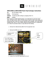
Mounting
Hole
IR Receiving
Eye
Power
Switch
RF Signal
Strength Meters
Carry Handle
XM Signal
Strength Meters
XM Modules
Installed
Module One Left and Right
Analog Audio Output
Tune Suite Front and Rear Panel Drawings
Optional Front Panel Controls
and Display Window
RF Modules
Installed
ADA Bus
Connector
AC Voltage
Selection Switch
Address and
Baud Rate
Selection Switch
AC
Inlet
AC Power Fuse

6
Audio Design Associates
www.ada-usa.com
Tune Suite Installation Manual
www.ada-usa.com 7
POWER
LED
12VDC
INPUT
OUTPUTOUTPUT
OUTPUTOUTPUT
INPUT
ACTIVE ANTENNA SPLITTER
AAS-4
POWER
LED
AM
ANTENNA
FM & WB
ANTENNA
QU
ADRITUNE
RF OUTPUT
ACTIVE ANTENNA COMBINER
AAC-1
1 2 3
To Tune Suite RF tuner modules
AAC-1 Antenna Combiner and AAS-4 Signal Splitter Connections
4
Locate AAC-1 where it is
protected from the weather
Locate and position antennas for optimum reception
For best results, RG-6 cable
to AML-1 should be exactly 6'
AML-1 AM
loop lntenna
(Provided)
For best results, ADA
recommends SE
Engineering SE 879
www.seengineer.com
Locate AAS-4 near Tune Suite
Use RG-6 cable terminated with
threaded F-Type connectors
for all connections
External 12 Vdc power
supply for line amplifier
THE AML-1 loop antenna is
directional-rotate for best reception

6
Audio Design Associates
www.ada-usa.com
Tune Suite Installation Manual
www.ada-usa.com 7
To XM Tuner Modules
75 Ohm RG-6 cable from
XMLA-1 to XMLS-4
Locate XM antenna and XMLA-1
in attic or indoor location for best reception
Locate XMLS-4 near Tune Suite
50 Ohm mini coax cables from
XMLS-4 to the Tune Suite
IMPORTANT NOTE: There must be at least
two modules connected from the XMLS-4 to the
Tune Suite for this configuration to work
50 Ohm mini coax
cable connected
to the XM antenna
XM antenna
positioned for best
reception
XMLA-1 Line Amplifier and XMLS-4 Line Splitter Connections
To XM Tuner Modules
Run 50 Ohm mini coax RG-174
or RG 316 terminated with
SMB connectors from
XMLA-1-50 to XMLS-4-50
(available from www.l-com.com)
Locate XM antenna and XMLA-1-50 in attic
or other indoor location for best reception
Locate XMLS-4-50 near Tune Suite
50 Ohm RG-174 or RG-316
cables terminated with SMB connectors
from XML-4-50 to the Tune Suite
IMPORTANT NOTE: There must be at least
two modules connected from the XMLS-4-50 to the
Tune Suite for this configuration to work
50 Ohm cable connected
to the XM antenna
XM antenna
positioned for best
reception
XMLA-1-50 Line Amplifier and XML-4-50 Line Splitter Connections

8
Audio Design Associates
www.ada-usa.com
Tune Suite Installation Manual
www.ada-usa.com 9
100 foot run of 50 Ohm mini coax
RG-174 or RG 316 cable terminated
with SMB connectors from
XMLA-1-50 to a single XM Module
(terminated cable available
from www.l-com.com)
Locate XM antenna and XMLA-1-50 in attic
or other indoor location for best reception
50 Ohm mini coax
cable connected
to the XM antenna
XM antenna
positioned for best
reception
XM Connection Option Using the XMLA-1-50 Line Amplifier to a Single XM Module
To XM Tuner Modules
Preterminated 50 Ohm
mini coax cable connected
to the XM antenna
Locate XMLS-4-50 near Tune Suite
50 Ohm RG-174 or RG-316
cables terminated with SMB connectors
from XMLS-4-50 to the Tune Suite
IMPORTANT NOTE: There must be at least
two modules connected from the XMLS-4-50 to the
Tune Suite for this configuration to work
XM antenna
positioned for best
reception indoors
XM Antenna and XML-4-50 Line Splitter Connections

8
Audio Design Associates
www.ada-usa.com
Tune Suite Installation Manual
www.ada-usa.com 9
Run 75 Ohm RG-6 cable
from XMLA-1 to XMC-75
Locate XM antenna and XMLA-1
in attic or indoor location for best reception
Locate XMLS-4 near Tune Suite
50 Ohm cable from
XMC-75 to single XM Module
Special cable connected
to the XM antenna
XM antenna
positioned for best
reception
XMLA-1 Line Amplifier and XMC-75 Impedance Converter Connections
Preterminated 50 Ohm cable from
XM antenna to single XM Module
XM antenna
positioned for best
reception
Direct Connection from XM Antenna to Single XM Module
L R
TUNER MODULE
4
ANT
INPUT
L R
TUNER MODULE
3
ANT
INPUT
This device complies with Part 15 of the FCC Rules. Operation is subject to the following two conditions:
1 This device may not cause harmful interference.
2 This device must accept any interference received, including interference that may cause undesired operation.

10
Audio Design Associates
www.ada-usa.com
Tune Suite Installation Manual
www.ada-usa.com 11
Making Connections to Your Tune Suite
Before making any connections, turn off the power to your preamplier and power amplier. Make
certain that all your connections are secure and that there is no tension on the cables that could cause
them to pull loose later.
Audio Connections
Connect a pair of high-quality interconnect cables from the Output jacks from each module of the
Tune Suite to any line level input jacks on your preamplier or multiroom controller. If the Tune Suite
is connected to an ADA Suite 16 or Suite 8 x 8 multiroom preamplier, take note of the inputs used
so the keypad’s labeling corresponds correctly.
Antenna Connection Options
There are multiple antenna connection options available for the Tune Suite. These options are dependent
upon how the Tune Suite is congured. The previuos pages illustrate the numerous antenna connections
using line ampliers and splitters in 75 ohm and 50 ohm congurations.
FM Antenna Connections
Adequate FM reception and subsequent sound quality is largely dependent upon your choice and
location of the antenna. There are several options to consider when selecting an antenna and connecting
it to the Tune Suite.
Outdoor FM Antenna
For best reception and maximum noise rejection, we recommend the use of a high-quality outdoor
FM antenna. Although this requires a little extra effort, the additional stations you can receive and the
superior sound quality will be worthwhile. For best results, ADA recommends the FM antenna model
Number SE 879 available from SE Engineering at www.seengineer.com.
Cable Transmission
Many cable companies transmit FM stations and cable TV audio signals along with the cable TV
channels. With some cable operators, the quality of the FM radio signal can be very good, depending
on the quality of their equipment. Check with your local cable company about the availability of FM
stations and possible additional charges for this service. Connection is the same as connecting a second
television: Connect a signal splitter to the incoming cable connection and use a 75 ohm F -type connector
to connect your television to one output of the splitter and the tuner to the other output.
Powered Antennas
A small powered indoor antenna is sometimes useful when it’s impractical to install an outdoor antenna
or where FM transmission is not available via cable or a community TV/FM antenna. However, powered
antennas sometimes add noise and distortion to the RF signal. In most cases, you can receive signals
better with the supplied dipole antenna.
AM Antenna Connections
An AML-1 loop antenna is supplied with the AAC-1 antenna combiner. This antenna provides excellent
reception in most cases. Once installed you will need to rotate the AML-1 For optimum reception.

10
Audio Design Associates
www.ada-usa.com
Tune Suite Installation Manual
www.ada-usa.com 11
XM Antenna
The XM antenna can be used either separately or in conjunction with the XMLA-1 Line Amplier
and XML-4 Line Splitter in 50 Ohm or 75 ohm congurations as illustrated previously. For optimum
reception and noise rejection, the XM antenna utilizes 50 Ohm mini-coax cable terminated with an
SMB type connector.
AC Line Cord
Once you have connected your audio cables and antennas, plug the female end of the IEC-65 standard
AC cord rmly into the rear mounted AC receptacle and make sure that it is properly seated, and then
connect the male end to the AC power source.
Activating XM Satellite Radio Service
If the Tune Suite is equipped with XM satellite radio modules, you may want to activate your module(s)
to receive all the channels XM radio can offer you, otherwise you will only receive free-to-air channels.
To activate your XM service, you will need to obtain the radio hardware ID numbers from each module
and have a valid credit card available.
Once you have obtained all your Radio Hardware ID numbers, you can activate the service by either
going to XM Radio’s website at www.xmradio.com or calling XM support at (800) 852-9696. After you
provide the necessary information to XM support, they will activate the module by sending activation
data to the specied XM modules. The XM modules must remain ON until the activation data is
received, otherwise it might be missed and you will need to contact XM once again.
To insure proper activation, ADA strongly advises that your radio must change channels at least once
after activation to retain activation; otherwise you will need to contact XM once again. This is very
important to retain your complete activation; otherwise you may have partial or no activation after a
power cycle. A partial activation is having some channels but not all. The same applies if a change to
your account is made, such as adding or removing premium channels.
Obtaining the XM Radio Hardware ID Number
If your unit is equipped with front panel controls, you can use the channel Up or Down controls to
access XM channel 0 where you will see the Radio Hardware ID. You can also enter setup mode to nd
your Radio Hardware ID. Repeat the setup procedures for all XM modules in the unit.
If your system is equipped with MC-5000, MC-5500, or MC-4500 keypad(s), you can also use the
numeric keypad to directly select channel 0 and Enter. This is where you will see the Radio Hardware
ID. You can also use the channel Up and Down commands to access XM channel 0 to view the Radio
Hardware ID number. You will need to repeat the XM activation procedure for all modules in the
unit.

12
Audio Design Associates
www.ada-usa.com
Tune Suite Installation Manual
www.ada-usa.com 13
Important Instructions when Creating a Third Party Control System for XM Modules
When programming a touchscreen or other third party control system to control XM, it is mandatory
to create commands for the operations below.
• There must be a way of accessing XM channel 0. This can be accessed either by direct access or
by using Channel Up or Down to access XM channel 0.
• There must be commands to select Channel Numbers Up and Down.
• There must be commands to select Categories Up and Down.
• Once within a category there should be a way to Select Stations Up and Down.
• Feedback of all the provided XM information must be displayed on the control interface.
It is important to note that Stations Up and Down are for a designated category and will not go through
all stations passing other Categories. The Tune Suite PCOS testing program and HEX commands
provided in this manual are essential in creating these commands. If you have any questions regarding
programming a control system to control XM modules, please contact Audio Design Associates.
Preset Number 1
XM Satellite Radio channel 0 is pre-programmed to occupy Preset 1 from the factory; the rest of the
29 of the 30 presets will be blank. This makes it easy to obtain the Radio ID number.
Special Diagnostics Parameters for XM Satellite Modules
There is a special diagnostic menu for XM modules that provides important information about XM
satellite transmission including the radio ID number for activation as well as signal strength and other
diagnostic tests. This information is obtained through the front panel setup menu, ADA keypads, or
the PCOS tester program.
Obtaining XM Diagnostic Information Using the Front Panel Controls
1. Enter the setup Menu by holding the down the Left Select
button.
2. Once in the setup menu, Radio ID number in the second row
in the display will alternate between Radio ID and its eight
character ID number.
3. Rotate the left Select knob until the cursor is ashing over
the R of Radio ID in the second row of the setup display.
4. Press the Center Tune knob to select the next XM Diagnostic
information category.
5. Continue pressing the center Tune knob to advance through all the XM diagnostic information.
XM diagnostic information is listed in the chart on the following page.
6. You can escape the diagnostic menu by selecting M > to return to the mani menu.
S L O T 1 S E T U P T Y P E = X M S A T
R A D I O I D S E T T Y P E
U N I T A D D R E S S = 0 I R = O F F
B L A N K I N G = O F F M >
S
E
L
E
C
T
M
O
D
E
T
U
N
E
S L O T 1 S E T U P T Y P E = T UN E R
RAD I O I D S E T T Y P
E
UN I T ADDRE SS = 0 I R = O F F
B L ANK I NG = O F F

12
Audio Design Associates
www.ada-usa.com
Tune Suite Installation Manual
www.ada-usa.com 13
Obtaining XM Diagnostic Information Using MC-5000, MC-4500, or MC-5500 Keypads
If your system is equipped with MC-5000, MC-5500, or MC-4500 keypad(s), you can use the numeric
keypad to access diagnostic information. Once there you will see your Radio, Signal Strength and other
Diagnostic Information for each module.
1. Enter the setup Menu by pressing 000 then Enter on the numeric section of the keypad.
2. Once in the setup menu, Radio ID number in the display will alternate between Radio ID and its
eight character ID number.
3. Press the ( * ) information button to select the next XM Diagnostic information category.
4. Continue pressing the ( * ) information button to advance through all the XM diagnostic information.
XM diagnostic information is listed in the diagnostic chart.
1
2
3
4
5
6
7
8
9
*
0
ENT
ABC DEF
JKLGHI MNO
TUVPQRS WXYZ
OFF
EXTRA
VO
ADJ
SEL
L
T
N
2
T
N
2
T
N
1
C
D
1
C
D
2
S
A
T
D
V
D
A
U
X
1
2
3
4
5
6
7 8 9
*
0
ENT
OFF
BA
SS
EXTRA
VOL
TREB
F
M
2
F
M
1
A
M
C
D
1
C
D
2
D
S
S
D
V
D
A
U
X
R A D I O I D
R A D I O I D
ADA MC-5500 and MC-5000 Keypads
XM Diagnostic Tests Label Front Panel and ADA Keypad Display Readout
RADIO ID Alternates between Radio ID label and 8 character ID number
RELEASE Static display of software release number
SIGNAL TEST Alternates between Signal Test label and signal strength
XM Diagnostic Test 1 QOS TEST Alternates between “QOS Test” Label and diagnostics
XM Diagnostic Test 2 TERR TEST Alternates between “Terr Test” Label and diagnostics
XM Diagnostic Test 3 SAT 1 TEST Alternates between “Sat 1 Test” Label and diagnostics
XM Diagnostic Test 4 SAT 2 TEST Alternates between “Sat 2 Test” Label and diagnostics
XM Diagnostic Test 5 TUNER TEST Alternates between “Tuner Test” Label and diagnostics
XM Diagnostic Test 6 SDEC STATUS 1 Alternates between “SDEC Status 1” Label and diagnostics
XM Diagnostic Test 7 SDEC STATUS 2 Alternates between “SDEC Status 2” Label and diagnostics
XM Diagnostic Test 8 SDEC STATUS 3 Alternates between “SDEC Status 3” Label and diagnostics
XM Diagnostic Test 9 SDEC STATUS 4 Alternates between “SDEC Status 4” Label and diagnostics

14
Audio Design Associates
www.ada-usa.com
Tune Suite Installation Manual
www.ada-usa.com 15
Obtaining XM Diagnostic Information Using the PCOS Tester Program
The Tune Suite PC control program helps you to congure and program the Tune Suite system for
operation with user interface control components such as ADA keypads and third party control systems.
You can also use the PCOS the program to access the XM diagnostic information.
To connect a computer to the Tune Suite, you will need the ISO-CAT to interface the computer with
the Tune Suite. The Tune Suite PC control program was developed to help congure and program the
Tune Suite system for operation with user interface control components such as ADA keypads and
third party control systems. The program also makes it easy to store preset stations into memory. You
can also save the each conguration on disc for later recall. The Tune Suite PC control program is
available for download at www.ada-usa.com
The Tune Suite control program has tabs along the top to open different sets of commands. The sections
in the Tune Suite control program include Conguration, Module Control, and Slot sections where you
can store stations into preset memory, label their call letters, and save the conguration on disc.
You can store up to thirty of your favorite XM stations into memory for each module installed in the
Tune Suite. The program has commands to select station channels and preset numbers. There are buttons
so you can scroll through station categories (category), and station names too. Additionally, the program
features diagnostic tools such as signal strength, serial number, and song information updating.
For RF modules, the program allows you to store thirty of your favorite FM, AM, or WX stations into
memory and even label their call letters. The program can navigate RF frequencies by direct access,
tune, seek or preset functions. The program also lets you select the frequency band, stereo or mono
operation, and stereo blending and de-emphasis.

14
Audio Design Associates
www.ada-usa.com
Tune Suite Installation Manual
www.ada-usa.com 15
Front Panel Operation of RF Modules
Storing and Labeling Preset Stations in the Tune Mode
Left Knob
Rotating the left Select knob: Moves the cursor to select between
modules.
Center Knob
Rotating the center Tune knob: Scrolls RF radio frequencies up
(clockwise) or down (counterclockwise). FM Frequencies tune in
200 kHz increments AM frequencies tune in 10 kHz increments
WX stations tune in 25 kHz increments between the 7 available
weather band stations. The far right of the display shows the band, or preset number or stored four
character label.
Right Knob
Pressing the right Mode knob: Opens up preset memory bank. Once open, rotate the right knob to scroll
to the desired preset number 1-30. If there is a channel already stored, an asterisk appears next to the
preset number. Pressing the right knob a second time allows you to label the station. Rotate the center
knob to move the cursor and Rotate the right knob to select the desired character. To delete the stored
preset station, press the center Tune knob when the preset memory bank is open. Pressing the right knob
again stores the selected frequency. Note: You can only store preset stations in the Tune or Seek mode.
Storing, and Labeling Preset Stations in the Seek Mode
Left Knob
Rotating the left Select knob: Moves the cursor to select between modules.
Center Knob
Rotating the center Tune knob: Rotating the tune knob clockwise will seek the next active radio
station, rotating the Tune knob counterclockwise will seek the previous active station.
Right Knob
Pressing the right Mode knob: Opens up preset memory bank. Once open, rotate the right knob to
scroll to the desired preset number 1-30. If there is a channel already stored, an asterisk appears next
to the preset number. Pressing the right knob a second time allows you to label the station. Rotate
the center knob to move the cursor and Rotate the right knob to select the desired character. To
delete the stored preset station, press the center Tune knob when the preset memory bank is open.
Pressing the right knob again stores the selected frequency. Note: You can only store preset stations
for RF modules in the Tune or Seek mode.
S
E
L
E
C
T
M
O
D
E
T
U
N
E
T U N E R 1 1 0 2 . 2 K D F C
T U N E R 1 0 6 . 5 K F O G
X M S A T
P R E S E T 1 4 4 4
X M S A T P R E S E T 2 0 9 6
2
T
U
N
E
3
4
T U N E R 1 1 0 4 . 5 F M T
T U N E R 1 1 0 4 . 5 P R 2 0 U
T U N E R 1 S T O R E ? * P R 2 0 N
T U N E R 1 L A B E L ? K F O G E

16
Audio Design Associates
www.ada-usa.com
Tune Suite Installation Manual
www.ada-usa.com 17
T U N E R 1 1 0 4 . 5 F M P
T U N E R 1 1 0 4 . 5 P R 2 0 S
T U N E R 1 S T O R E ? * P R 2 0 E
T U N E R 1 L A B E L ? K F O G T
T U N E R 1 9 9 . 3 F M B
T U N E R 1 1 0 2 . 1 P R 2 0 A
T U N E R 1 1 0 4 . 5 K F O G N
T U N E R 1 1 0 5 . 3 K I T S D
Front Panel Control in the Preset Mode
Left Knob
Rotating the left Select knob: Moves the cursor to select between
modules. Rotating the center Tune knob: Scrolls preset stations
up (clockwise) or down (counterclockwise). Only stations
programmed into memory will appear when selecting preset radio
stations with the center Tune knob. Preset numbers not stored in
memory are bypassed.
Right Knob
Rotating the right Tune knob: Scrolls between Tune, Seek, Preset, Band, and Stereo/Mono modes.
S
E
L
E
C
T
M
O
D
E
T
U
N
E
T U N E R 1 1 0 2 . 2 K D F C
T U N E R 1 0 6 . 5 K F O G
X M S A T
P R E S E T 1 4 4 4
X M S A T P R E S E T 2 0 9 6
2
P
S
E
T
3
4
Front Panel Control in the Band Mode
Left Knob
Rotating the left Select knob: Moves the cursor to select between modules.
Center Knob
Rotating the center Tune knob: Scrolls through FM, AM and WX frequency bands. When scrolling
between bands the last tuned frequency for each band is selected.
Right Knob
Rotating the right Tune knob: Scrolls between Tune, Seek, Preset, Band, and Stereo/Mono

16
Audio Design Associates
www.ada-usa.com
Tune Suite Installation Manual
www.ada-usa.com 17
Front Panel Operation of XM Modules
Front Panel Control in the Channel Mode
Left Knob
Rotating the left Select knob: Moves the cursor to select
between modules.
Center Knob
Rotating the center Tune knob: Scrolls XM channel numbers
up (clockwise) or down (counterclockwise). Once scrolling
stops, the displayed channel is selected. If channel is stored
as a preset, the preset number also appears. Pressing the center knob will delete the channel from the
selected preset number. Pressing the center Tune knob: Scrolls station information: station/category/
station name/artist/song.
Right Knob
Rotating the right Mode knob: Scrolls between tuning modes (channel number, genre, preset number,
and station). Pressing the right Tune knob: Opens up preset memory bank. Once open, rotate the
right knob to scroll to the desired preset number 1-30. If there is a channel already stored, an asterisk
appears next to the preset number. Pressing the right knob again stores the selected channel. To delete
the stored preset station, press the center Tune knob when the preset memory bank is open. Note: You
can only store preset stations in the CH or CAT mode.
T U N E R 1 S T E R E O M O D E S
T U N E R 1 M O N O M O D E T
T U N E R 1 \
T U N E R 1 M
X M S A T 1 X M 7 6 P R 1 0 C
X M S A T 1 X M 1 1 5 P R 1 5 H
X M S A T 1 S T O R E ? P R 2 9
X M S A T 1 S T O R E D * P R 2 9
S
E
L
E
C
T
M
O
D
E
T
U
N
E
T U N E R 1 1 0 2 . 2 K D F C
T U N E R 1 0 6 . 5 K F O G
X M S A T
P R E S E T 1 4 4 4
X M S A T P R E S E T 2 0 9 6
2
C
H
3
4
Front Panel Control to Change Stereo/Mono Settings
Left Knob
Rotating the left Select knob: Moves the cursor to select between modules.
Center Knob
Rotating the center mode knob: Selects stereo or mono for the selected station. Since AM and WX
stations don’t broadcast in stereo, this setting only applies for FM stations.

18
Audio Design Associates
www.ada-usa.com
Tune Suite Installation Manual
www.ada-usa.com 19
Front Panel Control in the Category Mode
Left Knob
Rotating the left Select knob: Moves the cursor to select between
modules.
Center Knob
Rotating the center Tune knob: Scrolls categories up (clockwise)
or down (counterclockwise). When you stop rotating the knob,
the rst station within the category is selected. Pressing the center
Tune knob: Causes the CAT label to ash in the display. While ashing, rotate the center knob to
select the desired station within the current category. If no station is selected within fteen seconds,
the display will returnto the last selected station.
Right Knob
Rotating the right Mode knob: Scrolls between tuning modes (channel number, genre, preset number,
and station). Pressing the right Tune knob: Opens up preset memory bank. Once open, rotate the
right knob to scroll to the desired preset number 1-30. If there is a channel already stored, an asterisk
appears next to the preset number. Pressing the right knob again stores the selected channel. To delete
the stored preset station, press the center Tune knob when the preset memory bank is open. Note: You
can only store preset stations in the CH or CAT mode.
S
E
L
E
C
T
M
O
D
E
T
U
N
E
T U N E R 1 1 0 2 . 2 K D F C
T U N E R 1 0 6 . 5 K F O G
X M S A T
P R E S E T 1 4 4 4
X M S A T P R E S E T 2 0 9 6
2
C
H
3
4
X M S A T 1 P R E S E T 1 0 4 4 P
X M S A T 1 X M 4 0 P R 1 4 S
X M S A T 1 R O C K E
X M S A T 1 L E T I T B E T
X M S A T 1 R o c k C
X M S A T 1 H I t s A
X M S A T 1 S T O R E ? P R 8 T
X M S A T 1 S T O R E D * P R 8
Front Panel Control in the Preset Mode
Left Knob
Rotating the left Select knob: Moves the cursor to select
between modules.
Center Knob
Rotating the center Tune knob: Scrolls channel and preset
numbers up (clockwise) or down (counterclockwise).
Right Knob
Rotating the right Tune knob: Toggles between signal strength and XM channel number.
S
E
L
E
C
T
M
O
D
E
T
U
N
E
T U N E R 1 1 0 2 . 2 K D F C
T U N E R 1 0 6 . 5 K F O G
X M S A T
P R E S E T 1 4 4 4
X M S A T P R E S E T 2 0 9 6
2
P
S
E
T
3
4

18
Audio Design Associates
www.ada-usa.com
Tune Suite Installation Manual
www.ada-usa.com 19
S L O T 1 S E T U P T Y P E = T U N E R
A M L E V E L = 2 S E T T Y P E
U N I T A D D R E S S = 0 I R = O F F
B L A N K I N G = O F F M >
Setting Conguration Parameters with the Front Panel Controls
There are several operational parameters that can be changed using the front panel controls. Adjustable
parameters include setting the unit to blank out the display, activate the IR receiver, and set the Unit
Address to match the setting on the rear panel. For RF modules, you can set the muting levels for AM,
FM, and WX, turn on Stereo ltering, and set the de-emphasis levels. For XM Modules, you can obtain
several levels of diagnostic information including the radio ID number, and signal strength and other
diagnostic information regarding XM satellite transmission. This diagnostic information is described
earlier in this manual.
Entering the Setup Menu
Hold down the left Select knob for ve seconds to activate the setup menu. Generally, while in the
setup menu, you can change between parameters by rotating the left Select knob. Once the parameter
is selected, you can change the setting by rotating the center Tune knob.
Using Front Panel Controls to View Slot Settings
Left Knob
Rotating the left Select knob: Moves the cursor to select setup
parameters. Note: You can exit the setup menu by selecting M
> and Pressing the Left Select knob.
Center Knob
Rotating the center Tune knob: Scrolls between all four slot positions to view the current parameters
of each module. The cursor must be on the top line while choosing slot positions.
S
E
L
E
C
T
M
O
D
E
T
U
N
E
S L O T 1 S E T U P T Y P E = T U N E R
A M L E V E L = 2 S E T T Y P E
U N I T A D D R E S S = 0 I R = O F F
B L A N K I N G = O F F M
>
Using Front Panel Controls to Set AM Muting Level-RF Module Specic
Left Knob
Rotate the left Select knob: To position the cursor on the second row.
Center Knob
Rotate the center Tune knob: To scroll through setup parameters: (AM level, FM level, WX level,
Filtering, and de-emphasis, and software revision number.) Leave cursor at rst parameter: AM
level.
Right Knob
Rotate the right Mode knob: To change the AM level muting level for the selected module from 0 to
10. Lower settings allow selection of weaker stations during scanning.

20
Audio Design Associates
www.ada-usa.com
Tune Suite Installation Manual
www.ada-usa.com 21
Using Front Panel Controls to Set FM Muting Level-RF Module Specic
Left Knob
Rotate the left Select knob: To position the cursor on the second row.
Center Knob
Rotate the center Tune knob: To scroll to the FM Level setup parameter.
Right Knob
Rotate the right Mode knob: To change the FM level muting level for the selected module from 0 to
10. Lower settings allow selection of weaker stations during scanning.
Using Front Panel Controls to Set WX Muting Level-RF Module Specic
Left Knob
Rotate the left Select knob: To position the cursor on the second row.
Center Knob
Rotate the center Tune knob: To scroll to the WX Level setup parameter.
Right Knob
Rotate the right Mode knob: To change the WX level muting level for the selected module from 0
to 10. Lower settings allow selection of weaker stations during scanning.
Using Front Panel Controls to Set De-emphasis Level-RF Module Specic
Left Knob
Rotate the left Select knob: To position the cursor on the second row.
Center Knob
Rotate the center Tune knob: To change the setup level parameter to de-emphasis.
Right Knob
Rotate the right Mode knob: To change the de-emphasis level to 50 uS or 75 uS.
Using Front Panel Controls to Set the Noise Filter Level-RF Module Specic
Left Knob
Rotate the left Select knob: To position the cursor on the second row.
Center Knob
Rotate the center Tune knob: To change the setup level parameter to Filter.
Right Knob
Rotate the right Mode knob: To change the lter to Auto or Off. With the lter in the Auto position,
noise associated with weaker stations will be ltered out.
/