Page is loading ...

MFJ-416 Instruction Manual
IMPORTANT NOTICE
Some versions of the MFJ-9406 require a minor change on the main pc board before installation of the
MFJ-416 CW adapter. To determine if this change must be made to your transceiver, locate R54--
about 1" to the right of HDR1 (HDR1 is the header where the CW adapter plugs in).
[ ] If no part is installed at R54 on your MFJ-9406 pc board, than you must make the modification
outlined in this sheet.
[ ] If a 4.7 uH molded choke is installed at R54 on your MFJ 9406 (yellow, violet, gold, silver), then
disregard this notice and proceed with CW adapter installation.
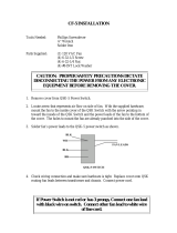
Modification:
To modify your MFJ 9406, find the 4.7uH molded choke included with the CW adapter kit (yellow,
violet, gold, silver). Install this choke, following the diagram below. The choke is needed to
complete the key-line connection between your CW adapter and the MFJ-9406 balanced
modulator. Without it, your transmitter will not generate RF power when the key is
depressed.
Be sure to keep choke leads as short as possible, and position the body of the choke close to HDR2.
This completes the modification, and you may now proceed with normal installation of the
CW adapter.
Note: Do Not attempt to install the 4.7 uH RFC at R54 on your circuit board.
MFJ ENTERPRISES, INC.
300 Industrial Park Road
Starkville, MS
39759
USA
Tel: 601-323-5869 Fax: 601-323-6551
Version OA
COPYRIGHT ® 1996 MFJ ENTERPRISES, INC.

4
MFJ-416 Instruction Manual
MFJ-416 CW Adapter
Introduction: The MFJ-416 adapter lets you communicate on CW using the MFJ 9406. No mode
selection is needed-simply tune in and start sending. Semi-QSK switching activates the transmitter and
inserts the correct frequency-offset (offset may be adjusted to preference by resetting an internal
trimpot). The MFJ-416 works with manual or semiautomatic keys, and with most electronic keyers. A
built-in sidetone generator provides audible feedback. The CW note generated by the MFJ-9406 is Al
carrier, not an audioderived tone. Control gates are timed to ensure strong first-character attack,
chirp-free offset switching, and comfortable QSK-hold time. FET control gates prevent adapter
interaction with the MFJ-9406's normal SSB operation.
Installation: The diagram below illustrates how to install your adapter. Simply slip the adapter board
socket onto the 4-pin header at the rear of the transceiver's main pc board, as shown. Secure in place with a
#6 screw, using the mounting stud located at the rightrear corner of the main board. Tack-solder the
attached wire lead to the right-hand pin of the radio's
Fine Tuning
control
Sidetone: If you wish to use the sidetone generator built
into
your electronic keyer, remove the shorting
pin from HDR1 on the adapter board. This will disable the sounder.

4
MFJ-416
Theory of Operation: Please refer to the schematic shown below:
Key Switch: A ground-path through the key jack activates DC switch Q1, providing logic-high
output. This, in turn, activates PTT switch Q3, balanced-modulator keying switch Q2, VFO
frequency-offset switch Q4, and sidetone generator P1.
Semi-QSK Switch Q3: When Q3 conducts, it provides a ground path that activates the transceiver's
relay driver. RC circuit R4/C 1 delays PTT drop, providing approximately 1/2-second semi-QSK hold-
time between CW characters. Blocking diode D2 isolates the LC hold circuit from other gates on the Q 1
control line.
CW Keying Switch Q2: When FET-switch Q2 conducts, it unbalances the transmitter's modulator
(U5), forcing carrier generation.
Transmit Offset Switch Q4: When Q4 conducts, it passes a DC bias to the radio's Fine Tune
control. This overrides the control's normal bias, forcing the VFO to oscillate approximately 600-Hz
higher in frequency (offset bias can be adjusted by R6 to suit operator preference). R5/C2 provides a
short hold-delay to the gate of Q4 to ensure that offset bias persists beyond CW-character completion.
Blocking diode D3 isolates Q4 from receive-mode bias, and C4 bypasses 50-MHz RF pickup on the
control line.
Sidetone Generator P1: When Q1 goes high, piezoelectric sounder P1 activates to emit a 2.4-kHz
sidetone note. Current-limiting resistor R7 sets volume level, and C3 bypasses AF hash
generated during oscillation.
General: Once installed, the MFJ-416 is powered at all times. Under normal operating
conditions, you can expect your MFJ-9406 to deliver 5-8 Watts CW output into a 50Ohm load. The
adapter has been tested for RF immunity, and may be used with the MFJ9406 to drive
six
meter
linear amplifiers such as the Mirage A1015-G.
Instruction Manual

4
MFJ-416 Instruction Manual
Operating Cross-Mode CW: While the MFJ-9406 is fixed in the USB mode, many
imported multi-mode transceivers automatically switch from USB for voice to LSB for CW operation.
This mode difference does not disrupt your ability to work those stations. However, CW signals
received on LSB radios will appear inverted from how they are received on the MFJ-9406. Thus, if
you tune a station for a low CW tone (below the normal 600 Hz offset), you'll sound correspondingly
high (above the 600-Hz offset) to that station. Likewise, up-frequency QRM on your radio will
sound down-frequency on LSB-mode radios. The diagram below may help you visualize how
this works:
No special operating adjustments are necessary to operate "cross-mode", beyond an awareness that LSB-
mode stations have an upside-down view of the spectrum you share.
In Case of Trouble:
[
I
Replying CW stations are consistently off frequency: Reset offset control (R6).
Remember, most 50-MHz stations operate CW on LSB, so increase offset to lower average pitch
(clockwise), and decrease it for higher-pitch (counter-clockwise).
[ ] Continuous carrier heard between CW characters: Poor carrier null. To rebalance
modulator (U5), turn mic-gain fully down, key your mic's PTT switch, and adjust Carrier Balance
R57 for minimum signal using a second receiver or spectrum analyzer as a monitor. Carrier should be
at least 40-dB down from full RF output.
[
I
Ambient audio on CW note: Your microphone should cut the audio line--as well as the PTT
line--when the PTT button is released. If your microphone does not do this, unplug it when operating
CW.
[
I
QSK-hold too slow: Reduce value of R5 (try 2.2M) or C1 (try .05 uF).
If you have any problem with this unit first check the appropriate section of this manual. If the
manual does not reference your problem or your problem is not solved by following the
manual, you may
call
MFJ Technical Service at 601-323-0549 or the MFJ Factory at 601323-
5869. You will be best served if you have your unit, manual and all information on your station
handy so you can answer any questions the technicians may ask.
/