1
© Copyright 2005 Printed
Before You Start
Your Land Pride Electric Actuator is exclusively
designed for your Land Pride FPS48 Food Plot Seeder.
Please read these installation instructions and the Food
Plot Seeder Operator’s Manual thoroughly before
beginning. Especially read information relating to safety
concerns. Also included in the Operator’s Manual is
important information on operation, adjustment,
troubleshooting, and maintenance for this attachment
(some manual sections do not apply to all accessories).
A separate Parts Manual for replacement parts can be
purchasedfromyourdealeroravailablefreeofchargeat
www.landpride.com. Have model and serial numbers
handy when placing an order.
Manual Part Numbers:
• Operator’s Manual. . . . . . . . . . . . . . . . . 322-118M
• Parts Manual . . . . . . . . . . . . . . . . . . . . . 322-118P
General Information
These assembly instructions apply to the following
Electric Actuator Accessories listed below:
322-119A ELECTRIC LIFT ACTUATOR PACKAGE
Tools required:
•
Safety Glasses
• Work Gloves
Assembly Instructions
Adetailedlisting of parts for the accessory kit is provided
on page 3. Use the list as a checklist to inventory parts
received.Pleasecontact your local Land Pride dealer for
any missing hardware.
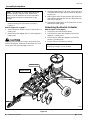
Linear Actuator Installation
Refer to Figure 1-1:
1. Park the Food Plot Seeder on a flat level surface.
When you see this symbol, the subsequent
instructions and warnings are serious - follow
without exception. Your life and the lives of
others depend on it!
!
IMPORTANT: Before you begin, read these
instructions and check to be sure all parts and tools
are accounted for. Please retain these installation
instructions for future reference and parts ordering
information.
2. Adjust ratchet jack to lower the FPS48 disc gangs
onto the ground until all pressure is removed from
theclevispins.Removeratchetjackfromtheseeder.
3. Attach lower end of linear actuator (#3) to the front
mounting lug (B) with hitch pin (#2). Secure in place
with hair pin clip (#1).
4. Attach hand controller (#4) to the linear actuator by
plugging connector (E) into connector (F).
Linear Actuator Assembly ()
Figure 1-1
Refer to Figure 1-2 on page 2:
!
CAUTION
Make sure all electrical wiring is supported insuch a way that
it will not come in contact with trash, lift mechanism, rotating
discs, pinch points, vehicle rotating components, hot exhaust
components, etc.
23907
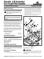
For Model FPS48 Plot Ranger
Electric Lift Actuator
For Food Plot Seeder
4/17/06
Manual No. 322-121M

2
Manual No. 322-121M 4/17/06
Land Pride
Assembly Instructions
■
5. Wrap electrical wiring around one of the tie down
straps and along the hitch frame as shown in
Figure 1-2.
Refer to Figure 1-1 on page 1:
6. Attach white wire alligator clip (D) to the positive (+)
battery post.
7. Attach black wire alligator clip (C) to the negative (-)
battery post.
!
CAUTION
Extending and retracting the actuator creates pinch point
hazards. Keep fingers, hands and all extremities clear of all
moving parts when operating toggle switch (G).
NOTE: Ties (#5) may be used to help secure the
electrical wiring. If they are used, attach them
loosely or out of material that can be removed to
allow removal of electrical components for dry
storage.
8. Operate toggle switch (G) to move upper clevis end
of actuator until it aligns with the rear axle adjusting
lug hole (A).
9. Attach upper end of Linear Actuator (#3) to the rear
axle adjusting lug hole with hitch pin (#2) and secure
with hair pin clip (#1).
10. Operate the toggle switch at the control box to raise
and lower the disc gangs.
Unhooking the Electric Actuator
Refer to Figure 1-1 on page 1:
1. Unplug the connector at the actuator.
2. Disconnect the black wire alligator clip from the
negative (-) battery post.
3. Disconnect the white wire alligator clip from the
positive (+) battery post.
4. Unhitch Electric Actuator from vehicle.
IMPORTANT: Protect actuator controller from
moisture by storing it in a dry location.
Electric Actuator Assembly
Figure 1-2
23916
Tie Down Straps
5
Wrap Electrical
Wiring As shown

4/17/06
Manual No. 322-121M
3
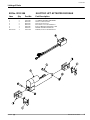
Item Qty. Part No. Part Description
Land Pride
Listing of Parts
■
1 2 322-109H CYLINDER ADAPTER WELDMENT
2 2 802-130C HHCS 1/2-13X2 1/2 GR5
3 2 803-019C NUT LOCK 1/2-13 PLT
4 2 805-012C PIN CLEVIS 1 X 2 1/8 USABLE LG
5 1 833-318C ELECT. LINEAR ACTUATOR 8" STRK
6 1 833-402C WIRING HARNESS W/SWITCH
Not Shown 1 322-121M MANUAL, ELECT. LIFT INSTRUCT.
Kit No. 322-119A ELECTRIC LIFT ACTUATOR PACKAGE

Corporate Office: P.O. Box 5060
Salina, Kansas 67402-5060 USA
www.landpride.com
-
 1
1
-
 2
2
-
 3
3
-
 4
4