Page is loading ...

Installation Instructions
Laundry
Center
Washer
l
Dryer
240 Volt

Check code requirements,
some codes do not permit
or llmlt mstallatlon of clothes
dryers ln garages, Closets.
mobile homes and sleeping
quarters. Contact your local
bulldIng Inspector.
Hot and cold water faucets:
must be wlthin 4 feet of the
back of the washer/dryer and
Protection from weather:
do not store or operate
washer/dryer below 32°F
(some water may remam In
washer). Proper operatlon
of dryer cycles require
temoeratures above 45°F.
see’ Use and Care Guide for
“Wmterlzmg” Information.
Before you
Check locatlon where
washer/dryer WIII be mstalled
Proper mstallatlon Is your
responsibility. Make sure you
have everything necessary
lor correct installallon
Grounded electrical outlet:
IS required. See Electncat
Requirements.
Standpipe drain system:
needs a two-inch diameter
standplpe with minimum
provide water
pressure 5-100
PSI.
Water heater: set to deliver
140°F water to the washer.
I”” “IWIII O,‘..mS.’
needs a 20-gallon laundry
lub. Top of lub must be at least
26 inches high and no higher
46 inches from floor.
Exhaust
Requirements,
: If a lonoer drain hose is
\ //&ded’,,drain hose, Part No.
366423 and hose exlenslon
kit Part No. 265442 are
.-’ - ~~
available from KitchenAid
authorized parts
dlslributors.
IMPORTANT: OBSERVE
ALL GOVERNING CODES
AND ORDINANCES.
Part No. C-ZAT\W
265320,
K I\\ \ I
-.-. -- .
from KitchenAId \ m
U/
location
must be lame
aulhorlzed
pads
distributors
-__- .._. -. ~~
enough to fully open dryer
door. See Backcover for
recessed area requirements
and product dimensions.
SEE
ler/drver 1 inch
---
RECESSED AREA
+\
- _ _
under wasp
INSTRUCTIONS ON
BACK COVER.
Support: floor must be sturdy
enough to support washer/
CAUTION:
. It is the customer’s personal
responsibility to ensure that
gasoline, paint, thinners and
other flammable material are
not used or stored near the
washer/dryer. Fumes from
these materials could result
in fire or explosion.
l
Never Install washer/dryer
up against draperies or
curtains. Keep any and ail
items from falling or collecting
behind the washer/dryer.
9 Replace all access panels
before operating
washer/dryer.
FOR YOUR SAFEPY:
l
Do not exhaust dryer into a
chimney, furnace cold alr
duct, attic or crawl space, or
any other duct used for
venting. Accumulated lint
could become a fire hazard
or moisture could cause
damage.
l
The exhaust system should
be cleaned at least every 2
years.
l
Flexible duct should never
be installed concealed in
walls. ceiiina or floor.
dryer-weight of 375 pounds.
7bol.s needed for I
See Panel F. Alternate Electrical
Connection, for detailed instructions.
4. When removing Ihe power supply
cord (piglail), the appliance may be
connected directly to the fused
disconnecl (or circuit breaker) box
through flexible armored or non-
metallic sheathed 10 gauge copper
cable. It IS the personal
responsibility and obligation of the
customer to contact a qualified
installer lo assure that the electrical
installation is adequate and is in
conformance with the National
Electrical Code ANSI/NFPA 70-1967
and local codes and ordinances.
Allow slack in Ihe line between the
wall and the appliance so that it can
be moved if servicing is ever
necessary. A U.L. recognized strain
relief must be provided at each end
of the power supply cable (at the
appliance and at Ihe junction box).
Wire sizes (10 gauge COPPER
WIRE ONLY) and connection must
conform with the ratino of the
appliance (30 amperes): DO NOT
USE AN EXTENSION CORD.
I
Electrical 6
vequhments
Electrical ground is required on
this appliance.
Warning: Improper connection 01
the equipment grounding
conductor can result in a risk of
electrical shock.
1. A three-wire smgle phase
120/240 volt 60Hz AC only electrica
supply (or three-wire 120/206 volt if
specified on nameplate) is required
on a separate 30 ampere circuit,
fused on both sides of the line (time
delay fuse or clrcult breaker is
recommended). Do not have a fuse
in the neutral or ground circuit.
2. This washer/dryer IS equipped
with a 30 amp rated flexible type
power supply cord (plglail). Where
local codes permit, It must be -
plugged into a mating
30 amp receptacle (l&mR)
(NEMA type lo-30R). 3-wire
See Figure 1.
3. IF THE
&
receptacle I
POWER SUPPLY CORD Figure’
IS REMOVED, THE WASHER/
DRYER MUST BE CONNECTED
WITH 10 GAUGE COPPER WIRE
ONLY. Aluminum wire must not be
used at the washer/dryer appliance
terminal block, to avotd potentially
unsatisfactory connections.
5. CAUTION - For moblle home
lnstallatlon the 3-wire power supply
cord must be removed and the
appliance wiring must be revised.
The appliance frame must not be
connected to the neutral terminal,
but must be connected to Ihe
grounding wire(green) of power
supply cord. See Panel G, Alternate
Electrical Connection - Mobile
Home Installation, for detailed
supply cord (pigtail) must be used.
This cord contains four No. 10 gauge
copper conductors with spade or
ring terminals on the washer/dryer
end and terminating in a NEMA type
14.30P plug on supply end. The
Fourth (grounding) conductor must
be identified by a green cover and
the neutral conductor by a white
cover. Cord should be type SRD or
SRDT. with a U.L. recognized strain
relief, and be at least 3 feet and no
more than 6 feet long. The four wire
power supply cord and strain relief
are not provided with the
washer/drvec
instructions.
Figure 2
If a four-wire receptacle of
NEMA type 14.30R (see Figure 2)
IS available, a matching power
4NEL A

Exhaust
requirements 1
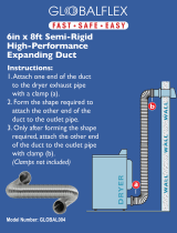
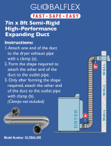
Four Inch Metal Exhaust Duct IS
.equlred. (Do nol use 3
in
exhaust duct.) Metal
flex~
nay be used. Non-meta
duct IS not recommende
Use Duct Tape to
peal all joints.
Exhausting the dryer
outside is recommende
II dryer cannot be exhaus
sutside, use Exhaust Defl
Kit
LCK4500 available from your
KitchenAId dealer.
Exhausting the dryer through the
side of the washer/dryer requires
use of Side Exhaust Kit LCK4600.
Follow installation mstructions with
the kit for proper exhaust
mslallation.
Mobile Home Exhaust
Reouirements: see Panel F
Al&ate Exhaust Method.
Metal Flexible Duct must be fully
extended and supported when the
dryer IS III its final posItIon. DO
NOT KINK OR CRUSH THE DUCT
Exhaust Duct should end with an
exhaust hood to prevent exhausted
air returning Into dryer. The outlet 01
the hood musl be at least 12 Inches
from Ihe ground or any object lhat
may be in path of exhausl.
2%” inch outlet Exhaust Hood
should be used with short systems
only. This outlet creates greater
backward pressure than other hood
types.
Exhaust Hoods with magnetic
latches should not be used
Maximum Length of the exhaust
system depends upon the type of
duct used, number of elbows
and type of exhaust hood. The
maximum lenglh for both ngid and
flexible duct is shown in charf
Caution: Exhaust Systems longer
than speclfled WIII -
l
Shorten the life of the dryer.
l
Reduce performance-cause
longer drying times and Increase
energy usage.
l
Accumulate Ilnt.
Now start...
1.
Use a ‘/IS Inch socket wrench to
remove two bolts holdina Ihe wood
pallet to the bottom of th>
washer/dryer.
PANEL B
2
n
Remove pallet. Remove
parts from plastic package.
Check thal all parts were included.
l
1 h&e clamp
l 4 flat water hose washers
l
1 elastic straw
l
1 ire term ’
Insert rear levelmg leg into
the hole in’the rear corner.
Push the leg in until it snap
inlo place. Do the same
thmg with the other
leveling leg in the
other rear corner.
~ lea.checkto I
rw
Pushuponone 1
Check Ihe other leg in the same
way. (If the legs don’t adjust, go
through step 3 again.)
I
:ind the diamond marking in the
idges of the front legs. Start to
icrew the front legs into the hole in
he triangular brace at the front
:orner of the machine. A little liquid
detergent to lubricale the screw
VIII help. Use pliers to turn lhe leg all
he way to the diamond marking.
he washer/dryer,
~uired.
people are
damaging the
producl do not
remove corner post before cutting.
Remove carton.

Remove the 2 rear corner pieces
attached to the back of washer/
dryer: Do not remove the foam
shipping pieces between the
washer and dryer until unit is in
place.
Shlpplng Strap
with key.
NOTE: Use one hand to hold
down agltator when removing
shipplng straps. After straps
ara removed release agitator, it
will move upward.
Move foam shipping pieces
outward iust enouah to clear the
washer lb. Open iasher lid. Latch
under Ihe dryer will hold lid open.
Pull three straps with
completely out of wa
Numbers correspond
to steps
PANEL C
10.
Read label. Firmly jerk then pull
one of the three shipping straps up
until strap with key is.co?nplelely
removed horn washer. Repeat for
other two shipping straps.‘Put
straps in the same area as rear
corner shipping pieces.
r
11.
Remove label.
Take hoses out of basket.
1 Place hoses with other parts.
Release washer lid by pushing up
on latch. Close lid.
: Do ns
:piea
dtyel
move foam shipping
1-n the washer and
il unit is in place.

Use new hoses and washers
that came with your KitchenAid
washer/dryer.
dlsconnecL Remove
13
coupling
washer
m
clamp and coupling. Estimate length
of dram hose needed. Cut flexible
end of hose. (Do not cut hook-
shaped end of drain hose.) Push
and twlsl couplmg securely onto
drain hose. (You should tee1 lop Of
hose through coupling.) Slide clamp
over couplmg and hose. Remstall
drain hose. See slep 15.
Insert a flat washer Into each
end of the lnlel hoses. Check lhal
I
washers are firmly sealed in
couplings.
connector. Use pliers lo open
\
clamp and slide clamp over drain
hose. Check for good fll.
I
16
n
wire Iorm and
wrap around free end
of drain hose lo make
a “hook” shape.
Before atlachmg water Inlet hoses,
run waler through both laucets
IO
get rid of particles in waler lines Ihat
might clog hoses.
Met valves are plastic, d
strip or crossthread.
20.
Atiach botiom hose (inlet marked
“H”) lo hot waler taucel. Attach top
hose (inlet marked “C”) lo cold wale1
faucet. Tighten couplings lo faucet
by hand, then use pliers to make
fmal two-thirds turn.
17
Move washer/dryer close
lo final position. Put “hook”
a end of drain hose into
Attach hose to bottom inlet valve
opening first. Then second hose
IO
lop inlet valve. Tighlen couplings
by hand, then use pliers to make an
addillonal Iwo-thirds turn.
laundry tub or standpipe.
Check for proper length of
drain hose.
Remove and discard plug.’
Numbers correspond
to steps
Install wire form on drain
hose.
PANEL D

love washerldryer to its
ermanent location.
Check levelness of
n washer/dryer by
Ilacing a carpenter’s level on top of
dasher, first side to side then front
I back. If it is not level, screw the
‘ant legs up or down to adjust. Tilt
rasher forward raising back legs 1”
IH of floor to adjust rear self-
:veling legs. Gently lower washer
3 floor. Make final check with level.
22
n
‘ut “hook” end of drain hose in tub
jr standpipe. Secure drain hose by
vrapping the plastic strap around
he hose as shown in Figures A-C.
f drain hose cannot be strapped in
,lace, it must be cut exactly to length
io the “hook” end is held tightly over
he edge of the tub or standpipe as
ihown m Figure D.
:HECK THAT HOSE IS NOT
MISTED OR KINKED AND IS
jECURELY IN PLACE.
?xhausf ductwork can not be
:onnected from the side of the
vasher/dryer, the exhaust duct can
)e reached from the front, through
he access panel. Remove the
access panel by unscrewing 2
)hllllps heads screws located at
he top of the panel. Set panel and
icrews aside
NEL E
24.
To exhaust the dryer straight from
lack of the washer/dryer unit,
jetermine if any additional exhaust
duct is needed (see Exhaust
qequirements. Panel 6). To exhaust
.he dryer to either side or Inside
:heck If additional exhaust duct is
Teeded and see Alternate Exhaust
Wethods. Panel F Connect exhausl
jucl to exhaust hood.
Use duct tape to seal all joints.
26.
CHECK ELECTRICAL
REQUIREMENTS. BE SURE YOU
HAVE CORRECT ELECTRICAL
SUPPLY AND RECOMMENDED
GROUNDING METHOD. Check the
installation inslructlons to see that
you have completed each step.
Complete any missed steps before
you continue.
Check that all parts are now
installed. See parts list, Panel A.
If there is an extra part, go back
through steps to see which step
Check that you removed all the
shipping pieces including the three
shipping straps with keys.
If you do not remove the shipping
straps, your washer/dryer may
-
“walk” awav from its tocatlon.
DhilliDs screwdriver
Check that you have all of your tools
30.
Turn on waler faucets and check
for leaks. Tighten couplmgs if there
is leaking.
31.
Plug electrical cord into grounded
outlet.
32.
If access panel was removed to
install ductwork, replace access
panel. Be sure to tighten both
screws.
33
1
Take a few minules and read the
Use and Care Guide to fully
understand your new wastierldryer.
Now start the washer and allow
it to complete the regular cycle.
Remove the tape across the dryer
lint screen. Check to be
sure lint screen is in its proper
position. Wipe out drum. Start dryer
and allow it to complete a cycle to
make sure the dryer is working
properly
35.
Finally, save all literature and keep
with the washer/dryer. Save all
shlpping materials for reshipping.
You have
successfully Installed your
KItchenAid washer/dryer.
To gel the most efliclent use from
your new washer/dryer read your
KItchenAId Use and Care Guide.
Congratulations!
Keep lnete~ation instructions nearb)
where you can refer to them.
\
They’ll make re-InstallIng
your KItchenAId washer/dryer
In another home es easy
es the first Instattatlon.
/

Alternate
exhaust methods
The washer/dryer mstallad in a
mobile home must be exhausted
JutsIde. When the dryer IS
exhausted through the floor, the
:xhaust system must termmate
Jutside the enclosed area under
noblIe home. Extension beyond the
enclosure will prevent lint and
noisture buildup under the mobile
Tome. See Figure 3.
Mobile home installation
Alternate
electrical
connection
Electrical ground is required on
this appliance.
This appliance is manufactured
with the neutral terminal connected
to the frame.
To connect a separate
grounding wire -
Use grounding wire and clamp
assembly (Part No. 665463) or
No. 10 gauge minimum copper
grounding wire. Connect grounding
wire to a grounded cold water pipe’
with the clamp and then to the
external grounding connector on
washer/dryer. Do not ground to
a gas sup$y pipe. Do not connect
the Dower SUDDIV cord to electric
power supplj ;itil appliance Is
permanently grounded.
No. A
Figure 4
Grounded cold water pipe must
have metal continuity to electrical
ground and not be Interrupted by
plastic, rubber or other electrlcal
Insulating connectors such as
hoses, finings, washer or gaskets
(including water meter or pump).
Any electrical insulating connector
should be jumped as shown In
Figure 4 with a length of No. 4 wire
securely clamped to bare metal
at both ends.
4NEL F
To
remove the power
supply cord -
Disconnect power supply.
1, Remove the terminal block cover
from the dryer.
2. Disconnect the power supply cord
from the termmal block.
3. Use a screwdnver to slide the
strain rehe( clip away from the power
supply cord. (See Figure 5)
4. Pull downward on the power
supply cord until it IS removed from
the dryer.
7
Figure 5
away trdm
power
supply cord.
Pull out power supply cord.
To connect
Plain wire ends -
I. Strip outer covering back 3 inches
irom the end exposing the 3 wires.
2. Strip the insulation back 1 inch
from the end of each wire. Form the
Dare wire into a “U” shaped hook.
3. Loosen, do not remove, screws
from terminal block. Attach wires
according to instrucflons for type of
:onnection needed.
1. Slide the end of each wire under
the screw head with the ooen &de
si the hook on the right.. Sbueeze
the wire together to form a loop.
5. Tighten each screw firmly.
Ptaln-end field wiring
Figure 6
To use non-metallic
sheathed copper power
suppfy cabfe -
CAUTION: If non-metallic sheathed
copper power supply cable is
used, it must be used with a U.L.
recognized strain relief (U L. mark
on it or KitchenAid Part No. 667000)
to fit a one Inch hole size similar to
the one shown In Figure 7.
Figure 7
When local codes.. .
A
n
Permit use 01 flexible type power
supply cord (pigtail) that comes
equipped with the washer/dryer but
Do Not Permit connecting the frame
grounding conductor to the neutral
wire of the power supply cord:
1. Remove terminal block cover.
2. Remove the grounding wire
(green) from the internal grounding
connector and fasten under center
sliver-coated terminal block screw.
See Figure 6.
3. Connect a separate copper
grounding wire (No. 10 minimum).
See “To connect a separate
grounding wire:’ Panel F for detallec
instructlone
4. Replace terminal block cover.

When localcodes...
B.
Do Not Permit the use of Ihe flexible
power supply cord equipped with the
washer/dryer and
Permit copper power supply cable
and
Permit connecting frame grounding
conductor to Ihe neutral wire of the
power supply cable:
Figure 9
1. Remove the power cord equipped
with the washer/dryer as Instructed.
See Panel F, “To remove the power
supply cord:’
2. Install copper power supply cable
and stram relief.
3. Connect the neutral wire of the
flexible armored or non-metallic
sheathed copper power supply
cable to the center. silver-colored
terminal screw of the terminal
block. Connect the other wires to
the outer terminals. See Fiaure 9
For plain-end wires, see “TG
connect plain wire ends:’ Panel F
4. Replace the terminal block cover.
When local codes...
C
n
Do Not Permit Ihe use of the
flexible power supply cord equipped
with the washer/dryer and
Permit copper power supply cable
and
Do Not Permit connectmg frame
grounding conductor to the neutral
wire of the power supply cable:
Neutral
center silvar-colorB(
(whim 0, ceme,)
terminal block screw
Figure 10
1. Remove the power cord equipped
with the washer/dryer as instructed.
See “To remove the power supply
cord:’ Panel E
2. Install copper power supply cable
and strain relief.
3. Remove the grounding wire
(green) from the internal grounding
connector and fasten under center,
silver-colored terminal block screw.
4. Connect the neutral wire of the
flexible armored or non-metallic
sheathed copper power supply
cable to the center, silver-colored
terminal screw oi the terminal block.
Connect the other wires to the
Outer terminals. See Figure 10. For
plain-end wires, see “To connect
plain wire ends:’ Panel F
5. Connect a separate copper
grounding wire (No. 10 minimum).
See “To connect a separate
grounding wire:’ Panel F for detailed
instructions.
6. Replace the terminal block cover.
Mobile home
installation
Requires a four-wire power supply
cord or cable.
Figure 11
1. Remove the power cord equipped
with the washer/dryer as Instructed.
See Panel F, “To remove the power
supply cord:’
2. Install copper 4-wire power
supply cord and a U.L. recognized
stram relief.
3. Remove the groundmg wire
(green) from the inlernal grounding
connector and fasten under center,
silver-colored terminal block screw.
4. Connect the grounding wire
(green) of the copper 4-wire power
supply cord to the internal grounding
connector.
5. Connect the neutral wire (white) of
the power supply cord lo the center.
silver-colored terminal screw of the
terminal block. Connect the other
wires to the outer terminals. See
Figure 11.
6. Replace the termmal block cover.
PANEL G

-
This appliance is
manufactured with the
neutral terminal connected
to the frame.
PANEL G
Replace lermitw
Mock cover.

Recessed area
hlstructions
This washer/dryer may be installed
in a recessed area or closet.
This installation spacing is in inches
and is minimum allowable.
Additional spacing should be
considered for ease of installation
and servicing.
If closet door is installed the
minimum air openings in top and
bottom is required. Louvered doors
with equivalent air openings are
acceptable.
Other installations must use the
minimum dimensions indicated.
To prevent large amounts of lint and
moisture from accumulating and to
maintain drying efficiency, this
appliance must be exhausted
outdoors.
Recessed non-exhausted InstslWon
must use only ths msr erhsud poslUon
and Exhaust Dsfktor LCK4500
ie mqulred.
Washer
l-r-
Front View
exhausted all spsclng csn tm 0:
Closet Door
Closet Door
1
46 sq. In.
f
i
14 eq. in.
f
Front View
. I
Closet installation must be
exhaustsd.
Duct dimensions
- 21Hr”-~
2%”
Cold
I
Wster
Inlet
Recess Width
Recess ’
Depth
Part No. 3367262
Prepared by KitchenAid, Sl. Joseph, Michigan 49065
Printed in U.S.A.
/