Page is loading ...

A Note to You ....................2
Dryer Safety........................3
Installation
Instructions ........................5
Parts and Features ..........23
Using Your Dryer ............24
Starting your dryer........…24
End of cycle signal...........25
Loading ............................25
Selecting the right cycle
and setting……............….25
Caring for Your
Dryer ................................28
Troubleshooting ..............30
Assistance or Service ....32
Warranty ..........................36
Call the Consumer Assistance Center
with questions or comments:
1-800-253-1301
3977625
240-Volt
Compact
Electric
Dryer
3977625v09c27 4/1/99 4:45 PM Page 1

2
A Note to You
Thank you for buying a WHIRLPOOL
®
appliance.
The Whirlpool Brand is committed to designing quality products that consistently perform
for you to make your life easier. To ensure that you enjoy years of trouble-free operation,
we developed this Use and Care Guide. It is full of valuable information about how to
operate and maintain your appliance properly and safely. Please read it carefully.
Also, complete and mail the Ownership Registration Card provided with your appliance.
The card helps us notify you about any new information on your appliance.
Please record your model’s information.
Whenever you call to request service for
your appliance, you need to know your
complete model number and serial
number. You can find this information on
the model and serial number label (see
the diagram on the “Parts and Features”
page for the location of the label).
Please also record the purchase date of
your appliance and your dealer's name,
address, and telephone number.
Keep this book and the sales slip together in a safe place fo
future reference.
Model Number________________________
Serial Number ________________________
Purchase Date________________________
Dealer Name ________________________
Dealer Address ______________________
Dealer Phone ________________________
1-800-253-1301
Our Consumer Assistance Center
number is toll free.
To find detailed product information, the location of the nearest Whirlpool dealer or designated
servicer, to purchase an accessory item, or register your appliance on-line, please visit our
Web site at www.whirlpool.com
3977625v09c27 4/1/99 4:45 PM Page 2

3
Dryer Safety
You will be killed or seriously injured
if you don’t follow instructions.
You can be killed or seriously injured
if you don’t follow instructions.
Your safety and the safety of others is very important.
We have provided many important safety messages in this manual and on your appli-
ance. Always read and obey all safety messages.
This is the safety alert symbol.
This symbol alerts you to hazards that can kill or hurt you and others.
All safety messages will be preceded by the safety alert symbol and the
word “DANGER” or “WARNING.” These words mean:
wDANGER
wWARNING
All safety messages will identify the hazard, tell you how to reduce the chance of
injury, and tell you what can happen if the instructions are not followed.
3977625v09c27 4/1/99 4:45 PM Page 3

4
DRYER SAFETY
IMPORTANT SAFETY INSTRUCTIONS
WARNING:
To reduce the risk of fire, electric shock, or injury to
persons when using the dryer, follow basic precautions, including
the following:
• Read all instructions before
using the dryer.
• Do not place items exposed to
cooking oils in your dryer. Items
contaminated with cooking oils
may contribute to a chemical
reaction that could cause a load
to catch fire.
• Do not dry articles that have
been previously cleaned in,
washed in, soaked in, or spotted
with gasoline, dry-cleaning
solvents, other flammable, or
explosive substances as they
give off vapors that could ignite
or explode.
• Do not allow children to play on
or in the dryer. Close supervision
of children is necessary when
the dryer is used near children.
• Before the dryer is removed from
service or discarded, remove the
door to the drying compartment.
• Do not reach into the dryer if the
drum is moving.
• Do not install or store the dryer
where it will be exposed to the
weather.
• Do not tamper with controls.
• Do not repair or replace any
part of the dryer or attempt any
servicing unless specifically
recommended in this Owner
’
s
Manual or in published user-repair
instructions that you understand
and have the skills to carry out.
• Do not use fabric softeners or
products to eliminate static unless
recommended by the manufacturer
of the fabric softener or product.
• Do not use heat to dry articles
containing foam rubber or similarly
textured rubber-like materials.
• Clean lint screen before or after
each load.
• Keep area around the exhaust
opening and adjacent surrounding
areas free from the accumulation
of lint, dust, and dirt.
• The interior of the dryer and
exhaust vent should be cleaned
periodically by qualified service
personnel.
• See Installation Instructions for
grounding requirements.
SAVE THESE INSTRUCTIONS
IMPORTANT: Observe all governing codes and ordinances.
3977625v09c27 4/1/99 4:45 PM Page 4

Installation Instructions
Read the “Dryer Safety” section of your dryer’s Use and Care guide, and completely read
these installation instructions before beginning installation.
Before starting installation
5
• Check location where dryer will be
in-stalled. Proper installation is your
responsibility. The dryer must not be
installed or stored in an area where it will
be exposed to water and/or weather.
Make sure you have everything necessary
for correct installation.
• Grounded electrical supply is required.
See “Electrical requirements.”
• Four-inch metal exhaust vent is
required. See “Exhaust requirements.”
• Check code requirements: Some codes
do not permit or limit installation of clothes
dryers in garages, closets, mobile homes,
or sleeping quarters. Contact your local
building inspector.
• Protection from the weather: Proper
operation of dryer cycles requires
temperatures above 45°F, or the dryer
may not shut off when automatic cycles
are used.
➤
➤
➤
➤
➤
➤
wWARNING
Explosion Hazard
Keep flammable materials and vapors,
such as gasoline, away from dryer.
Place dryer at least 18 inches (46 cm)
above the floor for a garage
installation.
Failure to do so can result in death,
explosion, or fire.
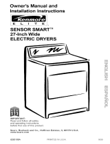
• Support: Floor must be sturdy enough to
support a total weight of 115 pounds
(includes dryer and load weight).
• Location: Must be large enough to fully
open dryer door. See “Recessed area and
closet installation” for minimum spacing
requirements.
• Level floor: 1-in maximum slope under
entire dryer.
NOTE: Observe all governing codes and
ordinances.
20
3
⁄4"
31"
23
7⁄8
"
3977625v09c27 4/1/99 4:45 PM Page 5

6
How to install your dryer
Now that you’ve unpacked your dryer, check
to be sure you have removed the parts bag
from the drum. Remove the tape that holds
the drum to the cabinet. Move the drum by
hand to make certain all tape has been
removed. Next, wipe the interior of the drum
thoroughly with a damp cloth before using
the dryer.
Installation
To install your dryer, you will need the tools
shown. All the parts you need are packed in
the appliance. When you take them out,
place them on a cloth so you won’t lose
them.
Parts supplied with the dryer:
1 Cycle and temperature control (timer)
knob
1 Push to Start button
4 Leveling legs
Adjustable
wrench
Level Flashlight
(optional)
1
⁄4-inch
nut driver
#2 Phillips
head
screwdriver
Wire
stripper
Duct
tape
Flat-head
screwdriver
INSTALLATION INSTRUCTIONS
3977625v09c27 4/1/99 4:45 PM Page 6

7
1. Take two of the cardboard corners from
the carton. Place them on the floor in back
of the dryer.
2. Firmly grasp the body of the dryer. Gently
lay dryer on the cardboard corners.
3. Start to screw the legs into the holes by
hand. Use a wrench to finish turning the
legs. They should stick out about 1 inch.
4. Now stand the dryer up and move it close
to its final location. Leave enough room to
connect the exhaust vent.
5. Check levelness of dryer by placing a level
on top of the dryer, first side-to-side; then
front-to-back.
6. If dryer is not level, prop the dryer up
using two stacked cardboard corner posts.
Use a wrench to adjust the legs up or
down.
NOTE: It may be necessary to level the
dryer again after it is moved into its final
position.
WARNING
Excessive Weight Hazard
Use two or more people to move and
install dryer.
Failure to do so can result in back or
other injury.
Installing the leveling legs
Leveling your dryer correctly will reduce
operating noise and provide improved drying
performance.
To install leveling legs:
INSTALLATION INSTRUCTIONS
3977625v09c27 4/1/99 4:45 PM Page 7

8
INSTALLATION INSTRUCTIONS
Electrical Requirements
A three-wire or four-wire, single phase
120/240-volt, 60-Hz., AC-only, electrical
supply is required on a separate 30-ampere
circuit, fused on both sides of the line. A
time-delay fuse or circuit breaker is
recommended.
This dryer is manufactured with the 3-wire,
frame-grounding conductor connected to the
NEUTRAL (center) of the wiring harness of
the terminal block. Do not have a fuse in the
neutral or grounding circuit. A fuse in the
neutral or grounding circuit could result in an
electrical shock.
Use a 4-conductor cord when the dryer is
installed in a mobile home or an area where
local codes do not permit grounding through
the neutral.
If Your Home Has:
3-wire electrical
receptacle
(NEMA Type 10-30R)
3-wire direct
4-wire electrical
receptacle
(NEMA Type 14-30R)
4-wire direct
A U.L.-listed, 120/240-volt
minimum, 30-amp., dryer
power supply cord.*
A fused disconnect or
circuit breaker box.*
A U.L.-listed, 120/240-volt
minimum, 30-amp., dryer
power supply cord.
A fused disconnect or
circuit breaker box.
11
And You Will Be
Connecting To:
14
16
9
3
1
/2"
5"
Electrical Connection Options
*If local codes do not permit the connection of a frame-grounding conductor to the neutral wire, see the
instructions for “Alternate Connection”.
Go To
Page:
5"
3977625v09c27 4/1/99 4:45 PM Page 8

9
Three-Wire Electrical Connection to Receptacle
• Do not use an extension cord with
this dryer.
• Do not connect plug end of power supply
cord into a live receptacle before
connecting power supply cord to dryer
terminal block.
Local codes may permit the use of a U.L.-
listed, 120/240-volt minimum, 30-ampere,
dryer power supply cord kit (pigtail). Power
supply cord should be type SRD or SRDT
and be at least four feet long. The wires that
connect to the dryer must end with ring
terminals or spade terminals with upturned
ends.
NEUTRAL
This blade connected
to this conductor
NEUTRAL
(white or center)
3
⁄4", U.L.-listed,
strain relief
Spade terminals
with upturned ends
Ring
terminals
• The power supply cord must have three,
No.-10 copper wires to match a three-wire
receptacle of NEMA Type 10-30R.
INSTALLATION INSTRUCTIONS
GROUNDING INSTRUCTIONS
This appliance must be grounded.
In the event of malfunction or breakdown,
grounding will reduce the risk of electric
shock by providing a path of least
resistance for electric current. The power
supply cord must be plugged into an
appropriate outlet that is properly installed
and grounded in accordance with all local
codes and ordinances.
WARNING: Improper connection of the
equipment-grounding conductor can result
in a risk of electric shock.
Check with a qualified electrician or
serviceman if you are in doubt as to
whether the appliance is properly
grounded. Do not modify the plug on the
power supply cord. If it will not fit the
outlet, have a proper outlet installed.
SAVE THESE INSTRUCTIONS
Three-wire
receptacle (NEMA
Type 10-30R)
wWARNING
Fire Hazard
Use a new UL approved 30 ampere
power supply cord.
Use a UL approved strain relief.
Disconnect power before making
electrical connections.
Connect neutral wire (white or center
wire) to center terminal (silver).
Ground wire (green or bare wire) must
be connected to green ground
connector.
Connect remaining 2 supply wires to
remaining 2 terminals (gold).
Securely tighten all electrical
connections.
Failure to do so can result in death,
fire, or electrical shock.
3977625v09c27 4/1/99 4:45 PM Page 9

10
1. Disconnect power.
2. Remove hold-down screw and terminal
block cover.
3. Attach a
3
⁄4-inch, U.L.-listed, strain relief to
the hole below terminal block opening.
Strain relief should have a tight fit with
dryer cabinet and be in a horizontal
position. Put the power supply cord
through the strain relief.
4. Loosen or remove terminal block screws.
Connect the neutral wire (white or center)
of power supply cord under the center
screw of the terminal block.
5. Connect the other two wires to outer
terminal block screws. Tighten all terminal
block screws firmly.
6. Tighten the strain relief screws.
7.Insert tab of terminal block cover into slot
of the dryer rear panel. Secure cover with
hold-down screw.
NOTE: If local codes do not permit the
connection of a frame-grounding conductor
to the neutral wire, see the instructions for
“Alternate Connection” later in this section.
Neutral ground-
ing wire
(green/yellow)
3
⁄4 ", U.L.-listed,
strain relief
Neutral
wire
(white)
Center silver-colored
terminal block screw
External ground
connector
3-Wire Connection with
Frame-Grounding Conductor
INSTALLATION INSTRUCTIONS
Terminal block cover
Hold-down screw
3977625v09c27 4/1/99 4:45 PM Page 10

11
1"
3
1
/
2
"
The dryer can be connected directly to fused
disconnect or circuit breaker box with three-
wire, flexible armored or non-metallic
sheathed copper cable (with grounding wire).
All current-carrying wires must be insulated.
A conduit connector must be installed at
junction box. Allow four feet of slack in the
line so dryer can be moved if servicing is
ever necessary.
1. Disconnect power.
• Strip 3
1
⁄2 inches of outer covering from
end of cable.
• Cut 1 inch of insulation from the end of
each insulated wire. Shape the end of
each wire into a “U” shaped hook.
3
1
/2"
Three-Wire Electrical Connection (Direct Wire)
INSTALLATION INSTRUCTIONS
GROUNDING INSTRUCTIONS
This appliance must be connected to a
grounded metal, permanent wiring system;
or an equipment-grounding conductor
must be run with the circuit conductors and
connected to the equipment-grounding
terminal or lead on the appliance.
SAVE THESE INSTRUCTIONS
wWARNING
Fire Hazard
Use 10 gauge solid copper wire.
Use a UL approved strain relief.
Disconnect power before making
electrical connections.
Connect neutral wire (white or center
wire) to center terminal (silver).
Ground wire (green or bare wire) must
be connected to green ground
connector.
Connect remaining 2 supply wires
to remaining 2 terminals (gold).
Securely tighten all electrical
connections.
Failure to follow these instructions can
result in death, fire, or electrical shock.
continued on next page
3977625v09c27 4/1/99 4:45 PM Page 11

12
2. Remove hold-down screw and terminal
block cover.
3. Attach a
3
⁄4-inch, U.L.-listed, strain relief to
the hole below terminal block opening.
Strain relief should have a tight fit with
dryer cabinet and be in a horizontal
position. Put the direct wire cable through
the strain relief.
4. Loosen or remove terminal block screws.
Connect the neutral wire (white or center)
of direct wire cable under the center screw
of the terminal block.
• Place the hook-shaped end of the wire
over the terminal block screw. The open
side of the hook should face to the right.
Squeeze hook end of wire together to
form a loop.
Center silver-colored
terminal block screw
Neutral
wire
(white)
External ground
connector
Neutral grounding
wire (green/yellow)
3
⁄4 ", U.L.-listed,
strain relief
3-Wire Connection with Direct Wire
and Frame-Grounding Conductor
INSTALLATION INSTRUCTIONS
Terminal block cover
Hold-down screw
3977625v09c27 4/1/99 4:46 PM Page 12

13
Alternate Connection:
If local codes do not permit the connection of
a frame-grounding conductor to the neutral
wire:
1. Disconnect power.
2. Make sure the power supply cord or direct
wire cable is in place (see steps 1-3 on
page 10 for power cord connections or
steps 1-3 on pages 11 and 12 for direct
wire connection).
3. Remove the neutral grounding wire
(green/yellow wire) from external ground-
ing connector screw. Loosen or remove
terminal block screws. Connect neutral
grounding wire and the neutral wire (white
or center) of power supply cord or direct
wire cable under the center screw of the
terminal block.
4. Connect the other two wires to outer termi-
nal block screws. Tighten all terminal block
screws firmly.
5. Tighten the strain relief screws.
6. Insert tab of terminal block cover into slot
of the dryer rear panel. Secure cover with
hold-down screw.
7. Connect separate copper grounding wire
from external ground connector to an
adequate ground. If codes permit and a
separate grounding wire is used, it is
recommended that a qualified electrician
determine that the grounding path is
adequate.
Grounding path
determined by a
qualified electrician
External
ground
connector
Neutral
grounding wire
(green/yellow)
Alternate 3-Wire Connection with
External-Grounding Conductor
INSTALLATION INSTRUCTIONS
5. Connect the other two wires to outer
terminal block screws using the same
method(s) described in step 4. Tighten all
terminal block screws firmly.
6. Tighten the strain relief screws.
7. Insert tab of terminal block cover into slot
of the dryer rear panel. Secure cover with
hold-down screw.
NOTE: If local codes do not permit the
connection of a frame-grounding conductor
to the neutral wire, see the instructions for
“Alternate Connection.”
3977625v09c27 4/1/99 4:46 PM Page 13

14
Make Four-Wire Electrical Connection to Receptacle
Local codes may permit the use of a
U.L.-listed, 120/240-volt minimum, 30
ampere, dryer power supply cord kit (pigtail).
Power supply cord should be type SRD or
SRDT and be at least four feet long. The
wires that connect to the dryer must end
with ring terminals or spade terminals with
turned ends.
Four-Wire Power Supply Cord
(Mobile home or other four-wire installations)
For mobile homes or other four-wire
installations, the power supply cord must
have four, No.-10 copper wires and match a
four-wire receptacle of NEMA Type 14-30R.
The fourth wire (grounding conductor) must
be identified with a green cover or bare
copper wire and the neutral conductor by a
white cover.
Ring
terminals
Grounding
wire (green)
Grounding
prong
3
⁄4 ", U.L.-listed,
strain relief
NEUTRAL
(white)
NEUTRAL
Four-wire receptacle
(NEMA Type 14-30R)
INSTALLATION INSTRUCTIONS
GROUNDING INSTRUCTIONS
This appliance must be grounded. In the
event of malfunction or breakdown,
grounding will reduce the risk of electric
shock by providing a path of least
resistance for electric current. The power
supply cord must be plugged into an
appropriate outlet that is properly
installed and grounded in accordance
with all local codes and ordinances.
WARNING: Improper connection of
the equipment-grounding conductor can
result in a risk of electric shock. Check
with a qualified electrician or serviceman
if your are in doubt as to whether the
appliance is properly grounded.
Do not modify the plug on the power
supply cord. If it will not fit the outlet,
have a proper outlet installed by a
qualified electrician.
SAVE THESE INSTRUCTIONS
wWARNING
Fire Hazard
Use a new UL approved 30 ampere
power supply cord.
Use a UL approved strain relief.
Disconnect power before making
electrical connections.
Connect neutral wire (white or center
wire) to center terminal (silver).
Ground wire (green or bare wire) must
be connected to green ground
connector.
Connect remaining 2 supply wires to
remaining 2 terminals (gold).
Securely tighten all electrical
connections.
Failure to do so can result in death, fire,
or electrical shock.
• Do not use an extension cord with this
dryer.
• Do not connect plug end of power supply
cord into a live receptacle before
connecting power supply cord to dryer
terminal block.
3977625v09c27 4/1/99 4:46 PM Page 14

15
1. Disconnect power.
2. Remove hold-down screw and terminal
block cover.
3. Attach a
3
⁄4-inch, U.L.-listed, strain relief to
the hole below terminal block opening.
Strain relief should have a tight fit with
dryer cabinet and be in a horizontal
position. Put the power supply cord
through the strain relief.
4. Remove the center terminal block screw.
Remove the neutral grounding wire
(green/yellow wire) from external
grounding screw.
5. Connect neutral grounding wire and the
neutral wire (white) of power supply cord
under the center screw of terminal block.
6. Connect the other two insulated wires to
outer terminal block screws.
7. Connect the green, grounding wire from
the power supply cord to the external
grounding conductor screw. Tighten all
terminal block screws firmly.
8. Tighten the strain relief screws.
9. Insert tab of terminal block cover into slot
of the dryer rear panel. Secure cover with
hold-down screw.
Center silver-colored
terminal block screw
External ground
connector
Green/yellow wire
of harness
External
ground
connector
Neutral wire
(white)
Center silver-colored
terminal block screw
Green wire
of power supply
cord or bare
copper wire
Neutral ground-
ing wire
(green/yellow)
3
⁄4”, U.L.-listed,
strain relief
4-Wire Connection with
Frame-Grounding Conductor
Terminal block cover
Hold-down screw
INSTALLATION INSTRUCTIONS
3977625v09c27 4/1/99 4:46 PM Page 15

16
Four-Wire Electrical Connection (Direct Wire)
The dryer can be connected directly to fused
disconnect or circuit breaker box with
four-wire, flexible armored or non-metallic
sheathed copper cable (with grounding wire).
All current-carrying wires must be insulated.
The grounding wire may be bare.
A conduit connector must be installed at
junction box. Allow four feet of slack in the
line so dryer can be moved if servicing is
ever necessary.
1. Disconnect power.
• Strip 5 inches of outer covering from
end of cable. Leave bare grounding wire
at 5 inches.
• Cut 1 inch from 3 remaining
insulated wires. Strip insulation back 1
inch. Shape the end of each wire into a
“U” shaped hook.
2. Remove hold-down screw and terminal
block cover.
5"
1"
5"
INSTALLATION INSTRUCTIONS
GROUNDING INSTRUCTIONS
This appliance must be connected to a
grounded metal, permanent wiring
system; or an equipment-grounding
conductor must be run with the circuit
conductors and connected to the
equipment-grounding terminal or lead
on the appliance.
SAVE THESE INSTRUCTIONS
Terminal block cover
Hold-down screw
5"
5"
wWARNING
Fire Hazard
Use 10 gauge solid copper wire.
Use a UL approved strain relief.
Disconnect power before making
electrical connections.
Connect neutral wire (white or center
wire) to center terminal (silver).
Ground wire (green or bare wire) must
be connected to green ground
connector.
Connect remaining 2 supply wires
to remaining 2 terminals (gold).
Securely tighten all electrical
connections.
Failure to follow these instructions can
result in death, fire, or electrical shock.
3977625v09c27 4/1/99 4:46 PM Page 16

17
Center silver-colored
terminal block screw
External ground
connector
Neutral
grounding wire
(green/yellow)
3
⁄4”, U.L.-listed,
strain relief
Neutral wire (white)
Bare copper wire
4-Wire Connection with Direct Wire and
Frame-Grounding Conductor
3. Attach a
3
⁄4-inch, U.L.-listed, strain relief to
the hole below terminal block opening.
Strain relief should have a tight fit with
dryer cabinet and be in a horizontal
position. Put the direct wire cable through
the strain relief.
4. Remove the center terminal block screw.
Remove the neutral grounding wire
(green/yellow wire) from external
grounding screw.
5. Connect neutral grounding wire and the
neutral wire (white or center) of direct
wire cable under the center screw of
terminal block.
6. Place the hook-shaped end of the wire
over the terminal block screw. The open
side of the hook should face to the right.
Squeeze hook end of wire together to
form a loop.
7. Connect the other two wires to outer
terminal block screws. Use the same
method described in Step 6.
8. Connect the direct wire cable (bare)
grounding wire to the external-grounding
conductor screw. Tighten all terminal
block screws firmly.
9. Tighten the strain relief screws.
10. Insert tab of terminal block cover into slot
of the dryer rear panel. Secure cover with
hold-down screw.
Green/yellow wire
of harness
External ground
connector
Center silver-colored
terminal block screw
INSTALLATION INSTRUCTIONS
(Steps 6-7)
3977625v09c27 4/1/99 4:46 PM Page 17

18
INSTALLATION INSTRUCTIONS
Exhaust requirements
Your dryer must be properly vented to
achieve maximum drying efficiency.
WARNING: To reduce the risk of fire,
this dryer MUST BE EXHAUSTED
OUTDOORS.
• Do not exhaust dryer into a chimney, a
wall, a ceiling, or a concealed space of a
building.
• The diameter of the heavy metal vent must
be 4-in.
• Do not use an exhaust hood with a
magnetic latch.
If using an existing exhaust system, remove
accumulated lint.
1. Disconnect vent from the dryer and clean
one section at a time until you reach the
exhaust hood.
2. Use the hose attachment on your vacuum,
or a pole with a feather duster or rag
attached, to clean out lint.
3. Be sure the flapper on the outside end of
vent moves freely. Make sure exhaust
hood is not plugged with lint.
Clean exhaust vent periodically, depending
on use, but at least every 2 years, or when
installing your dryer in a new location.
wWARNING
Fire Hazard
Use a heavy metal vent.
Do not use a plastic vent.
Do not use a metal foil vent.
Failure to follow these instructions
can result in death or fire.
3977625v09c27 4/1/99 4:46 PM Page 18

19
INSTALLATION INSTRUCTIONS
Use duct tape to seal all joints. Do not use
screws to secure vent. Lint may catch on
screws.
Use 4-inch heavy metal vent. Do not kink or
crush flexible metal vent. It must be fully
extended to allow adequate exhaust air to
flow. Check vent after installation.
Use the straightest path possible when
routing the exhaust vent. Use the fewest
number of elbows and turns. Allow as much
room as possible when using elbows or
making turns. Bend vent gradually to avoid
kinking. Remove excess flexible vent to
avoid sagging and kinking that may result in
reduced airflow.
Maximum length of the exhaust system
depends upon the type of vent used,
number of elbows, and the type of exhaust
hood. The maximum length for both heavy
and flexible vent is shown on the next page.
Exhaust outlet at rear of dryer is located as
illustrated. Detailed instructions on spacing
for side and rear clearances can be found in
the “Recessed area and closet installation”
section.
Better
Good
Exhaust airflow
12" 4" DIAM
3
1
/4"
Rear
exhaust
outlet
3977625v09c27 4/1/99 4:46 PM Page 19

20
4"
Determining vent length
No. of
90°
turns
Heavy Metal Vent 4-inch diameter
Maximum length
0 36 ft 36 ft 26 ft
1 26 ft 26 ft 16 ft
2 16 ft 16 ft 6 ft
EXHAUST HOOD TYPE
4"
2
1
⁄
2
"
Flexible Metal Vent
4-inch diameter
Maximum length
0 28 ft 28 ft 22 ft
1 18 ft 18 ft 12 ft
2 8 ft 8 ft 2 ft
NOTE: Check periodically to ensure that
the outside exhaust hood is not blocked.
The maximum length of the exhaust system
depends upon:
• The type of vent (heavy or flexible metal).
• The number of elbows (90° turns) used.
To determine maximum vent length:
1. See the Exhaust Hood Type chart that
matches your hood type for the maximum
vent lengths you can use.
Do not use vent runs longer than
specified in Exhaust Hood Type chart.
Exhaust systems longer than specified will:
• Shorten the life of the dryer.
• Reduce performance, resulting in
longer drying times and increased
energy usage.
2. Determine the number of elbows you will
need.
3. In the column listing the type of metal vent
you are using (heavy or flexible), find the
maximum length of metal vent on the
same line as the number of elbows.
Exhaust hood
Flexible metal vent or
heavy metal vent
Elbow
INSTALLATION INSTRUCTIONS
3977625v09c27 4/1/99 4:46 PM Page 20
/