Page is loading ...

MINI CHILLER INVERTER H6
English
CL25620 to CL25628
MUENR-H6 / MUENR-H6T
www.mundoclima.com
Installation & Owner's manual
and information requirements


1.2 Scope of this manual
READ THESE INSTRUCTIONS CAREFULLY BEFORE
INSTALLATION. KEEP THIS MANUAL IN A HANDY PLACE
FOR FUTURE REFERENCE.
IMPROPER
INSTALLATION OR ATTACHMENT OF
EQUIPMENT OR ACCESSORIES COULD RESULT IN
ELECTRIC SHOCKS, SHORT-CIRCUITS, LEAKS, FIRE OR
OTHER DAMAGE TO THE EQUIPMENT. BE SURE TO
ONLY USE ACCESSORIES MADE BY THE SUPPLIER
WHICH ARE SPECIFICALLY DESIGNED FOR USE WITH
THE EQUIPMENT AND HAVE INSTALLATION DONE BY A
PROFESSIONAL
ALL ACTIVITIES DESCRIBED IN THIS MANUAL SHALL BE
CARRIED OUT BY A LICENSED TECHNICIAN.
BE SURE TO WEAR ADEQUATE PERSONAL
PROTECTION SUCH AS GLOVES AND SAFETY GLASSES
WHEN PERFORMING INSTALLATION, MAINTENANCE
OR SERVICE TO THE UNIT.
IF UNSURE OF INSTALLATION PROCEDURES OR USE,
CONTACT YOUR DEALER FOR GUIDANCE
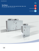
■ Operation range
(*)
The unit can not operate in cold weather conditions below -15 . If
it is necessary to operate, an external auxiliary heat source must
be added as a backup heater. the backup heater also serves as a
backup in case of malfunctioning of the unit and for freeze
ptrotection of the outside water piping during winter time.
These models have an antifreeze function that allows the use of
heat pumps to keep the water system free from freezing under all
conditions. If there is an accident or intentional power outage, it is
recommended to use ethylene glycol.
2. ACCESSORIES
2.1 Accessories supplied with the unit
1.1 General information
■
These units are used for both heating and cooling applications.
They can be combined with fan coil units, floor heating
applications (connect the mixed station), low temperature high
efficiency radiators (field supply).
■
The host unit controller is standard supplied with the unit to control
the system.
■ A wired remote controller can also be used to control the system
(Optional).
1. INTRODUCTION
CONTENTS PAGE
1. INTRODUCTION................................................................... 1
2. ACCESSORIES..................................................................... 1
3. SAFETY CONSIDERATIONS............................................... 2
4. OVERVIEW OF THE UNIT.................................................... 3
5. UNIT INSTALLATION........................................................... 11
6 START-UP AND CONFIGURATION.................................... 25
7. THE HOST UNIT CONTROLLER ELUCIDATION............... 27
8. TROUBLE SHOOTING......................................................... 31
9. IMPORTANT INFORMATION FOR THE USED
REFRIGERANT..................................................................... 32
10. MAIN PARAMETERS......................................................... 33
HEATING MODE
DELIVERY WATER TEMPERATURE
OUTSIDE AIR TEMPERATURE
35 54
-15
0
27
t(°C)
t(°C)
40
2
1
1
1
Shape
Qty
.Unit
Outflow connecting
tube (for the chassis)
Straight screwdriver
1
Y-shaped filter
Installation &
Owner’s Manual
Rubber ring for wires
(only 10~16kW)
COOLING MODE
DELIVERY WATER TEMPERATURE
OUTSIDE AIR TEMPERATURE
4 7 15 20
-5
35
46
t(°C)
t(°C)
This installation & ow
ner's man
ual does not
include the selection
procedure and water system design procedure. Only some
precautions and tips and tricks about the design of the water circuit
are given in a separate chapter of this manual. Once the selection is
done and the water system is designed, this manual describes the
procedures for handing, installing and connecting the unit, This
manual has been prepared to ensure adequate maintenance of the
unit, and it will provide help if problems occur.
This unit is designed to cool/heat water and must be
used in applications compatible with its performance
characteristics, i.e. residential or commercial applications
combined with a fan coil unit, low temperature radiators
and underfloor heating. It should never be used for
underfloor cooling, as doing so may damage the plate
heat exchanger.
1

3. SAFETY CONSIDERA
TIONS
The precautions listed here are divided into the following types.
They are quite important, so be sure to follow them carefully.
Meanings of DANGER, WARNING, CAUTION and NOTE symbols.
DANGER
Indicates an imminently hazardous situation which if not
avoided, will result in death or serious injury.
WARNING
Indicates a potentially hazardous situation which if not
avoided, could result in death or serious injury.
CAUTION
Indicates a potentially hazardous situation which, if not
avoided, may result in minor or moderate injury. It is also
used to alert against unsafe practices.
NOTE
Indicates situations that could only result in accidental
equipment or property damage.
■ Before touching electric terminal parts, turn off power switch.
■ When service panels are removed, live parts can be easily
touched by accident.
Never leave the unit unattended during installation or servicing
when the service panel is removed.
■ Do not touch water pipes during and immediately after operation
as the pipes may be hot and could burn your hand. To avoid injury,
give the piping time to return to normal temperature or be sure to
wear protective gloves.
■ Do not touch any switch with wet fingers. Touching a switch with
wet fingers can cause electrical shock.
■ Before touching electrical parts, turn off all applicable power to
the unit.
DANGER
W
ARNING
■ Tear apart and throw away plastic packaging bags so that children
will not play with them.
Children playing with plastic bags face danger of death by
suffocation.
■ Safely dispose of packing materials such as nails and other metal
or wood parts that could cause injuries.
■ Ask your dealer or qualified personnel to perform installation work
in accordance with this manual. Do not install the unit yourself.
Improper installation could result in water leakage, electric shocks
or fire
■ Be sure to use only specified accessories and parts for installation
work.
Failure to use specified parts may result in water leakage, electric
shocks, fire, or the unit falling from its mount.
■ Install the unit on a foundation that can withstand its weight.
■ Insufficient physical strength may cause the equipment to fall and
possible injury
■ Perform specified installation work with full consideration of strong
wind, hurricanes, or earthquakes.
Improper installation work may result in accidents due to equipment
falling.
■ Make certain that all electrical work is carried out by qualified
ersonnel according to the local laws and regulations and this
manual using a separate circuit.
Insufficient capacity of the power supply circuit or improper electrical
construction may lead to electric shocks or fire.
■ Be sure to install a ground fault circuit interrupter according to local
laws and regulations.
Failure to install a ground fault circuit interrupter may cause electric
shocks and fire.
■ Make sure all wiring is secure. Use the specified wires and ensure
that terminal connections or wires are protected from water and
other adverse external forces.
Incomplete connection or affixing may cause a fire.
■ When wiring the power supply, form the wires so that the front panel
can be securely fastened.
If the front panel is not in place there could be overheating of the
terminals, electric shocks or fire.
■ After completing the installation work, check to make sure that there
is no refrigerant leakage.
■ Never directly touch any leaking refrigerant as it could cause severe
frostbite.
■ Do not touch the refrigerant pipes during and immediately after
operation as the refrigerant pipes may be hot or cold, depending on
the condition of the refrigerant flowing through the refrigerant piping,
compressor and other refrigerant cycle parts. Burns or frostbite are
possible if you touch the refrigerant pipes. To avoid injury, give the
pipes time to return to normal temperature or, if you must
touchthembe sure to wear protective gloves.
■ Do not touch the internal parts (pump, etc.) during and immediately
after operation.
Touching the internal parts can cause burns. To avoid injury, give
the internal parts time to return to normal temperature or, if you must
touch them, be sure to wear protective gloves.
CAUTION
■ Ground the unit.
Grounding resistance should be according to local laws and
regulations
Do not connect the ground wire to gas or water pipes,
lightning conductors or telephone ground wires.
Incomplete grounding may cause electric shocks.
a) Gas pipes.
Fire or an explosion might occur if the gas leaks.
b) Water pipes.
Hard vinyl tubes are not effective grounds.
c) Lightning conductors or telephone ground wires.
Electrical threshold may rise abnormally if struck by a lightning bolt.
■ Install the power wire at least 3 feet (1 meter) away from
televisions or radios to prevent interference or noise. (Depending
on the radio waves, a distance of 3 feet (1 meter) may not be
sufficient to eliminate the noise.)
■ Do not wash the unit. This may cause electric shocks or fire. The
appliance must be installed in accordance with national wiring
regulations. If the supply cord is damaged, it must be replaced by
the manufacturer, its service agent or similarly qualified persons in
order to avoid a hazard.
■ Do not install the unit in the following places:
a) Where there is mist of mineral oil, oil spray or vapors.
Plastic parts may deteriorate, and cause them to come
loose or water to leak.
b) Where corrosive gases (such as sulphurous acid gas) are
produced.
Where corrosion of copper pipes or soldered parts may cause
refrigerant to leak.
2

c) Where there is machinery which emits electromagnetic waves.
Electromagnetic waves can disturb the control system and
cause equipment malfunction.
d) Where flammable gases may leak, where carbon fiber or
ignitable dust is suspended in the air or where volatile
flammables such as paint thinner or gasoline are handled.
These types of gases might cause a fire.
e) Where the air contains high levels of salt such as near the
ocean.
f) Where voltage fluctuates a lot, such as in factories.
g) In vehicles or vessels.
h) Where acidic or alkaline vapors are present.
■ This appliance can be used by children 8 years old and above and
persons with reduced physical, sensory or mental capabilities or
lack of experience and knowledge if they are supervised or given
instruction on using the unit in a safe manner and understand the
hazards involved. Children should not play with the unit. Cleaning
and user maintenance should not be done by children without
supervision.
■ Children
should be supervised to ensure that they do not play with
the appliance.
■ If the supply cord is damaged, it must be replaced by the manufaturer
or its service agent or a similarly qualified person.
■ DISPOSAL: Do not dispose this product as unsorted municipal
waste. Collection of such waste seperatelly for special treatment is
necessary.
Do not dispose of electrical appliances as municipal waste, use
seperate collection facilities.
Contact your local goverment for information regarding the
collection systems available.
If electrical appliances are disposed of in landfills or dumps,
hazardous substance can leak into the groudwater and get into the
food chain, damaging your health and well-being.
■ The wiring
must be performed by professional technicians in
accordance with national wiring regulation and this circuit diagram.
An all-pole disconnection device which has at least 3mm
seperation distance in all pole and a residualcurrent device(RCD)
with the rating not exceeding 30mA shall be incorporated in the
fixed wiring according to the national rule.
1 Operation panel
2 4-ways valve
3 Storage tank
4 Pump
5 Electric expansive valve
6 Compressor
7 Air purge valve
8 Electrical control box
9 Water manometer
10 Expansion tank
11 Plate heat exchanger
12 Condenser
13 Axial-flow fan
14 Adapter substitute
(accessory)
15 Security discharge
16 Auto-water replenishing
valve (accessory)
17 Water flow switch
18 High pressure switch
19 Low pressure switch
1
2
11
12
13
3
4
5
6
7
8
9
10
14
15
16
17
18
19
4. OVERVIEW OF THE UNIT
1 Operation panel
2 Water manometer
3 Air purge valve
4 Axial-flow fan
5 Differential pressure switch
6 Condenser
7 Accumulater
8 Security discharge
9 Electric expansive valve
10 Plate heat exchanger
11 Electrical control box
12 High pressure switch
13 4-ways valve
14 Expansion tank
15 Pump
16 Low pressure switch
17 Storage tank
18 Compressor
19 Auto-water replenishing
valve
1
5
7
8
9
10
11
12
13
14
15
16
17
18
19
2
3
4
6
4.1 Main par
ts of the unit
4.2 Unit connections
5/7kW
10~16kW
1 Water inlet
2 Water outlet
3 Auto-watet replenishing orifice
4 Water outlet of safety Valve
5 Wire hole
1
3
2
4
5
3

4.3 Refrigerant cycle
4.4 Electrical control box introduce
4.4.1 5/7kW (1-phase)
The electrical control box is located inside the unit at the top of
the technical compartment where the various components
of the refrigerant circuit are also to be found.
To access the electrical panel,remove the front panel of
the unit by undoing the screws.
PL
PH
1 3
52
2
4
7
8
8
5
9
62
01
2
1
31
41
51
61
71
8
1
gnilooC
gnita
e
H
91
0
2
12
22
32
42
A
F
11
6
1 Compressor
2 4-W
ay Valve
3 Gas-liquid Separator
4 Air Side Heat Exchanger (condenser)
5 Electronic Expansion Valve
6 Capillary (only 5/7kW)
7 Storage Tank
8 Strainer
9 Water Side Heat Exchanger
(Plate Heat Exchange)
10 Differential Pressure Switch (only 10~16kW)
11 Flow Switch (only 5/7kW)
12 Thermistor For Discharge Temperature
13 Thermistor For Outdoor Temperature
14 Thermistor For Evaporation In Heating
(Thermistor For Condenser In Cooling)
15 Thermistor For Plate Heat Exchange 1
16 Thermistor For Plate Heat Exchange 2
17 Thermistor For Water Outlet
18 Thermistor For Water Inlet
19 Air purge Valve
20 Expansion Tank
21 Circulating Pump
22 Water manometer
23 Safety Valve
24 Auto-watet replenishing valve
25 High Pressure Switch
26 Low Pressure Switch
4

2. PFC&IPM module board (The picture is for reference only)
1.Input rectifier bridge port 1
2.Input rectifier bridge port 2
3.PFC inductance port 1
4.P-OUT
5.PFC inductance port 2
6.N-OUT
7.PFC control port
8.+18V port
9.IPDU communication port
10.IPM power port N
1
1.Compressor connection port U/V/W
12.IPM power port P
3. DC filter board (The picture is for reference only)
1.IPM Power supply P
2.IPM Power supply N
3.PFC output power N
4.PFC output power P
5.DC 380V (DC fan power supply port)
1. ELECTRICAL PANEL LAYOUT
① Main control board
② DC filter board
③ IPM & PFC module board
④ FC inductance
⑤ Transformer
⑥ Display board
⑦ Customer connection terminal
④ ③ ② ① ⑦
⑤
⑥
(The picture below shows the position of the diagram, please participate in the concrete photos)
5
4
1
2
3
5

4. Main control board (The picture is for reference only)
1.Power L
2.Power N
3.Preliminary charging relay (rectifier bridge input port 1)
4.Input rectifier bridge line (rectifier bridge input port 2)
5.5A
fuse
6.To IPDU
7.To PFC
8.Solenoid valve (Reserve)
9.Electric heater of plate heat exchanger
10.Electric heater of compressor
11.Pump
12.Electric heater of exhaust valve
13.Electric heater of water flow switch
14.4-way valve
15.Additional pump/Remote alarm port
16.Transformer input
17.Electronic expansion valve
18.DC fan power supply port
19.DC fan port
20.Remote control port
21.Force cooling switch
22.Parameter checking switch
23.Tin/Tout/Tb1 temperature sensor
24.Discharge temperature sensor (Tp)
25.1 Outlet of outdoor heat exchanger temperature sensor (T3)
25.2 Ambient temperature sensor(T4)
26.1 Low pressure switch
26.2 High pressure switch
27.Operation and display panel port
28.Water flow switch
29.Transformer output
30.Wired controller port
4.4.2 10~12kW (1-phase)
Remove the inspection panel by unscrewing the five screws. The
electric control box is located inside the unit at the top of the technical
components.
1. Use grommet A for the electrical power cable and grommet B
for the other external wires.
(The picture below shows the position of the diagram, please
participate in the concrete photos)
A
B
①
②
① Main control board ② PFC&IPM module board
30
6

2. Main control board (The picture is for reference only)
1.T
ransformer output port
2.Tin/Tb1/Tout/Tb2 temperature sensor port
Note: Tin: water inlet temp. Tout: water outlet temp.
Tb1: Temp. 1 of plate heat exchanger
Tb2: Temp.2 of plate heat exchanger
3. Radiator temperature sensor port(Reserved) (T6)
4. Discharge temperature sensor port
5.1 Outlet of outdoor heat exchanger temp. sensor port(T3)
5.2 Ambient temp. sensor port (T4)
6.Operation and display panel port
7.1 Low pressure switch
7.2 High pressure switch
8.Differential pressure valve port
9.Factory debug port
10.Wired controller port
11.Electric expansion valve port
12.Power supply input port L
13.Power supply input port N
14.Ground wire
15.Rectifier bridge input port N
16. Rectifier bridge input port L
17. 8A fuse tube
18. Solenoid valve port (Reserved)
19. Exhaust valve electric heater port
20. Plate heat exchanger electric heater port
21. Flow switch electric heater port
22. Built-in water pump port
23. Compressor electric heater port
24. 4-way valve port
25. External pump/Remote alarm port
26. Remote control port
27. Transformer input port
28. P/N/+15V port
29. Communication port between IPDU and main PCB
30. Down DC fan port
31. Check touch switch
32. Up DC fan port
33. Force-cooling touch switch
7

3. PFC&IPM module board (The picture is for reference only)
1. +18V output port
2. Input Port P
for IPM
3. Power supply port W
of the compressor
4. Power supply port V
of the compressor
5. Power supply port W
of the compressor
6. PFC output N
7. PFC output P
8. PFC inductance port L_1
9. PFC inductance port L_2
10. PFC input N
11. IPM input N
12. Communication port to
main control board
A
B
4.4.3 12~16kW (3-phase)
Remove the inspection panel by unscrewing the five screws.
The electric control box is located inside the unit at the top of the
technical components.
1. Use grommet A for the electrical power cable and grommet B for
the other external wires.
(The picture below shows the position of the diagram, please
participate in the concrete photos)
①
②
① Main control board ② IPM module board
8

2. Main control board (The picture is for reference only)
1. Input port for switching power supply
2. Debugging port
3. Connection port for operation and display panel
4.
Tin/Tb1/Tout/Tb2 temp. sensor port
Note: Tin: water inlet temp. Tout: water outlet temp.
Tb1: Temp.1 of plate heat exchanger
Tb2: Temp. 2 of plate heat exchanger
5. Discharged temperature sensor port (Tp)
6.1 T3 temperature sensor port
6.2 T4 ambient temperature sensor port
7.1. Low pressure switch
7.2 High pressure switch
8. Checking touch switch
9. Force-cooling touch switch
10. Differential pressure valve port
11. Factory debugging port
12. Wired controller port
13. AC Current transformer
14. Remote control port
15. Electronic expansion valve port
16. AC 220V power supply port
17. Solenoid valve port (Reserved)
18. Exhaust valve electric heater port
19. Electric heater port of Plate heat exchanger
20. Electric heater port of differential pressure valve
21. Built-in water pump port
22. Electric heater of the compressor
23. Precharge AC contactor port
24. 4-way valve port
25. External water pump/Remote alarm port
26. Up DC fan port
27. Down DC fan port
28. Power supply port for switching power supply of PFC board
29. Drive module port
30. P/N/+15V port
9

3. IPM module board (The picture is for reference only)
1. +15V output port
2. communication port to main
control board
3. IPM input port N
4. Compressor connection port W
1. Power supply port L3
2. Power supply port L2
3. Power input port L1
4. Power input port N
5. Ground wire
4. Filter board (The picture is for reference only)
6. Loaded power supply port for main control board
7. Power supply port for main control board
8. Power output port L1 after filtering
9. Power output port L2 after filtering
10.Power output port L3 after filtering
1
1. Ground wire
5. Compressor connection port V
6. Compressor connection port U
7. IPM input P
8. Power supply port for switching
power supply
10

5.1 Before installation
Before installation
Be sure to confirm the model name and the serial number of the unit.
Handling
Due to relatively large dimensions and heavy weight, the unit should
only be handled using lifting tools with slings. The slings can be fitted
into foreseen sleeves at the base frame that are made specifically for
this purpose.
■ To avoid injury, do not touch the
air inlet or aluminum fins of the unit.
■ Do not use the grips in the fan
grills to avoid damage.
■ The unit is top heavy! Prevent the
unit from falling due to improper
inclination during handling.
■ Be sure to provide for adequate measures in order to prevent
that the unit be used as a shelter by small animals.
■ Small animals making contact with electrical parts can cause
malfunctions, smoke or fire. Please instruct the customer to keep
the area around the unit clean.
Make sure there is enough room to do the installation
CAUTION
W
ARNING
1 Select an installation site where the following conditions
are satisfied and one that meets with your customer's approval.
- Places that are well-ventilated.
- Places where the unit does not disturb next-door neighbors.
- Safe places which can bear the unit's weight and vibration
and where the unit can be installed at an even level.
- Places where there is no possibility of flammable gas or product
leak.
- The equipment is not intended for use in a potentially explosive
atmosphere.
- Places where servicing space can be well ensured.
- Places where the units' piping and wiring lengths come within the
allowable ranges.
- Places where water leaking from the unit cannot cause damage
to the location (e.g. in case of a blocked drain pipe).
- Places where rain can be avoided as much as possible.
- Do not install the unit in places often used as a work space.
In case of construction work (e.g. grinding etc.) where a lot of dust
is created, the unit must be covered.
- Do not place any objects or equipment on top of the unit (top
plate)
- Do not climb, sit or stand on top of the unit.
- Be sure that sufficient precautions are taken in case of refrigerant
leakage according to relevant local laws and regulations.
2 When installing the unit in a place exposed to strong wind, pay
special attention to the following.
Strong winds of 5 m/sec or more blowing against the unit's air
outlet causes a short circuit (suction of discharge air), and this
may have the following consequences:
- Deterioration of the operational capacity.
- Frequent frost acceleration in heating operation.
- Disruption of operation due to rise of high pressure.
- When a strong wind blows continuously on the front of the unit,
the fan can start rotating very fast until it breaks.
Refer to the figures for installation of this unit in a place where the
wind direction can be foreseen.
■ Turn the air outlet side toward the building's wall, fence or screen.
3 Prepare a water drainage channel around the foundation, to drain
waste water from around the unit.
4 If water does not easily drain from the unit, mount the unit on a
foundation of concrete blocks, etc. (the height of the foundation
should be about 100 mm (3.93 in.).
5 If you install the unit on a frame, please install a waterproof plate
(about 100 mm) on the underside of the unit to prevent water from
coming in from the low side.
6 When installing the unit in a place frequently exposed to snow,
pay special attention to elevate the foundation
as high as possible.
7 If you install the unit on a building frame, please
install a waterproof plate (field supply)
(about 100 mm.) on the underside of the unit
in order to avoid drain water dripping.
(See figure).
■ Set the outlet side at a right angle to the direction of the wind.
Strong wind
Strong wind
Blown air
Blown air
5.2.1 Selecting a location in cold climates
When operating the unit in cold climates, be sure to
follow the instructions described below.
NOTE
Unit is top heavy!
Try not to install on the building frame.
NOTE
A
5-16kW
Unit A(mm)
≥2000
5. UNIT INSTALLATION
5.2 Selecting the installation site
11

■ To prevent exposure to wind, install the unit with its suction side
facing the wall.
■ Never install the unit at a site where the suction side may be
exposed directly to wind.
■ To prevent exposure to wind, install a baffle plate on the air
discharge side of the unit.
■ In heavy snowfall areas it is very important to select an installation
site where the snow will not affect the unit. If lateral snowfall is
possible, make sure that the heat exchanger coil is not affected by
the snow (if necessary construct a lateral canopy).
1 Construct a large canopy.
2 Construct a pedestal.
Install the unit high enough off the ground
to prevent it from being buried in snow.
5.2.2 Selecting a location in hot climates
As the outdoor temperature is measured via the outdoor unit air
thermistor, make sure to install the outdoor unit in the shade, or
a canopy should be constructed to avoild direct sunlight. so that
it is not influenced by the sun’s heat, otherwise protection may be
possible to the unit.
5.3 Installation space (Unit:mm)
>300
>600
>300
>2000
(W
all or obstacle)
Maintain
channel
Air outlet
Air inlet
Air inlet
Single unit installation
H
H
A
B
B
C
C
D
D
F
F
E
E
MODEL
(kW)
A
B E
D
G
FC
H
900 600 360 400
1327
348
10/12
/14/16
320
970
G
A
G
>2000 >500 >3000 >3000 >300
>600
>2000
>300
Parallel connect the two units or above
Parallel connect the front with rear sides
MODEL
(kW)
994 626 363 396
963
382
5/7
A
B E
D
G
FC
342
H
1008
12

All the pictures in this manual
are for explanation purpose only.
They may be slightly different from the air conditioner you
purchased(depend on model).The actual shape shall prevail.
NOTE
5.3.1 Moving and installation
>600
Fix with bolt
Do not touch the fan with hands or other objects.
Do not lean it more than 45°, and do not lay it sidelong.
Make concrete foundation according to the sepecifications of
the outdoor units.
Fasten the feet of this unit with bolts firmly to prevent it from
collapsing in case of earthquake or strong wind.
Since the gravity center of the unit is not at its physical center
,
so please be careful when lifting it with a sling.
Never hold the inlet of the outdoor unit to prevent it from
deforming.
5.3.2 W
ater Outlet
Reserve water outlet
Reserve water outlet
Water Outlet
(Need to knock open)
(With rubber stopper)
The condensed water outlets on the chassis for selection display
as the follow figure:
While installing the outdoor unit, pay attention to the installation
place and the drainage pattern;
If it’
s installed at the alpine zone, the frozen condensed water will
block up the water outlet, please pull out the rubber stopper of the
reserve water outlet (10~16kW). If that still fails to satisfy for the
water draining, please knock open the other water outlets (10~16kW),
and keep the water can drain in time.
Pay attention to the knock the reserve water outlet from outside to
inside, and it will be beyond repair after knocking open, please pay
attention to the installation place, lest cause the inconvenience.
Please do the moth proofing for the knocked out hole, to avoid the
pest processing into and destroy the components.
CAUTION
5/7kW
10~16kW
Water Outlet
13

5.4 TYPICAL APPLICATION EXAMPLES
Unit operation
NOTE
The application examples given below are for illustration purposes only.
5.4.1 Application 1
Space cooling and heating application with a standard controller (or optional wired controller) connected to the unit.
If the volume of balance tank(9) larger than 30L, the buffer tank(8) is unnecessary, otherwise the buffer tank(8) should be installed and the
total volume of buffer tank and balance tank should larger than 30L. The drain valve (6) should be installed at the lowest positon of the
system.
An independent backup heater can be selected and installed in the door,which can provide additional heating source and ensure better
performance of the system when the ambient temperature is low.
when there is a cooling or heating request from the standard controller (or optional wired controller), the unit will start operating to achieve
the target water flow temperature as set on standard controller (or optional wired controller). When the room temperature reaches the set point,
the unit will stop operating. The circulation pump (built-in pump 1 and outside pump 2) will also running.
4
11
10
12
32
6
7
8
9
1
FCUn
FCU2
FCU1
5
1 outdoor unit
2 Y-shape filter
3 shut-off valve (field supply)
4 wired controller (optional)
5
non-return valve (field supply)
6 drain valve (field supply)
7 fill valve (field supply)
8 buffer tank (field supply)
9 balance tank (field supply)
9.1 air purge valve
9.2 drain valve
10 expansion vessel (field supply)
11 Pump 2: outside circulation pump (field supply)
12 collector (field supply)
FCU 1...n fan coil units
14

5.4.2 Application 2
Space heating only application with a standard controller (or optional wired controller) connected to the unit. Heating is provided through floor
heating loops.
■ Mixing station
As the unit is mainly to provide middle-temperture and high-temperature water, when connecting floor heating, the need to increase the mixing
station (13) before the floor heating.
NOTE
If the volume of balance tank(9) larger than 30L, the buffer tank(8) is unnecessary, otherwise the buffer tank(8) should be installed and the
total volume of buffer tank and balance tank should larger than 30L.The drain valve (6) should be installed at the lowest positon of the
system.
An independent backup heater can be selected and installed in the door, which can provide additional heating source and ensure better
performance of the system when the ambient temperature is low.
FHL1 FHL2 FHLn
.......
11
10
12
32
6
7
8
9
4
22
13
5
1
1 outdoor unit
2 Y-shape filter
3 shut-off valve (field supply)
4 wired controller (optional)
5 non-return valve (field supply)
6 drain valve (field supply)
7 fill valve (field supply)
8 buffer tank (field supply)
9 balance tank (field supply)
9.1 air purge valve
9.2 drain valve
10 expansion vessel (field supply)
11 Pump 2: outside circulation pump (field supply)
12 collector (field supply)
13 mixing station (field supply, field control)
FHL 1...n floor heating loop
15

5.4.3 Application 3
Space cooling and heating application with a standard controller (or optional wired controller) connected to the unit. Heating is
provided through floor heating loops and fan coil units. Cooling is provided through the fan coil units only.
4
11
10
32
6
7
8
9
1
FHL1 FHL2 FHLn
FCUnFCU2FCU1
M
M2
T2
Mn
Tn
M1
T1
12
14
15
12
13
5
1 outdoor unit
2 Y-shape filter
3 shut-off valve (field supply)
4 wired controller (optional)
5 non-return valve (field supply)
6 drain valve (field supply)
7 fill valve (field supply)
8 buffer tank (field supply)
9 balance tank (field supply)
9.1 air purge valve
9.2 drain valve
■ Mixing station
As the unit is mainly to provide middle-temperture and high-temperature water, when connecting floor heating, the need to increase the mixing
station (13) before the floor heating.
NOTE
If the volume of balance tank(9) larger than 30L, the buffer tank(8) is unnecessary, otherwise the buffer tank(8) should be installed and the
total volume of buffer tank and balance tank should larger than 30L.The drain valve (6) should be installed at the lowest positon of the
system.
An independent backup heater can be selected and installed in the door, which can provide additional heating source and ensure better
performance of the system when the ambient temperature is low.
10 expansion vessel (field supply)
11 Pump 2: outside circulation pump (field supply)
12 collector (field supply)
13 mixing station (field supply, field control)
14 Motorised 2-way valve to shut off the floor heating loops during
cooling operation (field supply, field control)
15 by-pass valve (field supply)
FHL 1...n floor heating loop
FCU 1...n fan coil units
M1...n motorised valve to control loop FHL1...3 (field supply)
T1…n room thermostat (field supply)
■ Pump operation and space heating and cooling
According to the season, the unit(1) will switch to either heating or cooling mode according to the temperature detected by the standard controller
(or optional wired controller (4)). When space heating/cooling is requested standard controller (or optional wired controller (4)), the pump will
start operating and the unit (1) will switch to heating mode/cooling mode. The unit (1) will operating to achieve the target cold/hot water leaving
temperature.
In the cooling mode. the motorized 2-way valve (14) will be set to closed to prevent cold water running through the floor heating loops (FHL).
CAUTION
When circulation in each fan coil units (FCU 1...3) is controlled by remotely controlled valves (M1...3), it is important to provide a
by-pass valve (15) to avoid the flow switch safety device from being activated. The pass-by valve should be selected as such that at
all time the minimun water flow. It is recommended to select a pressure difference controlled by-pass valve.
16

4
11
10
32
6
7
8
9
1
FHL1 FHL2 FHLn
FCUnFCU2FCU1
M2
T2
Mn
Tn
M1
T1
12
16
15
12
13
5
5.4.4 Application 4
Space cooling and heating application with a standard controller (or optional wired controller) connected to the unit. Heating is provided through
floor heating loops . Cooling is provided through the fan coil units only. The 3-way valve is used to change the direction of water flow when the
operation mode changed.
If the volume of balance tank(9) larger than 30L, the buffer tank(8) is unnecessary, otherwise the buffer tank(8)
should be installed and the total volume of buffer tank and balance tank should larger than 30L.The drain valve (6)
should be installed at the lowest positon of the system. An independent backup heater can be selected and installed
in the door, which can provide additional heating source and ensure better performance of the system when the
ambient temperature is low.
The 3-way valve control requires field control, the unit does not provide control function.
NOTE
B
inlet
A
In normal condition, port A should be opened, while signal sent to the 3-way valve (16), port A will be closed and port B will be opened.
When in cool mode, ON signal will sent to the 3-way valve (16), the cold water will flow through port inlet to port B, and port B should
connect to the fan coil units. While in heating mode, the hot water will flow through port inlet to port A, and port A should connect to the
floor heating loops. In this way, all the water from the unit will flow through the floor heating loops and thus ensure better performance of
the floor heating.
1 outdoor unit
2 Y-shape filter
3 shut-off valve (field supply)
4 wired controller (optional)
5 non-return valve (field supply)
6 drain valve (field supply)
7 fill valve (field supply)
8 buffer tank (field supply)
9 balance tank (field supply)
9.1 air purge valve
9.2 drain valve
10 expansion vessel (field supply)
11 Pump 2: outside circulation pump (field supply)
12 collector (field supply)
13 mixing station (field supply)
16 Motorised 3-way valve (field supply, field control)
15 by-pass valve (field supply)
FHL 1...n floor heating loop
FCU 1...n fan coil units
17

Space heating with an auxiliary boiler (alternating operation).
Space heating application by either the unit or by an auxiliary boiler connected in the system.
■ The unit controlled contact (also called "permission signal for the auxiliary boiler") is required on-site, and it is recommended that the signal
be determined by the outdoor temperature (thermistor located at the outdoor unit).
■ Application A can be used if the auxiliary boiler replace the unit provides heating for space heating.
■ Application B can be used If the temperature of water from the outdoor unit is not high enough. An additional 3-way valve should be
installed, if the temperature of water from outdoor unit is high enough. The boiler will then be bypassed. When the temperature is not high
enough, the 3-way valve will open and the water from outdoor unit will flow through the boiler and be heated again.
NOTE
If you need to connect an auxiliary bolier (or other additional heating source) and have the ability to control auxiliary bolier,
you need to customize.
AHS
11
10
32
6
7
8
9
4
5
5
1
12
FCUn
FCU2
FCU1
Application A
CAUTION
Be sure that the boiler and the integration of the boiler in the system is in accordance with relevant local laws and regulations.
5.4.5 Application 5
1 outdoor unit
2 Y-shape filter
3 shut-off valve (field supply)
4 wired controller (optional)
5 non-return valve (field supply)
6 drain valve (field supply)
7 fill valve (field supply)
8 buffer tank (field supply)
9 balance tank (field supply)
9.1 air purge valve
9.2 drain valve
10 expansion vessel (field supply)
11 Pump 2: outside circulation pump (field supply)
12 collector (field supply)
FCU 1...n fan coil units
AHS additional heating source
18
/