Cleveland MKGL-100-T User manual

Category
Electric kettles
Type
User manual
Operators Manual
Installation, Operation & Service
Gas Floor Model Vertical Mixer Kettles
MODELS:
MKGL-40-T
MKGL-60-T
MKGL-80-T
MKGL-100-T
MKGL-40-T
SE55362 Rev. 5
1333 East 179th St., Cleveland, Ohio, U.S.A. 44110
Phone: (216) 481-4900 Fax: (216) 481-3782
Visit our web site at www.clevelandrange.com
Clev elan
d
Enodis
For units built prior to July 2010
FOR THE USER
WARNING: Improper installation,
adjustment, alteration, service or
maintenance can cause property
damage, injury or death. Read the
installation and operating
instructions thoroughly before
installing or servicing this
equipment.
FOR YOUR SAFETY
DO NOT STORE OR USE GASOLINE
OR ANY OTHER
FLAMMABLE LIQUIDS AND
VAPOURS IN THE VICINITY
OF THIS OR ANY OTHER
APPLIANCE.
IMPORTANT!
ENSURE KETTLE IS AT ROOM TEMPERATURE AND
PRESSURE GAUGE IS SHOWING ZERO OR LESS PRESSURE
PRIOR TO REMOVING ANY FITTINGS.
.
IMPORTANT
The following points are to insure the safe installation and operation of this equipment:
• Insure all gas and electrical supplies match rating plate and electrical stickers.
• Observe all clearance requirements.
• Disconnect the electrical power supply to the appliance before cleaning or servicing unit.
All service must be performed by a qualified Cleveland Range Technician.
• Do not obstruct the flow of combustion and ventilation air.
The installation and connection must comply with current local codes, or in the absence of local codes, with
CAN/CGA-B149.1 and .2 installation code or with the national fuel gas code, ANSI Z223.1-L988.
Post in a prominent location, instructions to be followed in the event the user smells gas. This information shall
be obtained by consulting your local gas supplier.
The appliance and its individual shut off valve must be disconnected from the gas supply piping system during
any pressure testing of that system at test pressures in excess of 1/2 psig. (3.45 kpa).
The appliance must be isolated from the gas supply piping system by closing its individual manual shut off
valve during any pressure testing of the gas supply piping system at test pressures equal to or less than 1/2
psig. (3.45 kpa).
RETAIN THIS MANUAL FOR YOUR REFERENCE.
Shut off power at main
fuse disconnect prior
to servicing.
Ensure kettle is at room
temperature and pressure
gauge is showing zero or less
prior to removing any fittings.
Inspect unit daily for
proper operation.
0
Do not fill kettle above
recommended level
marked on outside of kettle.
Surfaces may be
extremely hot! Use
protective equipment.
Keep appliance and area free
and clear of combustibles.
Stand clear of product
discharge path when
discharging hot product.
Wear protective equipment
when discharging hot product.
Do not lean on or place
objects on kettle lip.
Do not attempt to operate
this appliance during a
power failure.
Keep clear of pressure
relief discharge.
Keep hands away from
moving parts and pinch points.
SERVICING
IMPORTANT
CAUTION
DANGER
GAS APPLIANCES
For your safety
INSPECTION
Before unpacking visually inspect the unit for evidence
of damage during shipping.
If damage is noticed, do not unpack the unit, follow
shipping damage instructions.
SHIPPING DAMAGE
INSTRUCTIONS
If shipping damage to the unit is discovered or
suspected, observe the following guidelines in
preparing a shipping damage claim.
1. Write down a description of the damage or the
reason for suspecting damage as soon as it is
discovered. This will help in filling out the claim
forms later.
2. As soon as damage is discovered or suspected,
notify the carrier that delivered the shipment.
3. Arrange for the carrier's representative to examine
the damage.
4. Fill out all carrier claims forms and have the
examining carrier sign and date each form.
GENERAL
Installation of the kettle must be accomplished by
qualified installation personnel working to all applicable
local and national codes. Improper installation of
product could cause injury or damage.
This equipment is built to comply with applicable
standards for manufacturers. Included among those
approval agencies are: UL, A.G.A., NSF, ASME/N.Bd.,
CSA, CGA, ETL, and others. Many local codes exist,
and it is the responsibility of the owner/installer to
comply with these codes.
Observe all clearance requirements to provide proper
make-up air flow. Do not obstruct the flow of combustion
and ventilation air. Check rating plate to ensure that
kettle has been equipped to operate with the type of
gas available at the installation.
VENTILATION
Gas fired kettles are only to be installed under a
ventilation hood in a room which has provisions for
adequate make up air. Further information can be
obtained by referring to the U.S.A. National Fire
Protection Associations NFPA96 regulations. These
standards have also been adopted by the National
Building Code in Canada.
CLEARANCE REQUIREMENTS
This unit must be installed in accordance with the
clearances shown on the rating label which is adhered
to the unit.
FOR YOUR SAFETY. Keep the appliance area free and
clear of combustible materials.
GAS
ENSURE THE GAS SUPPLY MATCHES THE
KETTLE'S REQUIREMENTS AS STATED ON THE
RATING PLATE.
It is recommended that a sediment trap (drip leg) be
installed in the gas supply line. If the gas pressure
exceeds 14” water column, a pressure regulator must
be installed, to provide a maximum of 14” water column
gas pressure to the gas control valve.
Connect the gas line to the manual valve located at the
rear of the control box.
Installation must be in accordance with local codes
and/or the National Fuel Gas Code ANSI Z223.1 Latest
Edition (USA) or the latest Installation Codes for Gas
Burning Appliances and Equipment CAN/ CGA B149.1
and CAN/ CGA B149.2 (Canada). Use a gas pipe joint
compound which is resistant to L.P. gas. Test all pipe
joints for leaks with soap and water solution. Ensure that
the gas pressure regulator is set for the manifold
pressure indicated on the gas rating plate.
The appliance and its individual shut-off valve must be
disconnected from the gas supply piping system during
any pressure testing of that system at test pressures in
excess of 1/2 psi (3.45 kPa). The appliance must be
isolated from the gas supply piping system by closing
its individual manual shut-off valve during any pressure
testing of the gas supply piping system at test
pressures equal to or less than 1/2 psi (3.45 kPa).
WATER
The sealed jacket of the gas-fired kettle is precharged
with the correct amount of a water-based formula, and
therefore, no water connection is required to the kettle
jacket. The kettle can be equipped with optional hot and
cold water taps, the taps require 1/2" copper tubing as
supply lines.
CLEANING
After installation the kettle must be thoroughly cleaned
and sanitized prior to cooking.
INSTALLATION
MOVING UNIT
1. While still on skid, move unit as close to final
installation position as possible.
2. Prepare unit for lifting as shown in diagram.
3. Lift gently with a forklift or jacks and remove skid.
4. Lower gently to ground and remove forklift and
blocking.
5. If unit has to be re-positioned, slide gently. Do not
twist or push one side of unit excessively and
cause binding on trunnions.
Shim as
required
to make
level with
center
console
(front
and back)
4"x4" or larger
(front and back)
Forklift tongsSkid
Flanged feet
Jack
LEVELING
Recommended Leveling Procedure
1. With straight-edge, line the backs of the consoles
up with each other (dotted line A)
.
2.
Level and straight-edge backs of consoles
(dotted line
B)
. Adjustments are made by turning flanges on back
feet only.
3.
Level consoles individually from front to back (dotted
lines C). Adjustments are made by turning flanges on
front feet only.
4. Re-check that the back is level (dotted line B) and
then the front (dotted line D). Adjust if necessary.
5. Check that mixer bridge is level and
guide pins lock smoothly without binding. If
not repeat steps 1 through 4.
Guide Pins
NOTE: See Operating Instructions before operating
unit.
6. Make electrical connections (see electrical service
connections) and test mixer bridge as follows:
A/ Raise mixer bridge.
B/ Swing bridge out over centre console.
B
A
C
D
B
A
C
D
C
C
C
C
Recommended Installation Procedure
Note: Instructions reflect a more complicated twin mixer kettle - process for single mixer kettles is the same.
C/ Swing bridge to the left as far as possible.
D/ Lower bridge.
E/ Bridge pins should enter pin hole on kettle
perfectly, If not return to step 1 and repeat leveling
steps.
F/ Raise bridge and swing to far right (for twin
mixers only).
G/ Repeat
steps D and
E (for twin
mixers only).
7.
Once
positioned
and leveled,
permanently
secure the
kettle's flanged feet to the floor using 5/16 inch
stainless steel lag bolts and floor anchors (supplied
by the installer). Secure each of the flanged feet with
one bolt in each hole. Seal joints of flanged feet with
a silicone sealant.
ELECTRICAL SERVICE
CONNECTIONS
ENSURE THE ELECTRICAL SUPPLY MATCHES THE
KETTLE'S REQUIREMENTS AS STATED ON THE
RATING LABEL.
Install in accordance with local codes and/or the National
Electric Code ANSI/NFPA No 70-1981 (USA) or the
Canadian Electric Code CSA Standard C22.1 (Canada). A
separate fused disconnect switch must be supplied and
installed. The kettle must be electrically grounded by the
installer.
The electric supply must match the power requirements
specified on the kettle's rating plate. The copper wiring
must be adequate to carry the required current at the rated
voltage.
1. Ensure main power is turned off before connecting
wires.
2. Remove the screws at the rear of the mixer console
cover, and remove the cover. A wiring diagram is
affixed to the underside of the console cover.
3. Feed permanent copper wiring 18" through the cut-
out in the bottom of the console. Connect
wiring in
junction box in the bottom of the console.
4. Turn main power back on.
5. Check for correct rotation of electric motor (access
by removing top front cover on center console). If
rotation is incorrect, disconnect main power and
reverse any two of the three live lines.
6. Replace the console cover and secure it with
screws.
COMPRESSED AIR CONNECTION
Mixer Kettles with an air activated discharge valve require a
minimum of 90 PSI to operate correctly.
If the unit is also supplying air to a Metering Filling Station then
a pressure of 100 PSI at a minimum volume of 25 CFM is
required.
The air supplied to the mixer should be clean and dry. No oil
should be added to the supply air. We recommend the
compressed air system be equipped with a drier, filter, and
automatic water dump on the air compressor receiver tank. If
the distance between the tank and the unit is less than 100
feet then a minimum line size of 3/4" is required. A distance of
100 to 300 feet requires a minimum 1" line.
7/16"Ø, 3 HOLES
ON 3 1/8" (80mm) B.C.D.
FLANGED FOOT DETAIL
(REAR LEGS ONLY)
120 120
4 7/8" (124mm)
INSTALLATION
1. Visual Examine unit for scratches, dents, or other defects.
2. Visual Check flanged feet all have bolts holding them.
3. General Check all accessible wiring, mechanical and plumbing connections by hand for secure,
tight and satisfactory assembly. Remove all paper.
4. Level Check unit has been leveled and squared correctly.
KETTLE
Although the kettle has been thoroughly tested before leaving the factory, the installer is responsible for ensuring the
proper operation of kettle once installed.
DO NOT ATTEMPT TO OPERATE THIS APPLIANCE DURING A POWER FAILURE.
KEEP APPLIANCE AND AREA FREE AND CLEAR OF COMBUSTIBLES.
1. Before turning the kettle on, read the vacuum/pressure gauge. The gauge's needle should be in the green zone.
If the needle is in the "VENT AIR" zone, follow air venting procedure.
2. Supply power to the kettle by placing the fused disconnect switch to the "ON" position.
3. Turn on main gas supply to unit. Open the kettle's shut-off valve (located at back of console).
4. Turn the temperature control knob to "1`" (Min.). The green LED light should remain lit, indicating the burner is lit, until the
set temperature is reached. Then the green light will cycle on and off, indicating the burner is cycling on and off to
maintain temperature.
5. Tilt the kettle forward. After a few seconds the red "LOW WATER" light should be lit when the kettle is in a tilted
position. This light indicates that the burner has automatically been shut off by the kettle's safety circuit. This is a
normal condition when the kettle is in a tilted position.
6. Raise the kettle to the upright position. The red "LOW WATER" light should go out when the kettle is upright.
7. Turn the temperature control knob to "10" (Max.) and allow the kettle to preheat. The green light should remain on
until the set temperature is reached. Then the green light will cycle ON and OFF, indicating the burner is cycling
ON and OFF to maintain temperature
MIXER
1. Raise Bridge If bridge does not raise then check motor rotation. Bridge should not raise until speed control
is turned to minimum and then adjusted back up.
2. Swing Bridge Bridge when fully raised should swing without hitting any object, i.e. control housing,
kettle lip. Check that hydraulic hoses are not being pinched by stops on swivel assembly.
3. Tilt Kettle Kettle tilts smoothly both down and back up. If power tilt, check that micro switches are
adjusted properly (kettle is level in upright position and drains fully when tilted) and are
not being crushed by gear.
4. Lower Bridge Raise bridge. Switch to mix. Turn speed control to zero to reset micro switch then set
speed control to number four. Check that unit does not begin to mix until bridge has
lowered part way into the kettle. Check that mixer bridge pin lowers into pin hole correctly
5. Speed Control - Main agitator arm not rotating when set at "0" but will start to move slowly on
Main "1" . Speed control makes positive contact with micro switch.
6. Speed Control - Set main speed control to five. Adjust secondary control from
Secondary minimum to maximum. Look for considerable speed variance.
7. Water Faucets Turn on hot water faucet. Turn off and check for leaks in piping and drips from
faucet spout. Repeat above with cold water faucet.
8. Product Discharge Add water to kettle. Check for leaks from valve. Open and close valve a few times
Valve and check for leaks again.
QUALITY ASSURANCE CHECKS
OPERATING INSTRUCTIONS
3
4
5
2
1
7
8
9
12
13
14
6
10
11
17
16
15
20
21
23
19
18
22
ITEM # DESCRIPTION FUNCTION
1. Low Water Indicator Light (Red) When lit, indicates that the kettle is low on water and will not operate
in this condition. This will also light when the kettle is tilted.
2. On-Off Switch/ Turns kettle ON/OFF and allows the operator to adjust the kettle
Solid State temperature in increments from 1 (Min.) to 10 (Max.).
Temperature Control
3. Heat Indicator Light (Green) When lit, indicates that the kettle's burner is on.
Cycles ON-OFF with burner.
4. Ignition Failure Indicator Light Indicates failure of heating system to ignite.
(Amber) (Used prior to July 2004)
5. Vacuum/Pressure Gauge Indicate steam pressure in PSI inside steam jacket as well as
vacuum in inches of mercury.
6. Pressure Relief Valve This valve is used to vent the kettle and in the unlikely event there is
(not shown) an excess steam build-up in the jacket, this valve opens
automatically to relieve this pressure.
7. Water Level Sight Glass Displays water level in steam jacket.
8. Tilt Wheel Used for tilting the kettle on hand tilt models. In power tilt models
there is a toggle switch in same location.
9. Butterfly Valve Used for draining product or wash water from kettle.
10. Mixer Speed Control Controls speed of agitators and mixer bridge lift mode.
11. Emergency Stop Stops hydraulic system.
12. Main Power Switch Power switch for unit.
13. Mix/Lift Switch Sets hydraulics to mix or lift mode.
14. Up/Down Switch When unit is in lift mode, bridge can be raised or lowered with this switch.
15. Faucet Spout Delivers water to the kettle.
16. Cold Water Valve Turns on cold water.
17. Hot Water Valve Turns on hot water.
18. Mixer Bridge Encloses agitator motors.
19. Main Agitator Arm Provides most of the product movement.
20. Secondary Arm Provides reverse agitation and product lift in kettle.
21. Scraper Blades Scrapes the side of the kettle and moves product away.
22. Secondary Speed Control Controls speed of secondary agitator arm.
23. Temperature Probe Probe holds temperature sensors for controller.
Operating Controls & Indicators
OPERATING THE KETTLE
Do not attempt to operate this
appliance during a power failure.
Keep appliance and area free and
clear of combustibles.
Do not lean on or place objects on kettle lip.
Serious injury could result if kettle tipped over,
spilling hot contents.
If you are cooking an egg or milk product,
do not pre-heat kettle.
Cooking
1. Before turning kettle on, read the Vacuum/Pressure
Gauge (5). The gauges needle should be in the
green zone. Once heated, the kettle's normal
maximum operating pressure is approximately 10-
12 psi while cooking a water base product.
2. Ensure that the electrical service to the kettle is
turned on at the fused disconnect switch.
Temperature Range Chart
3. Preheat the kettle by turning the ON/OFF
Switch/Solid State Temperature Control (2) to the
desired temperature setting (see above
"Temperature Range Chart"). The Heat Indicator
Light (Green) (3) will remain lit, indicating the
burner is on, until the temperature setting is
reached. When the green light goes off, the
burners are off, and preheating is complete.
NOTE: When cooking egg and milk products, the kettle
should not be preheated, as products of this nature
adhere to hot cooking surfaces. These types of food
should be placed in the kettle before heating is begun.
4. Place food product into the kettle. The green Heat
Indicator Light (3) will cycle on and off indicating
the burners are cycling on and off to maintain the
set temperature.
NOTE: Do not fill kettle above
recommended level marked on outside
of kettle.
NOTE: The red Low Water Indicator Light (1) should
not be lit when the kettle is in the upright position during
kettle operation. This light indicates that the burners
have been automatically shut off by the kettle's safety
circuit. It is, however, normal for the red light to come on
when the kettle is in a tilted position.
5. When cooking is completed turn On/Off
Switch/Solid State Temperature Control (2) to the
"OFF' position.
NOTE: A five minute complete shut-of period is
required before relighting.
6. Pour the contents of the kettle into an appropriate
container by tilting the kettle forward. Care should
be taken to pour slowly enough to avoid splashing
off the product.
NOTE: As with cleaning food soil from any cookware,
an important part of kettle cleaning is to prevent food
from drying on. For this reason, cleaning should be
completed immediately after cooked foods are
removed.
Approximate Boiling Times
The accompanying chart shows approximate times
required for gas kettles of various capacities to boil
water with the lid open. The ON/OFF Switch/Solid State
Temperature Control (2) must be set at “10” throughout
the heat-up period. Water will boil about 1/3 faster if the
kettle is filled only to the outer steam jacket’s welded
seam resulting in a kettle filled to 2/3 capacity.
Approximate Boiling Times
Kettle Capacity Minutes
40 gallon 35
60 gallon 47
80 gallon 60
100 gallon 75
Temperature Approximate
Control Product Temperature
Setting °F °C
1. 120 49
2. 135 57
3. 150 66
4. 165 74
5. 180 82
6. 195 91
7. 210 99
8. 225 107
9. 245 118
10. 265 130
NOTE: Certain combinations of ingredients will result in temperature variations.
!
Discharge Valve
2. Push handle in and pull
upwards to open.
MIX LIFT
OFF
Mixing
1. Turn MIX/LIFT SWITCH (14) to
"MIX".
2. Turn MIXER SPEED
CONTROL (10) to "MIN" and
slowly adjust to desired
speed.
3. Adjust SECONDARY SPEED
CONTROL (22) to desired
speed.
UP DOWN
OFF
MIX LIFT
OFF
Lifting & Lowering
Bridge
WARNING- Insure FAUCET
SPOUT (15) is out of way before
raising or lowering bridge.
1. Turn MIX/LIFT SWITCH (13) to
"LIFT".
2. Turn MIXER SPEED
CONTROL (10) to "MIN"
and
back up to #5.
3. Turn and hold UP/DOWN
SWITCH (14) "UP" to raise or
"DOWN" to lower.
Adding Water
Manually
1. Locate FAUCET SPOUT (15)
over desired kettle.
2. Turn on HOT or COLD WATER
VALVES (16 or 17).
OFF ON
General Operation
1. Turn MAIN POWER SWITCH
(12) to "ON".
OPERATING SUGGESTIONS
Cleveland Range Mixer Kettles are simple and
safe to operate. The following tips will allow you to
maximize the use of your new mixer.
1.
Allow unit to preheat before addition of product to
kettle. However when cooking egg and milk
products, the kettle should NOT be preheated, as
products of this nature adhere to hot cooking
surfaces. These types of foods should be placed
in the kettle before heating is begun.
2. An important part of kettle cleaning is to
prevent foods from drying on. For this reason,
cleaning should be completed immediately
after cooked foods are removed.
3. If a mixer bridge is equipped with a
temperature probe for a controller or
thermometer, the probe must be submerged a
minimum of three inches
in the product for
accurate readings.
Safety
1. Close BUTTERFLY VALVE (9) before filling the
kettle.
2. When raising or lowering MIXER BRIDGE (18),
insure FAUCET SPOUT (15) is not in the way
of MAIN AGITATOR ARM (19) or damage to
spout will result.
3.
As a safety precaution the MIXER SPEED
CONTROL (10) must first be turned to zero
before unit will start to mix.
4. Always remember, like a cooking pot the
kettles become very hot when cooking. Avoid
contact with bare skin.
Tilting Kettle
1. Raise MIXER BRIDGE (18)
and swing to side.
2. For
manual tilt:
turn TILT
WHEEL (8).
3. For
power tilt:
turn switch
" " to raise, or " " to tilt.
WARNING- Do not tilt kettle
when mixer agitators are in kettle
bowl.
CARE AND CLEANING
Cooking equipment must be cleaned regularly to
maintain its fast, efficient cooking performance and
to ensure its continued safe, reliable operation. The
best time to clean is shortly after each use (allow
unit to cool to a safe temperature).
WARNINGS
Do not use detergents or
cleansers that are chloride
based or contain quaternary
salt.
Do not use a metal bristle
brush or scraper.
Steel wool should never be
used for cleaning the stainless
steel.
Unit should never be cleaned
with a high pressure spray
hose.
Do not leave water sitting in unit
when not in use.
Stagnant
Water
High Pressure
Spray Hose
Chloride Cleaners
Steel Pads
Wire Brush &
CLEANING INSTRUCTIONS
CAUTION
SURFACES MAY
BE EXTREMELY HOT!
CLEANING INSTRUCTIONS
1. Turn unit off.
2. Remove drain screen (if applicable). Thoroughly
wash and rinse the screen either in a sink or a
dishwasher.
3. Prepare a warm water and mild detergent solution in
the unit.
4. Remove food soil using a nylon brush.
5. Loosen food which is stuck by allowing it to soak at
a low temperature setting.
6. Drain unit.
7. Rinse interior thoroughly.
8. If the unit is equipped with a Tangent Draw-Off
Valve, clean as follows:
a) Disassemble the draw-off valve first by turning
the valve knob counter-clockwise, then turning
the large hex nut counter-clockwise until the
valve stem is free of the valve body.
b) In a sink, wash and rinse the inside of the valve
body using a nylon brush.
c)
Use a nylon brush to clean tangent draw-off tube.
d) Rinse with fresh water.
e) Reassemble the draw-off valve by reversing the
procedure for disassembly. The valve's hex nut
should be hand tight only.
9. If the unit is equipped with a Butterfly Valve, clean
as follows:
a) Place valve in open position.
b) Wash using a warm water and mild detergent
solution.
c) Remove food deposits using a nylon brush.
d) Rinse with fresh water.
e) Leave valve open when unit is not in use.
10 . Using mild soapy water and a damp sponge, wash
the exterior, rinse, and dry.
NOTES
For more difficult cleaning applications one of the
following can be used: alcohol, baking soda, vinegar,
or a solution of ammonia in water.
Leave the cover off when the kettle is not in use.
For more detailed instructions refer to the Nafem
Stainless Steel Equipment Care and Cleaning manual
(supplied with unit).
STAINLESS STEEL EQUIPMENT CARE AND CLEANING
(Suppied courtesy of Nafem. For more information visit their web site at www.nafem.org)
Contrary to popular belief, stainless steels ARE susceptible to rusting.
Corrosion on metals is everywhere. It is recognized quickly on iron and
steel as unsightly yellow/orange rust. Such metals are called “active”
because they actively corrode in a natural environment when their atoms
combine with oxygen to form rust.
Stainless steels are passive metals because they contain other metals, like
chromium, nickel and manganese that stabilize the atoms. 400 series
stainless steels are called ferritic, contain chromium, and are magnetic;
300 series stainless steels are called austenitic, contain chromium and
nickel; and 200 series stainless, also austenitic, contains manganese,
nitrogen and carbon. Austenitic types of stainless are not magnetic, and
generally provide greater resistance to corrosion than ferritic types.
With 12-30 percent chromium, an invisible passive film covers the steel’s
surface acting as a shield against corrosion. As long as the film is intact
and not broken or contaminated, the metal is passive and stain-less. If the
passive film of stainless steel has been broken, equipment starts to
corrode. At its end, it rusts.
Enemies of Stainless Steel
There are three basic things which can break down stainless steel’s
passivity layer and allow corrosion to occur.
1. Mechanical abrasion
2. Deposits and water
3. Chlorides
Mechanical abrasion means those things that will scratch a steel surface.
Steel pads, wire brushes and scrapers are prime examples.
Water comes out of the faucet in varying degrees of hardness. Depending
on what part of the country you live in, you may have hard or soft water.
Hard water may leave spots, and when heated leave deposits behind that
if left to sit, will break down the passive layer and rust stainless steel. Other
deposits from food preparation and service must be properly removed.
Chlorides are found nearly everywhere. They are in water, food and table
salt. One of the worst chloride perpetrators can come from household and
industrial cleaners.
So what does all this mean? Don’t Despair!
Here are a few steps that can help prevent stainless steel rust.
1.
Use the proper tools.
When cleaning stainless steel products, use non-abrasive tools. Soft
cloths and plastic scouring pads will not harm steel’s passive layer.
Stainless steel pads also can be used but the scrubbing motion must
be in the direction of the manufacturers’ polishing marks.
2.
Clean with the polish lines.
Some stainless steel comes with visible polishing lines or “grain.”
When visible lines are present, always scrub in a motion parallel to the
lines. When the grain cannot be seen, play it safe and use a soft cloth
or plastic scouring pad.
3.
Use alkaline, alkaline chlorinated or non-chloride containing cleaners.
While many traditional cleaners are loaded with chlorides, the industry
is providing an ever-increasing choice of non-chloride cleaners. If you
are not sure of chloride content in the cleaner used, contact your cleaner
supplier. If your present cleaner contains chlorides, ask your supplier if
they have an alternative. Avoid cleaners containing quaternary salts; it
also can attack stainless steel and cause pitting and rusting.
4.
Treat your water.
Though this is not always practical, softening hard water can do much
to reduce deposits. There are certain filters that can be installed to
remove distasteful and corrosive elements. To insure proper water
treatment, call a treatment specialist.
5.
Keep your food equipment clean.
Use alkaline, alkaline chlorinated or non-chloride cleaners at
recommended strength. Clean frequently to avoid build-up of hard,
stubborn stains. If you boil water in stainless steel equipment,
remember the single most likely cause of damage is chlorides in the
water. Heating cleaners that contain chlorides have a similar effect.
6.
Rinse, rinse, rinse.
If chlorinated cleaners are used, rinse and wipe equipment and
supplies dry immediately. The sooner you wipe off standing water,
especially when it contains cleaning agents, the better. After wiping
equipment down, allow it to air dry; oxygen helps maintain the
stainless steel’s passivity film.
7.
Never use hydrochloric acid (muriatic acid) on stainless steel.
8.
Regularly restore/passivate stainless steel.
Recommended cleaners for specific situations
Job Cleaning Agent Comments
Routine cleaning Soap, ammonia, Apply with cloth or sponge
detergent, Medallion
Fingerprints & smears Arcal 20, Lac-O-Nu Provides barrier film
Ecoshine
Stubborn stains & Cameo, Talc, Zud, Rub in direction of polish lines
discoloration First Impression
Grease & fatty acids, Easy-off, De-Grease Excellent removal on all finishes
blood, burnt-on-foods It Oven Aid
Grease & oil Any good Apply with sponge or cloth
commercial detergent
Restoration/Passivation Benefit, Super Sheen
Review
1. Stainless steels rust when passivity (film-shield) breaks down as a
result of scrapes, scratches, deposits and chlorides.
2. Stainless steel rust starts with pits and cracks.
3. Use the proper tools. Do not use steel pads, wire brushes or scrapers
to clean stainless steel.
4. Use non-chlorinated cleaners at recommended concentrations. Use
only chloride- free cleaners.
5. Soften your water. Use filters and softeners whenever possible.
6. Wipe off cleaning agent(s) and standing water as soon as possible.
Prolonged contact causes eventual problems.
To learn more about chloride-stress corrosion and how to prevent it,
contact the equipment manufacturer or cleaning materials supplier.
Developed by Packer Engineering, Naperville, Ill., an independent testing
laboratory.
WRAP COVERS
TOP
LEFT SIDE
FRONT
RIGHT SIDE
TRANSFORMER
COVER & GASKET
BACK
KETTLE TOP FRONT LEFT SIDE RIGHT SIDE BACK
KGL-40 KE01479-X KE53483-4 KE54253-X KE01432-X KE02186-1
KGL-60 KE01479-1 KE53483-5 KE54253-1 KE01432-1 KE02186-2
KGL-80 KE01479-2 KE53483-6 KE54253-2 KE01432-2 KE02186-3
KGL-100 KE01479-3 KE53483-7 KE54253-3 KE01432-3 KE02186-4
KGL-40-T KE01479
-X KE53483-X KE54253-X KE01432-X KE02186-1
KGL-60-T KE01479-1 KE53483-1 KE54253-1 KE01432-1 KE02186-2
KGL-80-T KE01479-2 KE53483-2 KE54253-2 KE01432-2 KE02186-3
KGL-40-SH KE01479-4 KE53483-6 KE54253-2 KE01432-2 KE02186-3
KGL-60-SH KE01479-5 KE53483-7 KE54253-3 KE01432-3 KE02186-4
KGL-40-TSH KE01479-4 KE53483-2 KE54253-2 KE01432-2 KE02186-3
WARRANTY
Our Company supports a worldwide network of
Maintenance and Repair Centers. Contact your
nearest Maintenance and Repair Centre for
replacement parts, service, or information
regarding the proper maintenance and repair of
your cooking equipment
In order to preserve the various agency safety
certification (UL, NSF, ASME/Ntl. Bd., etc.), only
factory-supplied replacement parts should be
used. The use of other than factory supplied
replacement parts will void warranty.
SERVICE PARTS
PRESSURE RELIEF
ASSEMBLY
6
54
2
3
8
7
ITEM NO. PART NO. DESCRIPTION QTY.
PRESSURE RELIEF VALVE ASSEMBLIES
1. KE01450 FOR ASME KETTLES (INCLUDES #2-6) 1
KE01450-1 FOR CE KETTLES (INCLUDES #2-6) 1
2. FA05049 MALE CONNECTOR, 1/2" PIPE - 1/4" TUBE 1
3. FI00151 STREET ELBOW, 90°, 1/2", BRASS 2
4. FI00178 TEE, 1/2" FPT, BRASS 1
SAFETY VALVES
5. KE54941-5 SAFETY VALVE, 50 PSI, 1/2" (NORTH AMERICA) 1
KE54941-31 SAFETY VALVE, 50 PSI, 1/2", (EUROPE) 1
6. KE54223 BLOW DOWN TUBE 1
7. KE54864 ACCESS PANEL 1
8. FA11518-4 THUMB SCREW, 10-32 X 1/2" L 1
NOTE: For Hydraulic Hoses order
Part No. RT00505 and specify
length required
Cooling Fan:
Fan . . . . . . . . KE54860
Fan Cover . . . KE601236
Fan Guard . . . KE54861
16
49
4
8
18
10
41
42
47
46
11
12
13A
13B
14
15
19
20
21
24
25
26
22 23
29
31
27
28
30
32
39
38
37
36
40
35
34
1
2
3
4
6
5
1
7
8
9
33
43
44
50
51
52
KETTLE
SIZE
GALLONS QUANTITY
40 22
60 26
80 30
100 34
125 38
150 38
Scraper
Blades:
HYDRAULIC
COMPONENTS
ITEM NO. PART NO. DESCRIPTION QTY.
1. KE51607 Flow Control Valve . . . . . . . . . . . . . . . . . . . . . . . . . . . . . . . . . . . . . . . . . . . . . . . . . . . . . . . .2
2. KE54834-10 Solenoid Valve, 2 Way, 120 Volt . . . . . . . . . . . . . . . . . . . . . . . . . . . . . . . . . . . . . . . . . . . . .1
SE50224 Coil Only 120 Volt . . . . . . . . . . . . . . . . . . . . . . . . . . . . . . . . . . . . . . . . . . . . . . . . . . . . . . . .1
3. KE51608 Check Valve . . . . . . . . . . . . . . . . . . . . . . . . . . . . . . . . . . . . . . . . . . . . . . . . . . . . . . . . . . . .1
4. KE54834-11 Solenoid Valve, 3 Way, 120 Volt . . . . . . . . . . . . . . . . . . . . . . . . . . . . . . . . . . . . . . . . . . . . .1
SE50224 Coil Only 120 Volt . . . . . . . . . . . . . . . . . . . . . . . . . . . . . . . . . . . . . . . . . . . . . . . . . . . . . . . .1
5. KE51848 Jack . . . . . . . . . . . . . . . . . . . . . . . . . . . . . . . . . . . . . . . . . . . . . . . . . . . . . . . . . . . . . . . . . . .1
SE50241 Rod Gland Seal Kit . . . . . . . . . . . . . . . . . . . . . . . . . . . . . . . . . . . . . . . . . . . . . . . . . . . . . . .1
SE50242 Piston Seal Kit. . . . . . . . . . . . . . . . . . . . . . . . . . . . . . . . . . . . . . . . . . . . . . . . . . . . . . . . . . .1
6. KE52124 Jack Upper Pin . . . . . . . . . . . . . . . . . . . . . . . . . . . . . . . . . . . . . . . . . . . . . . . . . . . . . . . . . .1
7. KE51846 Hydraulic Motor, Scraper Arm, 40 gal. . . . . . . . . . . . . . . . . . . . . . . . . . . . . . . . . . . . . . . .1
KE51938 Hydraulic Motor, Scraper Arm, 60-150 gal.
KE53004 Hydraulic Motor, Scraper Arm, 200-250 gal.
8. FA95006 Woodruff Key . . . . . . . . . . . . . . . . . . . . . . . . . . . . . . . . . . . . . . . . . . . . . . . . . . . . . . . . . . . .1
9. KE51845 Hydraulic Motor, Secondary Agitator, 40-150 gal. . . . . . . . . . . . . . . . . . . . . . . . . . . . . . . .1
KE53005 Hydraulic Motor, Secondary Agitator, 200-250 gal.
10. KE51715 Main Coupling, Scraper Arm . . . . . . . . . . . . . . . . . . . . . . . . . . . . . . . . . . . . . . . . . . . . . . .1
11. KE51716 Secondary Coupling, Agitator Arm . . . . . . . . . . . . . . . . . . . . . . . . . . . . . . . . . . . . . . . . . . .1
12. KE52114 Coupling Washer, Primary S.S. . . . . . . . . . . . . . . . . . . . . . . . . . . . . . . . . . . . . . . . . . . . . . .1
13A. FA11286 Socket Head Screw, 1/4 X 20 . . . . . . . . . . . . . . . . . . . . . . . . . . . . . . . . . . . . . . . . . . . . . . .2
13B. FA11346 Socket Head Screw, 5/16 X 20 . . . . . . . . . . . . . . . . . . . . . . . . . . . . . . . . . . . . . . . . . . . . . .2
14. KE52115 Coupling Washer, Secondary S. S. . . . . . . . . . . . . . . . . . . . . . . . . . . . . . . . . . . . . . . . . . . .1
15. CT50097 R.T.D Probe Single . . . . . . . . . . . . . . . . . . . . . . . . . . . . . . . . . . . . . . . . . . . . . . . . . . . . . . .1
16. KE53962 Blade Stop Ring . . . . . . . . . . . . . . . . . . . . . . . . . . . . . . . . . . . . . . . . . . . . . . . . . . . . . . . . .2
18. KE51834 Scraper Blades . . . . . . . . . . . . . . . . . . . . . . . . . . . . . . . . . . . . . . . . . . . . . . . . .as required
19. KE51875-3 Electric Motor, 3 hp., 208-230/460V . . . . . . . . . . . . . . . . . . . . . . . . . . . . . . . . . . . . . . . . . .1
KE51875-4 Electric Motor, 3 hp., 220/380/440V . . . . . . . . . . . . . . . . . . . . . . . . . . . . . . . . . . . . . . . . . .1
KE51875-5 Electric Motor, 3 hp., 575V . . . . . . . . . . . . . . . . . . . . . . . . . . . . . . . . . . . . . . . . . . . . . . . . .1
20. KE51889 Filter, Tank Breather . . . . . . . . . . . . . . . . . . . . . . . . . . . . . . . . . . . . . . . . . . . . . . . . . . . . . . .1
21. KE52222 Gear, 3/4" I.D. Pump, prior to 1995 . . . . . . . . . . . . . . . . . . . . . . . . . . . . . . . . . . . . . . . . . . .1
21. KE52222-1 Gear, 3/4" I.D. Pump, after 1995 . . . . . . . . . . . . . . . . . . . . . . . . . . . . . . . . . . . . . . . . . . . . .1
22. KE52223 Gear, 7/8" I.D. Motor . . . . . . . . . . . . . . . . . . . . . . . . . . . . . . . . . . . . . . . . . . . . . . . . . . . . . .1
23. KE52224 Nylon Coupling. . . . . . . . . . . . . . . . . . . . . . . . . . . . . . . . . . . . . . . . . . . . . . . . . . . . . . . . . .1
24. KE52190 Speed Control Knob . . . . . . . . . . . . . . . . . . . . . . . . . . . . . . . . . . . . . . . . . . . . . . . . . . . . . .1
25. KE52171 Gasket, Oil Tank . . . . . . . . . . . . . . . . . . . . . . . . . . . . . . . . . . . . . . . . . . . . . . . . . . . . . . . . .1
26. KE51844 Hydraulic Pump . . . . . . . . . . . . . . . . . . . . . . . . . . . . . . . . . . . . . . . . . . . . . . . . . . . . . . . . .1
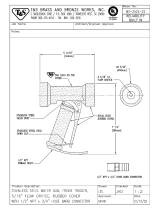
27. FI05060 Swivel adapter . . . . . . . . . . . . . . . . . . . . . . . . . . . . . . . . . . . . . . . . . . . . . . . . . . . . . . . . . .5
28. SE50280 Hydraulic Hose, Per Foot . . . . . . . . . . . . . . . . . . . . . . . . . . . . . . . . . . . . . . . . . . . . . . . . . .40
29. FI05061 Swivel Elbow. 90 Degrees . . . . . . . . . . . . . . . . . . . . . . . . . . . . . . . . . . . . . . . . . . . . . . . . .9
30. SE50094 Oil Filler . . . . . . . . . . . . . . . . . . . . . . . . . . . . . . . . . . . . . . . . . . . . . . . . . . . . . . . . . . . . . . . .1
31. KE51874 Pressure Relief Valve, Hydraulic . . . . . . . . . . . . . . . . . . . . . . . . . . . . . . . . . . . . . . . . . . . . .1
32. KE52382 Pressure Gauge . . . . . . . . . . . . . . . . . . . . . . . . . . . . . . . . . . . . . . . . . . . . . . . . . . . . . . . . .1
33. KE00860 Speed Control Cable Assembly . . . . . . . . . . . . . . . . . . . . . . . . . . . . . . . . . . . . . . . . . . . . .1
34. KE51622 Bridge Tilt Pin . . . . . . . . . . . . . . . . . . . . . . . . . . . . . . . . . . . . . . . . . . . . . . . . . . . . . . . . . . .1
35. FA95022 Retaining Ring . . . . . . . . . . . . . . . . . . . . . . . . . . . . . . . . . . . . . . . . . . . . . . . . . . . . . . . . . . .1
36. KE51623 Clevis Bracket . . . . . . . . . . . . . . . . . . . . . . . . . . . . . . . . . . . . . . . . . . . . . . . . . . . . . . . . . . .1
37. SE50353 Clevis Pin c/w Clips . . . . . . . . . . . . . . . . . . . . . . . . . . . . . . . . . . . . . . . . . . . . . . . . . . . . . .1
38. KE51624 Knuckle Joint . . . . . . . . . . . . . . . . . . . . . . . . . . . . . . . . . . . . . . . . . . . . . . . . . . . . . . . . . . . .1
39. KE50295 Mounting Bracket, Mercury Switch . . . . . . . . . . . . . . . . . . . . . . . . . . . . . . . . . . . . . . . . . . .1
40. KE50294 Mercury Switch . . . . . . . . . . . . . . . . . . . . . . . . . . . . . . . . . . . . . . . . . . . . . . . . . . . . . . . . .1-2
41. FA95055-3 Woodruff Key . . . . . . . . . . . . . . . . . . . . . . . . . . . . . . . . . . . . . . . . . . . . . . . . . . . . . . . . . . . .1
42. T40527 Housing, probe, 40 gal. . . . . . . . . . . . . . . . . . . . . . . . . . . . . . . . . . . . . . . . . . . . . . . . . . . .1
T40528 Housing, probe, 60 gal. . . . . . . . . . . . . . . . . . . . . . . . . . . . . . . . . . . . . . . . . . . . . . . . . . . .1
T40529 Housing, probe, 80 gal. . . . . . . . . . . . . . . . . . . . . . . . . . . . . . . . . . . . . . . . . . . . . . . . . . . .1
T40530 Housing, probe, 100 gal. . . . . . . . . . . . . . . . . . . . . . . . . . . . . . . . . . . . . . . . . . . . . . . . . . .1
T40531 Housing, probe, 125 gal. . . . . . . . . . . . . . . . . . . . . . . . . . . . . . . . . . . . . . . . . . . . . . . . . . .1
T40532 Housing, probe, 150 gal. . . . . . . . . . . . . . . . . . . . . . . . . . . . . . . . . . . . . . . . . . . . . . . . . . .1
T405321 Housing, probe, 200 gal. . . . . . . . . . . . . . . . . . . . . . . . . . . . . . . . . . . . . . . . . . . . . . . . . . .1
T405322 Housing, probe, 250 gal. . . . . . . . . . . . . . . . . . . . . . . . . . . . . . . . . . . . . . . . . . . . . . . . . . .1
43. KE51921 Pin, Scraper Arm . . . . . . . . . . . . . . . . . . . . . . . . . . . . . . . . . . . . . . . . . . . . . . . . . . . . . . . . .1
44. KE51925 Pin, Secondary Agitator . . . . . . . . . . . . . . . . . . . . . . . . . . . . . . . . . . . . . . . . . . . . . . . . . . .1
46. FA19506 Set Screw, Secondary Agitator . . . . . . . . . . . . . . . . . . . . . . . . . . . . . . . . . . . . . . . . . . . . .1
47. FA19507 Set Screw, Scraper Arm . . . . . . . . . . . . . . . . . . . . . . . . . . . . . . . . . . . . . . . . . . . . . . . . . . .1
48. KE00935 Secondary Agitator, 40 gal. (includes #44) . . . . . . . . . . . . . . . . . . . . . . . . . . . . . . . . . . . .1
KE00936 Secondary Agitator, 60 gal. (includes #44) . . . . . . . . . . . . . . . . . . . . . . . . . . . . . . . . . . . .1
KE00937 Secondary Agitator, 80 gal. (includes #44) . . . . . . . . . . . . . . . . . . . . . . . . . . . . . . . . . . . .1
KE00938 Secondary Agitator, 100 gal. (includes #44) . . . . . . . . . . . . . . . . . . . . . . . . . . . . . . . . . . .1
KE00939 Secondary Agitator, 125 gal. (includes #44) . . . . . . . . . . . . . . . . . . . . . . . . . . . . . . . . . . .1
KE00940 Secondary Agitator, 150 gal. (includes #44) . . . . . . . . . . . . . . . . . . . . . . . . . . . . . . . . . . .1
KE009401 Secondary Agitator, 200 gal. (includes #44) . . . . . . . . . . . . . . . . . . . . . . . . . . . . . . . . . . .1
KE009402 Secondary Agitator, 250 gal. (includes #44) . . . . . . . . . . . . . . . . . . . . . . . . . . . . . . . . . . .1
49. KE00947 Primary Agitator, 40 gal., with Gallon Markings (includes #16, 18 & 43) . . . . . . . . . . . . . .1
KE00948 Primary Agitator, 60 gal., with Gallon Markings (includes #16, 18 & 43) . . . . . . . . . . . . . .1
KE00949 Primary Agitator, 80 gal., with Gallon Markings (includes #16, 18 & 43) . . . . . . . . . . . . . .1
KE00950 Primary Agitator, 100 gal., with Gallon Markings (includes #16, 18 & 43) . . . . . . . . . . . . .1
KE00951 Primary Agitator, 125 gal., with Gallon Markings (includes #16, 18 & 43) . . . . . . . . . . . . .1
KE00952 Primary Agitator, 150 gal., with Gallon Markings (includes #16, 18 & 43) . . . . . . . . . . . . .1
KE009521 Primary Agitator, 200 gal., with Gallon Markings (includes #16, 18 & 43) . . . . . . . . . . . . .1
KE009522 Primary Agitator, 250 gal., with Gallon Markings (includes #16, 18 & 43) . . . . . . . . . . . . .1
KE00947-1 Primary Agitator, 40 gal., with Liter Markings (includes #16, 18 & 43) . . . . . . . . . . . . . . .1
KE00948-1 Primary Agitator, 60 gal., with Liter Markings (includes #16, 18 & 43) . . . . . . . . . . . . . . .1
KE00949-1 Primary Agitator, 80 gal., with Liter Markings (includes #16, 18 & 43) . . . . . . . . . . . . . . .1
KE00950-1 Primary Agitator, 100 gal., with Liter Markings (includes #16, 18 & 43) . . . . . . . . . . . . . .1
KE00951-1 Primary Agitator, 125 gal., with Liter Markings (includes #16, 18 & 43) . . . . . . . . . . . . . .1
KE00952-1 Primary Agitator, 150 gal., with Liter Markings (includes #16, 18 & 43) . . . . . . . . . . . . . .1
KE009521-1 Primary Agitator, 200 gal., with Liter Markings (includes #16, 18 & 43) . . . . . . . . . . . . . .1
KE009522-1 Primary Agitator, 250 gal., with Liter Markings (includes #16, 18 & 43) . . . . . . . . . . . . . .1
50. KE52687 Roller Bearing . . . . . . . . . . . . . . . . . . . . . . . . . . . . . . . . . . . . . . . . . . . . . . . . . . . . . . . . . . . 2
51. RT00505 Hydraulic Hose . . . . . . . . . . . . . . . . . . . . . . . . . . . . . . . . . . . . . . . . . . . . . . . . . . . . . .
specify length
52. KE00715 Bridge Swivel Housing Assembly . . . . . . . . . . . . . . . . . . . . . . . . . . . . . . . . . . . . . . . . . . . 1
GAS CONTROL ASSEMBLY
(for units built prior to March 2005)
GAS CONTROL ASSEMBLY
ITEM ON. PART NO. DESCRIPTION QTY.
1. KE53441 BLOWER, 115V, 60 HZ . . . . . . . . . . . . . . . . . . . . . . . . . . . . . . . . . . . . . . . . . . . . . . . . . . . . . . . . . . . . . . . . . . . .1
KE53441-1 BLOWER, 220V, 50 HZ . . . . . . . . . . . . . . . . . . . . . . . . . . . . . . . . . . . . . . . . . . . . . . . . . . . . . . . . . . . . . . . . . . . .1
2. KE54420 AIR INTAKE WASHER (NATURAL GAS) . . . . . . . . . . . . . . . . . . . . . . . . . . . . . . . . . . . . . . . . . . . . . . . . . . . . . . .1
KE54420-1 AIR INTAKE WASHER (PROPANE) . . . . . . . . . . . . . . . . . . . . . . . . . . . . . . . . . . . . . . . . . . . . . . . . . . . . . . . . . . .1
3. KE54239 CAPACITOR . . . . . . . . . . . . . . . . . . . . . . . . . . . . . . . . . . . . . . . . . . . . . . . . . . . . . . . . . . . . . . . . . . . . . . . . . . . . .1
4. KE01426-4 MIXING CHAMBER, 40 GALLON KETTLES . . . . . . . . . . . . . . . . . . . . . . . . . . . . . . . . . . . . . . . . . . . . . . . . . . . .1
KE01426-1 MIXING CHAMBER, 60 GALLON KETTLES . . . . . . . . . . . . . . . . . . . . . . . . . . . . . . . . . . . . . . . . . . . . . . . . . . . .1
KE01426-2 MIXING CHAMBER, 80 GALLON KETTLES . . . . . . . . . . . . . . . . . . . . . . . . . . . . . . . . . . . . . . . . . . . . . . . . . . . .1
KE01426-3 MIXING CHAMBER, 100 GALLON KETTLES . . . . . . . . . . . . . . . . . . . . . . . . . . . . . . . . . . . . . . . . . . . . . . . . . . .1
5. KE53582 TUBING 1/4 INCH SILICONE . . . . . . . . . . . . . . . . . . . . . . . . . . . . . . . . . . . . . . . . . . . . . . . . . . . . . . . . . . . . . . .1
FI05156 HOSE FITTING . . . . . . . . . . . . . . . . . . . . . . . . . . . . . . . . . . . . . . . . . . . . . . . . . . . . . . . . . . . . . . . . . . . . . . . . . . .1
6. KE53402 AIR ORIFICE, 40 GALLON KETTLES . . . . . . . . . . . . . . . . . . . . . . . . . . . . . . . . . . . . . . . . . . . . . . . . . . . . . . . . .1
KE53402-1 AIR ORIFICE, 60 - 100 GALLON KETTLES . . . . . . . . . . . . . . . . . . . . . . . . . . . . . . . . . . . . . . . . . . . . . . . . . . . . .1
KE53402-2 AIR ORIFICE, 40 GALLON KETTLES (50 HZ BLOWER) . . . . . . . . . . . . . . . . . . . . . . . . . . . . . . . . . . . . . . . . . . .1
KE53402-3 AIR ORIFICE, 60 - 100 GALLON KETTLES (50 HZ BLOWER ) . . . . . . . . . . . . . . . . . . . . . . . . . . . . . . . . . . . . . .1
7. KE01449 BLOWER MOUNTING PIPE ASSEMBLY . . . . . . . . . . . . . . . . . . . . . . . . . . . . . . . . . . . . . . . . . . . . . . . . . . . . . . .1
8. KE53618 SIGHT GLASS GASKET . . . . . . . . . . . . . . . . . . . . . . . . . . . . . . . . . . . . . . . . . . . . . . . . . . . . . . . . . . . . . . . . . . . .1
9. KE53617 SIGHT GLASS . . . . . . . . . . . . . . . . . . . . . . . . . . . . . . . . . . . . . . . . . . . . . . . . . . . . . . . . . . . . . . . . . . . . . . . . . . .1
10. KE53619 SIGHT GLASS RETAINER . . . . . . . . . . . . . . . . . . . . . . . . . . . . . . . . . . . . . . . . . . . . . . . . . . . . . . . . . . . . . . . . . .1
11. KE00515 THERMISTOR . . . . . . . . . . . . . . . . . . . . . . . . . . . . . . . . . . . . . . . . . . . . . . . . . . . . . . . . . . . . . . . . . . . . . . . . . . . .1
12. KE50556-2 WATER LEVEL PROBE . . . . . . . . . . . . . . . . . . . . . . . . . . . . . . . . . . . . . . . . . . . . . . . . . . . . . . . . . . . . . . . . . . . . .1
13. KE53437-3 IGNITOR . . . . . . . . . . . . . . . . . . . . . . . . . . . . . . . . . . . . . . . . . . . . . . . . . . . . . . . . . . . . . . . . . . . . . . . . . . . . . . . .1
14. KE53570 GASKET FOR IGNITOR . . . . . . . . . . . . . . . . . . . . . . . . . . . . . . . . . . . . . . . . . . . . . . . . . . . . . . . . . . . . . . . . . . . .1
15. FI05257 SHUT-OFF COCK . . . . . . . . . . . . . . . . . . . . . . . . . . . . . . . . . . . . . . . . . . . . . . . . . . . . . . . . . . . . . . . . . . . . . . . . .1
16. FI05213 PLUG . . . . . . . . . . . . . . . . . . . . . . . . . . . . . . . . . . . . . . . . . . . . . . . . . . . . . . . . . . . . . . . . . . . . . . . . . . . . . . . . . .1
17. KE53422 SPRING . . . . . . . . . . . . . . . . . . . . . . . . . . . . . . . . . . . . . . . . . . . . . . . . . . . . . . . . . . . . . . . . . . . . . . . . . . . . . . . .1
18. FA05002-4 “O” RING . . . . . . . . . . . . . . . . . . . . . . . . . . . . . . . . . . . . . . . . . . . . . . . . . . . . . . . . . . . . . . . . . . . . . . . . . . . . . . .1
19. GAS ORIFICES:
KE53403-8 NATURAL GAS - SEA LEVEL UP TO 2000', 40 GALLON KETTLES . . . . . . . . . . . . . . . . . . . . . . . . . . . . . . . . . .1
KE53403-5 PROPANE GAS - SEA LEVEL UP TO 2000', 40 GALLON KETTLES . . . . . . . . . . . . . . . . . . . . . . . . . . . . . . . . . .1
KE53403-6 NATURAL GAS - SEA LEVEL UP TO 2000', 60 - 100 GALLON KETTLES . . . . . . . . . . . . . . . . . . . . . . . . . . . . .1
KE53403-7 PROPANE GAS - SEA LEVEL UP TO 2000', 60 - 100 GALLON KETTLES . . . . . . . . . . . . . . . . . . . . . . . . . . . . .1
KE53403-8 NATURAL GAS - 2000' UP TO 4000', 40 GALLON KETTLES . . . . . . . . . . . . . . . . . . . . . . . . . . . . . . . . . . . . . . .1
KE53403-9 PROPANE GAS - 2000' UP TO 4000', 40 GALLON KETTLES . . . . . . . . . . . . . . . . . . . . . . . . . . . . . . . . . . . . . .1
KE53403-10 NATURAL GAS - 2000' UP TO 4000', 60 - 100 GALLON KETTLES . . . . . . . . . . . . . . . . . . . . . . . . . . . . . . . . . .1
KE53403-11 PROPANE GAS - 2000' TO 4000', 60 - 100 GALLON KETTLES . . . . . . . . . . . . . . . . . . . . . . . . . . . . . . . . . . . . .1
KE53403-12 NATURAL GAS - 4000' UP TO 6000', 40 GALLON KETTLES . . . . . . . . . . . . . . . . . . . . . . . . . . . . . . . . . . . . . . .1
KE53403-13 PROPANE GAS - 4000' UP TO 6000', 40 GALLON KETTLES . . . . . . . . . . . . . . . . . . . . . . . . . . . . . . . . . . . . . .1
KE53403-10 NATURAL GAS - 4000' UP TO 6000', 60 - 100 GALLON KETTLES . . . . . . . . . . . . . . . . . . . . . . . . . . . . . . . . . .1
KE53403-14 PROPANE GAS - 4000' UP TO 6000', 60 - 100 GALLON KETTLES . . . . . . . . . . . . . . . . . . . . . . . . . . . . . . . . . .1
20. FA05002-29 “O” RING . . . . . . . . . . . . . . . . . . . . . . . . . . . . . . . . . . . . . . . . . . . . . . . . . . . . . . . . . . . . . . . . . . . . . . . . . . . . . . .1
21. FI05226-4 NIPPLE, 1/2" NPT, 5 5/16" LONG . . . . . . . . . . . . . . . . . . . . . . . . . . . . . . . . . . . . . . . . . . . . . . . . . . . . . . . . . . . . .1
22. FI00073 UNION, 1/2" . . . . . . . . . . . . . . . . . . . . . . . . . . . . . . . . . . . . . . . . . . . . . . . . . . . . . . . . . . . . . . . . . . . . . . . . . . . . .1
23. FI00133 ELBOW, 1/2", STREET . . . . . . . . . . . . . . . . . . . . . . . . . . . . . . . . . . . . . . . . . . . . . . . . . . . . . . . . . . . . . . . . . . . . .1
24. KE93909 STRIP, TO HOLD BLOWER DOWN . . . . . . . . . . . . . . . . . . . . . . . . . . . . . . . . . . . . . . . . . . . . . . . . . . . . . . . . . . .1
25. FI00040-1 ELBOW, 1/2" . . . . . . . . . . . . . . . . . . . . . . . . . . . . . . . . . . . . . . . . . . . . . . . . . . . . . . . . . . . . . . . . . . . . . . . . . . . . .1
26. FI00579 NIPPLE, 1/2" NPT, 4" LONG, KGL-60-T . . . . . . . . . . . . . . . . . . . . . . . . . . . . . . . . . . . . . . . . . . . . . . . . . . . . . . . .1
FI05226-2 NIPPLE, 1/2" NPT, 4" LONG, KGL-80-T . . . . . . . . . . . . . . . . . . . . . . . . . . . . . . . . . . . . . . . . . . . . . . . . . . . . . . . .1
27. KE55004-3 RETAINING PLATE . . . . . . . . . . . . . . . . . . . . . . . . . . . . . . . . . . . . . . . . . . . . . . . . . . . . . . . . . . . . . . . . . . . . . . . .1
28. FI00573 NIPPLE, 1/2" NPT, 1 1/8" LONG . . . . . . . . . . . . . . . . . . . . . . . . . . . . . . . . . . . . . . . . . . . . . . . . . . . . . . . . . . . . . .1
29. FI05231 BUSHING, 3/4 - 1/2" NPT FLUSH, BLACK IRON . . . . . . . . . . . . . . . . . . . . . . . . . . . . . . . . . . . . . . . . . . . . . . . .1
30. F01518-1 GAS SHUT-OFF VALVE, 3/4" (NOT FOR FRENCH CE KETTLES) . . . . . . . . . . . . . . . . . . . . . . . . . . . . . . . . . . . .1
31. FI05226 NIPPLE, 1/2" NPT, 8" LONG . . . . . . . . . . . . . . . . . . . . . . . . . . . . . . . . . . . . . . . . . . . . . . . . . . . . . . . . . . . . . . . . .1
32. FI05222 SWIVEL ELBOW . . . . . . . . . . . . . . . . . . . . . . . . . . . . . . . . . . . . . . . . . . . . . . . . . . . . . . . . . . . . . . . . . . . . . . . . . .1
33. FI05223 SPECIAL NIPPLE . . . . . . . . . . . . . . . . . . . . . . . . . . . . . . . . . . . . . . . . . . . . . . . . . . . . . . . . . . . . . . . . . . . . . . . . .1
34. KE02053 GAS VALVE ASSEMBLY . . . . . . . . . . . . . . . . . . . . . . . . . . . . . . . . . . . . . . . . . . . . . . . . . . . . . . . . . . . . . . . . . . . .1
35. KE53390 BRACKET FOR GAS VALVE . . . . . . . . . . . . . . . . . . . . . . . . . . . . . . . . . . . . . . . . . . . . . . . . . . . . . . . . . . . . . . . . .1
36. FI00607 NIPPLE, 3/4" NPT, 1 1/2" LONG . . . . . . . . . . . . . . . . . . . . . . . . . . . . . . . . . . . . . . . . . . . . . . . . . . . . . . . . . . . . . .1
37. KE01500-5 BURNER, 40 GALLON KETTLES, 140,000 BTU . . . . . . . . . . . . . . . . . . . . . . . . . . . . . . . . . . . . . . . . . . . . . . . . .1
KE01500-1 BURNER, 60-100 GALLON KETTLES, 190,000 BTU . . . . . . . . . . . . . . . . . . . . . . . . . . . . . . . . . . . . . . . . . . . . .1
38. KE53397 GASKET, BURNER . . . . . . . . . . . . . . . . . . . . . . . . . . . . . . . . . . . . . . . . . . . . . . . . . . . . . . . . . . . . . . . . . . . . . . . .1
39. FI05231 ADAPTOR . . . . . . . . . . . . . . . . . . . . . . . . . . . . . . . . . . . . . . . . . . . . . . . . . . . . . . . . . . . . . . . . . . . . . . . . . . . . . .1
40. KE601085 COVER FOR GAS VALVE . . . . . . . . . . . . . . . . . . . . . . . . . . . . . . . . . . . . . . . . . . . . . . . . . . . . . . . . . . . . . . . . . . .1
41. RB018151 GASKET FOR COVER . . . . . . . . . . . . . . . . . . . . . . . . . . . . . . . . . . . . . . . . . . . . . . . . . . . . . . . . . . . . . . . . . . . . .1
42. KE601081 BRACKET . . . . . . . . . . . . . . . . . . . . . . . . . . . . . . . . . . . . . . . . . . . . . . . . . . . . . . . . . . . . . . . . . . . . . . . . . . . . . . .1
GAS CONTROL ASSEMBLY
(for units built after February 2005)
1
2
3
4
5
6
9
10
8
7
Tilting
Models
1. FI00040-1 ELBOW, 1/2" . . . . . . . . . . . . . . . . . . . . . . . . . . . . . . . . . . . . . . . . . . . . . . . . . . . . . . . . . . . . . . . . .1
2. FI05226 NIPPLE, 1/2" NPT, 8" LONG . . . . . . . . . . . . . . . . . . . . . . . . . . . . . . . . . . . . . . . . . . . . . . . . . . . . .1
3. FI05231 ADAPTOR . . . . . . . . . . . . . . . . . . . . . . . . . . . . . . . . . . . . . . . . . . . . . . . . . . . . . . . . . . . . . . . . . . .1
4. FI05222 SWIVEL ELBOW . . . . . . . . . . . . . . . . . . . . . . . . . . . . . . . . . . . . . . . . . . . . . . . . . . . . . . . . . . . . . .1
5. FI05223 SPECIAL NIPPLE . . . . . . . . . . . . . . . . . . . . . . . . . . . . . . . . . . . . . . . . . . . . . . . . . . . . . . . . . . . . .1
6. KE55240R GAS VALVE . . . . . . . . . . . . . . . . . . . . . . . . . . . . . . . . . . . . . . . . . . . . . . . . . . . . . . . . . . . . . . . . . .1
7. F015 GAS SHUT-OFF VALVE, 3/4" . . . . . . . . . . . . . . . . . . . . . . . . . . . . . . . . . . . . . . . . . . . . . . . . . . . . .1
8. KE000960 NIPPLE PLATE WELDMENT . . . . . . . . . . . . . . . . . . . . . . . . . . . . . . . . . . . . . . . . . . . . . . . . . . . . .1
9. FA30505-1 WASHER, 1/4” . . . . . . . . . . . . . . . . . . . . . . . . . . . . . . . . . . . . . . . . . . . . . . . . . . . . . . . . . . . . . . .4
10. FA11256 HEX BOLT, 1/4-20 X 1/2, 18-8 SS . . . . . . . . . . . . . . . . . . . . . . . . . . . . . . . . . . . . . . . . . . . . . . . . .4
GEARBOX ASSEMBLY
40
41
42
26 27 28
39
4
5
6
5
7
5
6
5
4
8
25
15
14
1
10
2
3
9
11
12
13
16 19 20
21
22
32
30
32
31
24
23
24
23
36
34
33
35
37
38
  • Page 1 1
  • Page 2 2
  • Page 3 3
  • Page 4 4
  • Page 5 5
  • Page 6 6
  • Page 7 7
  • Page 8 8
  • Page 9 9
  • Page 10 10
  • Page 11 11
  • Page 12 12
  • Page 13 13
  • Page 14 14
  • Page 15 15
  • Page 16 16
  • Page 17 17
  • Page 18 18
  • Page 19 19
  • Page 20 20
  • Page 21 21
  • Page 22 22
  • Page 23 23
  • Page 24 24
  • Page 25 25
  • Page 26 26
  • Page 27 27
  • Page 28 28
  • Page 29 29
  • Page 30 30
  • Page 31 31
  • Page 32 32
  • Page 33 33
  • Page 34 34
  • Page 35 35
  • Page 36 36
  • Page 37 37
  • Page 38 38
  • Page 39 39
  • Page 40 40
  • Page 41 41
  • Page 42 42
  • Page 43 43
  • Page 44 44
  • Page 45 45
  • Page 46 46
  • Page 47 47
  • Page 48 48
  • Page 49 49
  • Page 50 50
  • Page 51 51
  • Page 52 52
  • Page 53 53
  • Page 54 54
  • Page 55 55
  • Page 56 56

Cleveland MKGL-100-T User manual

Category
Electric kettles
Type
User manual

Ask a question and I''ll find the answer in the document

Finding information in a document is now easier with AI