
Form RZ-NA I-V3-VL (6-16), P/N 197108R4, page 1
Installation Form for Vertical Louvers,
Option CD1
Applies to:
Models UDAP, UDAS, UDBP, UDBS, UEAS
Vertical louvers are designed to direct the discharge air to provide a wider throw
pattern. These vertical louver option packages apply to unit heater Models UDAP,
UDAS, UDBP, UDBS, and UEAS as listed in the table below.
Description and
Application
Installation
Instructions
WARNING: Improper installation, adjustment, alteration,
service, or maintenance can cause property damage, injury
or death. Read the installation, operation, and maintenance
instructions thoroughly before installing or servicing this
equipment.
Installation should be done by a qualied agency in accordance with these
instructions and in compliance with all codes and requirements of authorities
having jurisdiction.
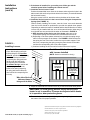
1. Assemble the Vertical Louver Frame (See FIGURE 1.)
Using the screws in the kit, attach both sides to the top. (NOTE: Top and bottom
are identical.) Attach the assembly to the bottom creating a frame.
FIGURE 1 - Assemble
the Louver Frame
Components
Assemble
louver frame
with screws.
Louver Frame Side
(parts are identical)
Louver Frame
Top or Bottom
(parts are identical)
Form I-V3-VL (6-16)
Obsoletes Form I-V3-VL (Version A.1)
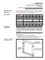
Models UDAS, UDAP,
UDBP, UDBS
30, 45 60, 75 100, 125
150, 175,
200
225, 250
300, 350,
400
Model UEAS 130, 180 260, 310
Option Pkg P/N 197097 197098 197099 201199 201200 201201
Components - (qty) and P/N
Louver Frame Top and
Bottom
(2)197056 (2)197189 (2)197190
Louver Frame Sides (2)197057 (2)197058 (2)197059 (2)197186 (2)197187 (2)197188
Screws
(20) 195638, #8-18 x 3/8" long, AB point, slotted indented serrated hex
washer head
Louvers (5)196232 (5)196231 (5)196233 (8)196572 (8)196573 (8)195315
Compression Springs (5)195046 (5)195046 (5)195046 (8)195046 (8)195046 (8)195046

Form RZ-NA I-V3-VL (6-16), PN 197108R4, page 2
Installation
Instructions
(cont’d)
2. If the heater is installed, for your safety, turn off the gas and the
electrical power before installing the vertical louvers.
3. Install the Vertical Louver Frame
Position the assembled louver frame in the heater outlet so that the holes in the
tabs on each side are lined up with the holes in the heater. (The tabs t between
the horizontal louvers.)
Using the screws in the kit, attach the tabs to the sides of the heater outlet.
4. Install the Vertical Louvers in the Louver Frame Using the Compression
Springs (See FIGURE 2.)
Before actually installing the louvers, note the louver curve and determine
how the louvers should be positioned to provide the optimal throw pattern.
Depending on where the heater is installed and the desired direction of airow,
louvers may be installed with the curve all the same direction (either way) or
the right half one way and the left the other as illustrated in FIGURE 2.
a) With the wider section facing out of the heater, place one of the
compression springs over the tab on the notched end of the louver.
b) Depending on the throw pattern selected, the end with the spring can go
either in the top support or the bottom. See FIGURE 2. Slide the tab with
the spring into one of the holes in either the top or bottom support. Push
the louver, compressing the spring enough to place the tab on the other
end into the corresponding hole in the other support.
c) Continue installing the louvers until all vertical louvers are in place.
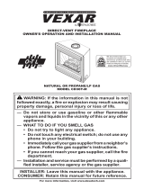
FIGURE 2 -
Installing Louvers
5. Adjust the horizontal and vertical louvers to provide the desired throw pattern.
CAUTION: To avoid getting burned, adjust louvers while
heater is not in operation. If louvers are adjusted while heater
is in operation, wear protective gloves.
6. Turn on the electric and the gas. Light by following the lighting instructions on
the heater. Check for proper operation.
1) On the notched end of the
louver, slide the spring over the tab.
2) When facing the unit,
for airflow
to the left, push the tab with the spring
into a hole in the top louver frame
(compressing the spring) and insert
the tab on the other end into the
corresponding hole in the bottom.
For airflow to the right, push the tab
with the spring into a hole in the
bottom louver frame (compressing
the spring) and insert the tab on the
other end into the corresponding hole
in the top.
Wider side of the louver
blade must always be
facing out of the heater.
Front View of Vertical Louver Frame
with Louvers Installed
(NOTE: Heater is removed for clarity.)
Specications & illustrations subject to change without notice and without incurring obligations.
© Nortek Global HVAC, LLC 2016. All rights reserved.
All marks are the property of their respective organizations.
O’Fallon, MO I Printed in U.S.A. (6/16)
Form I-V3-VL (6-16), P/N 197108 R4
-
 1
1
-
 2
2


Reznor UDBP Installation guide
- Type
- Installation guide
Ask a question and I''ll find the answer in the document
Finding information in a document is now easier with AI
Related papers
-
Reznor RV Installation guide
-
Reznor UDBP User manual
-
-
Reznor SHH Installation guide
-
-
Reznor LDAP Installation guide
-
Reznor UEAS Installation guide
-
-
Reznor UDAS Installation & Operation Manual
-
Other documents
-
Thomas & Betts UDAS User manual
-
Mammoth APD Installation guide
-
Unbranded APD Installation guide
-
-
-
 Vexar CD36T-M Owner's manual
-
 Vexar CD36TN-M User manual
-
Desa (V)T32EN-A Series, (V)T32EP-A Series User manual
-
Desa (V)CB36N(E) User manual
-
FMI CB36N User manual

