Page is loading ...

11
WARNING
RISK OF PERSONAL INJURY,
DEATH, OR PROPERTY DAMAGE.
This conversion kit shall be installed by a
qualified service agency in accordance with
the manufacturer’s instructions and all appli-
cable codes and requirements of the author-
ity having jurisdiction. If the information in
these instruction is not followed exactly, a
fire or explosion or production of carbon
monoxide may result, causing property
damage, personal injury, or loss of life. The
qualified service agency is responsible for the
proper installation of this kit. The installation
is not proper and complete until the opera-
tion of the converted appliance is checked as
specified in the manufacturer’s instructions
supplied with the kit.The qualified service
agency performing this installation assumes
responsibility for this conversion.
AVERTISSEMENT
RISQUE DE BLESSURE, MORT OU
DOMMAGE À LA PROPRIÉTÉ
Cette trousse de conversion doit être
installée par un technicien agréé, selon les
instructions du fabricant et selon toutes
les exigences et tous les codes pertinents
de l’autorité compétente. Assurez-vous
de bien suivre les instructions dans cette
notice pour réduire au minimum le risque
d’incendie, d’explosion ou la production de
monoxyde de carbone pouvant causer des
dommages matériels, des blessures ou la
mort. Le tecnicien agréé est responsable de
l’installation de cette trousse. L’installation
n’est pas adéquate ni complète tant que le
bon fonctionnement de l’appareil converti
n’a pas été vérifié selon les instructions
du fabricant fournies avec la trousse. Le
fournisseur de service qualifié ayant réalisé
l'installation assume les responsabilités liées
à la conversion.
INSTALLATION INSTRUCTIONS FOR GAS CONVERSION KITS FOR USE WITH
MONTEBELLO-B™ SEE-THROUGH DIRECT VENT GAS FIREPLACES WITH SIT PROFLAME SYSTEMS
[FIREPLACE MODELS DRT63STTEN/EP/YN AND MONTEBELLOSTTEN/EP/YN]
P/N 901142-00
Rev. A 03/2021
HEARTH PRODUCTS
KITS AND ACCESSORIES
GAS CONVERSION KIT
MONTEBELLO-B™ SEE-THROUGH / SIT PROFLAME
Gas Conversion Kits
Description Model No. Cat.
No.
Nat. Gas to Propane GCK-E-MONT-B-NP F4698
Propane to Nat. Gas GCK-E-MONT-B-PN F4699
Note:
• Before installing gas components, apply pipe
joint compound or Teflon tape to all pipe
fittings. Always use propane-resistant joint
compounds. Never use pipe joint compounds
on flare fittings.
• The burner orifice provided in this kit is only
for use at elevations of 0–4,500 ft (0–1372
m) in the U.S.A. and Canada. At higher eleva-
tions, the BTU input must be derated by 4%
for every 1,000 ft (305 m) to maintain the
proper ratio of gas to air.
If the installer must convert the unit to adjust
for varying altitudes, a deration information
sticker must be completed by the installer
and attached to the appliance at time of con-
version. Contact your local gas supplier for
deration requirements for your area.
In Canada:
• The conversion shall be carried out in ac-
cordance with the requirements of the pro-
vincial authorities having jurisdiction and in
accordance with the requirements of the CAN/
CSA-B149.1 Installation code.
Au Canada:
• La conversion devra être effectuée
conformément aux recommandations
des autorités provinciales ayant juridic-
tion et conformément aux exigences du
code d'installation CAN/CSA-B149.1.
GENERAL INFORMATION
Gas conversion kits adapt the appliance from
the use of one type of gas to another. This kit
contains all components required to complete
the conversion, as well as a self-adhesive label
with gas conversion information to apply to the
appliance rating plate.
DRAFT
10/30/2017
DRAFT
10/30/2017
KIT CONTENTS
(1) ea. Brass Burner Orifice
(1) ea. Pilot Orifice
(1) ea. SIT Regulator Conversion Kit
(1) ea. Gas Conversion Information Label
(1) ea. Burner Assembly
REQUIRED TOOLS
• 5/32" Allen Wrench
• Torx Bit (T20 with 1/4" shank and center
hole) or Flat Blade Screwdriver
• 1/2" Open-End Wrench
CAUTION
RISK OF PERSONAL INJURY OR PROPERTY DAMAGE.
• Never operate fireplace with glass door assemblies removed.
• Securely tighten door latch screws when reinstalling glass door assemblies to prevent doors
from falling out.
• Handle glass door assemblies with extreme care. Replace damaged glass door assemblies
with approved replacement assemblies only.
The door assemblies contain ceramic glass. Handle with care to prevent damage. If the door frame
or glass becomes damaged, replace the entire glass door assembly with a manufacturer-approved
replacement assembly only. Do not attempt to substitute any materials used on door assemblies
or replace cracked or broken glass with any other materials.
WARNING
HOT GLASS WILL CAUSE BURNS. DO NOT TOUCH GLASS UNTIL COOLED.
NEVER ALLOW CHILDREN TO TOUCH GLASS.
• Fireplaces surfaces get EXTREMELY HOT!
• Install only when fireplace is OFF and COLD.
• The glass on the front of the fireplace reaches EXTREMELY HIGH temperatures and can cause
severe burns if touched. Even after the gas is turned off, fireplace surfaces remain extremely hot.
• Keep children away from an operating fireplace. Closely supervise children in any room where
a fireplace is operating to prevent contact with glass.

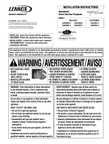
Figure 2: SIT Proflame Valve
2
NOTE: DIAGRAMS & ILLUSTRATIONS ARE NOT TO SCALE.
WARNING / AVERTISSEMENT
BURN HAZARD. Install only when
fireplace is OFF and COLD.
RISQUE DE BRÛLURE. Installer
seulement lorsque le foyer est ÉTEINT
et FROID.
INSTALLATION INSTRUCTIONS
Step 1. Shut OFF the gas supply to the appli-
ance FIRST; then disconnect the power
supply at the circuit breaker.
Ensure appliance is COLD before starting
installation.
Step 2. Remove the front glass door/frame (on
the valve access side).
Step 3. Carefully remove the logs. See the fire-
place Installation Instructions and Care and
Operation Manual for detailed log removal
and placement information.
Note: Logs are FRAGILE! Handle with care
to prevent breakage.
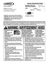
Step 4. See Figure 1. Follow these steps to
remove the burner assembly with attached
air shutter assembly:
a. Remove the 5/16" screws securing the
burner to the firebox.
b. Remove the 5/16" screws securing the
pilot bracket to the burner assembly.
c. Slide the burner back and up to allow the
air shutter to clear the pilot bracket.
d. Discard burner assembly.
Figure 3
Pilot
Orifice
Pilot
Hood
NOTICE
• Read all steps before starting installation.
• These instructions must be left with the
appliance.
• All warnings, precautions, and instructions
in the Installation Instructions and Care
and Operation Manual (IICO) provided
with the appliance also apply to these
instructions.
• If you encounter any problems, need
clarification of these instructions, or are
not qualified to properly install this kit,
contact your local distributor or dealer.
Step 5. Refer to Figure 2 and the instructions
provided with the SIT Regulator Conversion
Kit. Using a Torx T20 (with 1/4" shank and
center hole) or slotted screwdriver, remove
and discard the two pressure regulator
mounting screws, the pressure regulator
tower, the diaphragm assembly (if appli-
cable) (“A” in Figure 2) and the spring
(“B” in Figure 2). Discard all removed
components.
Ensure the rubber gasket installed on the
back of the replacement pressure regulator
(“C” in Figure 2) is properly positioned.
Step 6. Install the new stepper motor pres-
sure regulator assembly using the supplied
screws as shown in Figure 2. Tighten screws
securely (reference torque = 25 lb-in).
Step 7. Install the enclosed identification label
to the valve body where it can be easily seen.
Step 8. Make stepper motor and valve electri-
cal connections.
Step 9. Follow these steps to replace the pilot
orifice (see Figure 3):
a. Remove the pilot hood assembly to
access the hexed pilot orifice.
b. Using a 5/32" allen wrench, remove and
replace the orifice with the one provided
with the kit.
NOTE: Use extreme care to avoid damaging
the igniter assembly.
Step 10. Refer to Figures 1 and 4.
Remove the orifice from the manifold and re-
place it with the provided orifice.
Verify that the orifice is the correct size. See
Table 1 for orifice size and Figure 4 for an
illustration of the orifice.
Use pipe joint compound or Teflon tape when
installing the orifice.
Figure 4
size
CAUTION / ATTENTION
Before proceeding with this conversion,
the gas supply must be shut off prior to
disconnecting the electrical power.
Avant de procéder à cette conversion,
l’approvisionnement en gaz doit être
coupée avant de débrancher l’ali men-
ta tion électrique.
Burner Orifice Sizes
Elevation 0–4500 ft ( 0–1372 m)
Fireplace
Model NATURAL GAS
drill size (inches)
PROPANE
drill size (inches)
TEN/P Models #25 (0.150")
Cat. No. F4700
#47 (0.0785")
Cat. No. F4714
Table 1
Gas Valve Assembly
Burner Orifice
Figure 1 - NOTE : NG Burner Assembly is
shown.
Burner Assembly
INNOVATIVE HEARTH PRODUCTS • MONTEBELLO-B™ SEE-THROUGH GAS FIREPLACES WITH SIT PROFLAME • GAS CONVERSION KIT INSTALLATION INSTRUCTIONS
Pressure Regulator Mounting
Screws (Torx-T20)
Connect GTMS wire harness.
(A) Remove diaphragm.
(B) Remove spring.
(C) Install new rubber gasket on
pressure regulator tower.
Pressure Regulator
Tower
Line (IN)
Test Port
Manifold
(OUT)
Test Port

NOTE: DIAGRAMS & ILLUSTRATIONS ARE NOT TO SCALE.
3
INNOVATIVE HEARTH PRODUCTS • MONTEBELLO-B™ SEE-THROUGH GAS FIREPLACES WITH SIT PROFLAME • GAS CONVERSION KIT INSTALLATION INSTRUCTIONS
Inputs
Model No. Input (BTU/Hr)
NATURAL GAS
TEN, TYN Models 57,000 to 37,000
PROPANE
TEP Models 50,000 to 40,000
Table 4
Inlet Gas Supply Pressure (All Models)
Fuel # Minimum Maximum
TEN, TYN
MODELS 5.0" WC
(1.24 kPa)
10.5" WC
(2.61 kPa)
TEP
MODELS 11.0" WC
(2.74 kPa)
13.0" WC
(3.23 kPa)
Table 2
Figure 6: Pilot Flame Appearance
Pilot Hood
Igniter Rod
Flame
Sensor Pilot
Nozzles
Step 11. Follow these steps to replace the
burner and reassemble the remaining
components:
a) Set the burner assembly provided with
this kit in position.
b) Slide the air shutter venturi over the
orifice (see Figures 1 and 5).
c) Reattach pilot bracket to burner.
d) Replace the screws securing the burner
to the firebox.
Use pipe joint compound or Teflon tape on
all pipe fittings before installing (ensure
propane resistant compounds are used in
propane applications, do not use pipe joint
compounds on flare fittings).
Step 12. Attach the provided Conversion
Information Label to the rating plate on the
appliance.
Step 13. Carefully replace the logs. See the
fireplace Installation Instructions and Care
and Operation Manual for detailed log place-
ment information.
Note: Logs are FRAGILE! Handle with
care to prevent breakage.
Step 14. Apply gas to the system, and relight
the appliance. With the main burner “ON,”
test the new pressure regulator assembly
and all gas line joints for leaks using a gas
leak test solution.
Step 15. Relight the main burner and verify
proper burner ignition and operation.
Inspect the pilot system for proper flame.
The pilot flame should engulf the flame
sensor, as shown in Figure 6.
• For complete lighting instructions, see the
lighting label in the appliance control com-
partment or in the Installation Instructions
and Care and Operation Manual provided
with the appliance.
Step 16. Using a manometer, test the inlet and
manifold gas pressures.
• For test port locations, see Figure 2.
• For gas supply pressure requirements, see
Tables 2 and 3.
NOTICE: ALWAYS TEST PRESSURES WITH
THE VALVE REGULATOR CONTROL
AT THE HIGHEST SETTING.
Continue with Step 17 (on the next page)
for instructions on burner/shutter adjust-
ment and proper flame appearance.
Manifold Gas Supply Pressure (All Models)
Fuel # Low High
TEN, TYN
MODELS (Lo) 1.6" WC
(0.4 kPa)
(Hi) 3.5" WC
(0.87 kPa)
TEP
MODELS (Lo) 6.3" WC
(1.57 kPa)
(Hi) 10.0" WC
(2.49 kPa)
Table 3
Gas Supply Pressure Requirements
Tables 2 and 3 list the appliances inlet and
manifold gas supply pressure requirements.
BTU Inputs
BTU inputs for these appliances are listed in
Table 1.
Burner Orifice
Air Shutter Adjustment Arm
Flex Line
Figure 5 - NOTE : NG Burner Assembly is shown.
LP
NG

4
NOTE: DIAGRAMS & ILLUSTRATIONS ARE NOT TO SCALE.
Figure 7
NOTE: When converting and using fireplace
with LP gas, the shutter gap should be 90-
100% OPEN.
• If the flame appears weak or sooty (as
described at right), adjust the air shutter
until proper flame appearance is achieved.
• If flame stays lowered blue, incrementally
adjust the air shutter to a more CLOSED
position until proper flame appearance is
achieved.
INNOVATIVE HEARTH PRODUCTS • MONTEBELLO-B™ SEE-THROUGH GAS FIREPLACES WITH SIT PROFLAME • GAS CONVERSION KIT INSTALLATION INSTRUCTIONS
NOTE: DIAGRAMS & ILLUSTRATIONS ARE NOT TO SCALE.
Flame Appearance and Sooting
Proper flame appearance is a flame that is blue
at the base and becomes yellowish-orange in
the body of the flame. When the appliance is
first lit, the entire flame may be blue and will
gradually turn yellowish-orange during the first
30 minutes of operation. After 30 minutes of
operation, if the flame is blue, or if the flame is
orange with evidence of sooting (black tip), the
air shutter opening may need to be adjusted.
If the air shutter opening is closed too far,
sooting may develop. Sooting is indicated by
black puffs developing at the tips of very long
orange flames. Sooting results in black deposits
forming on the logs, appliance inside surfaces
and on exterior surfaces adjacent to the vent
termination.
Sooting is caused by incomplete combustion
in the flames and lack of combustion air enter-
ing the air shutter opening. To achieve a warm
yellowish-orange flame with an orange body
that does not soot, the shutter opening must be
adjusted between these two extremes.
Air Shutter Adjustment Guidelines
Amount of
Primary Air
Flame
Color
Air Shutter
Adjustment
If air shutter is
closed too far Flame will
be orange Air shutter
gap should be
increased
If air shutter is
open too far Flame will
be blue Air shutter
gap should be
decreased
Step 17. Read "Flame Appearance and
Sooting" and "Air Shutter Adjustment
Guidelines" (at right) before proceeding.
For complete details, see the
Installation
Instructions and Care and Operation
Manual (IICO)
provided with the fireplace.
To adjust the air shutter for proper flame
appearance (as illustrated in Figure 7),
follow these steps:
a) Before adjusting the air shutter, allow the
burner to operate for at least 30 minutes
while continuously observing the flame.
Air Shutter Adjustment Guidelines
• If there is smoke or soot present, first check
the log set positioning to ensure that the flames
are not impinging on any of the logs. If the
log set is properly positioned and a sooting
condition still exists, then the air shutter
opening should be increased.
• The more offsets in the vent system, the larger
the air shutter opening will need to be.
• An appliance operated with the air shutter
opened too far, may have flames that appear
blue and transparent. These weak, blue and
transparent flames are termed anemic.
• Propane models may exhibit flames which
candle or appear stringy. If this is present
and persists, adjust the air shutter to a more
OPEN position, then operate the appliance for
a few more minutes to ensure that the flame
normalizes and the flames do not appear sooty.
The following chart is provided to aid you in
achieving the correct air shutter adjustment
for your installation:
WARNING
HOT GLASS WILL CAUSE BURNS.
DO NOT TOUCH GLASS UNTIL COOLED.
• Fireplace surfaces get EXTREMELY HOT!
• The glass on the front of the fireplace
reaches EXTREMELY HIGH temperatures
and can cause severe burns if touched.
Even after the gas is turned off, fireplace
surfaces remain extremely hot.
CAUTION
RISK OF PERSONAL INJURY
OR PROPERTY DAMAGE.
• Air shutter adjustment should only be
performed by a qualified professional
service technician.
• Soot will be produced if the air shutter
is closed too much. Any damage due
to carboning resulting from improperly
setting the air shutter is not covered
under the warranty.
b) Cool unit completely.
c) AFTER unit is cooled, completely remove
door.
d) Adjust setting by rotating the air shutter
that is located on the right side of the
burner assembly.
Printed in U.S.A. © 2021 Innovative Hearth Products
P/N 901142-00 Rev. A 03/2021
1569 East Lawrence Street
Russellville, AL 35654
IHP.us.com
Innovative Hearth Products reserves the right to
make changes at any time, without notice, in design,
materials, specifications, and prices, and also to
discontinue colors, styles, and products.
Consult your local distributor for fireplace code
information.
/